
Abstract
Objective
To familiarize the reader with the fundamental concepts of partial parallel imaging (PPI); to review the technical aspects of PPI including calibration scan, coil geometry, and field of view (FOV); and to illustrate artifacts related to parallel imaging and describe solutions to minimize their negative impact.
Results
PPI has led to a significant advance in body magnetic resonance imaging by reducing the time required to generate an image without loss of spatial resolution. Although PPI can improve image quality, it is not free of artifacts, which can result in significant image degradation. Knowledge of these artifacts and how to minimize their effect is important to optimize the use of parallel imaging for specific body magnetic resonance imaging applications.
Conclusions
The reader will be introduced to the fundamental principles of PPI. Common imaging characteristics of PPI artifacts will be displayed with an emphasis on those seen with image-based methods, the principles behind their generation presented, and measures to minimize their negative impact will be proposed.
Body magnetic resonance imaging (MRI) sequences are limited by breath-hold duration and physiological motion. Breathing frequency, cardiac cycle, as well as bowel peristalsis are all factors contributing to image degradation.
Many sequences used in body MRI are acquired during a single breath-hold. However, many patients are unable to suspend respiration for prolonged periods of apnea. Reducing acquisition time, therefore, is an important strategy for improving image quality. Increasing gradient strength and amplitude can reduce acquisition time further, however, implementation of these strategies is limited by safety issues and engineering capabilities.
The development of partial parallel imaging (PPI) provides a solution to solve some of these time limitations in acquisitions without loss of spatial resolution. PPI has been a considerable advance, improving image quality by reducing scan time, increasing spatial resolution, and decreasing motion artifacts, while maintaining image contrast. It has been adopted by all major manufacturers with acronyms such as sensitivity encoded (SENSE; Philips Medical Systems, Best, The Netherlands), array spatial sensitivity-encoding technique (ASSET; GE Healthcare Technologies, Milwaukee, WI), modified SENSE (mSENSE; Siemens Medical Solutions, Erlangen, Germany), and SPEEDER (Toshiba Medical Systems Corp., Tokyo, Japan) for the image-based algorithms, and generalized autocalibrating partially parallel acquisition (GRAPPA; Siemens) for the k-space–based algorithm. PPI, however, has introduced new artifacts, with which the radiologist must be familiar to optimize its use and avoid making a false diagnosis. The most common artifacts in body MRI are related to problems with the calibration scan, small field of view (FOV), suboptimal coil geometry, and increase in image noise.
This article reviews the principles of PPI, and then focuses on related artifacts, their appearance, causes, and remedies.
Basic Principles
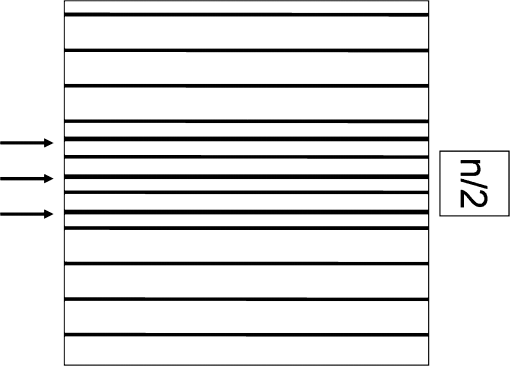
A simple method used to reduce scan time without decreasing spatial resolution is to use a rectangular FOV. This strategy is used because the axial profile of the abdomen often is rectangular. A rectangular FOV is represented by fewer lines (phase-encoding steps) in k-space spread farther apart. If the FOV is too small and tissue extends beyond the rectangle in the phase-encoding direction this will result in spatial aliasing or wrap around artifact (Figure 1). This limits the degree to which one can reduce the number of phase-encoding steps. If there was a way to unwrap the image then the scan time could be reduced further without loss of spatial resolution.
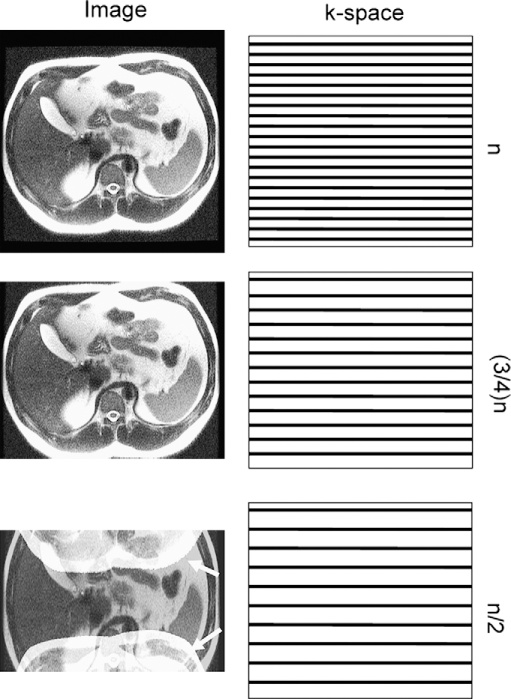
How a rectangular FOV can be used to decrease acquisition time during an abdominal scan. Left, image resulting from progressive reduction of the number of lines acquired in k-space in the phase-encoding direction (shown in right column). When only half of the lines are acquired in k-space (bottom image), the tissue extends beyond the rectangular FOV, resulting in spatial aliasing (wrap around artifact). The portion of the body outside the FOV appears on the image wrapped to the other side of the image (white arrows).
Multichannel torso phased-array surface coils with 4 to 16 coils currently are available and coils with up to 32 simultaneous receiver elements may be available in the near future. The signal intensity of tissue varies depending on its distance from any given coil. If one knows the signal intensity profile from each coil individually then it is possible to use this spatial information to unwrap an image obtained with a restricted rectangular FOV. This is the fundamental concept underlying PPI [1–8]. Strategies for acquiring the coil signal intensity profile can be divided into those in which the calibration scan is performed as a separate series (SENSE) or by more fully sampling a limited portion of k-space during the acquisition (mSENSE). Reconstruction algorithms can be divided into those in which the unwrapping is performed in the spatial domain (SENSE, mSENSE) (Figure 2) or performed in k-space (ie, GRAPPA) (Figure 3) [5,6] or both (SPACE RIP) [2].
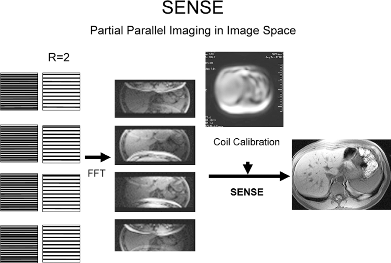
The spatial domain reconstruction algorithm (SENSE). In this example a 4-channel parallel imaging system is shown with an R of 2. For each of the 4 different receive coil elements, PPI first reduces lines acquired in k-space by a factor of 2 (R = 2) (left side), then proceeds to fast Fourier transform (FFT), generating an image for each element. Wrap around artifact is present in each image because of the undersampling in the phase-encoding direction. By using the added information provided by the signal intensity profile of each coil separately acquired through a calibration scan, the SENSE reconstruction algorithm is applied and the final image is unwrapped.
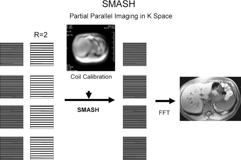
The k-space domain reconstruction algorithm (simultaneous acquisition of spatial harmonics [SMASH]). From left to right, partial filling of k space lines is seen (R = 2) for each individual coil element, then using the signal intensity profile of each coil element, the missing k-space lines are reconstructed using the SMASH algorithm before fast Fourier transform (FFT) is applied to generate an image. Again, the final image is free of aliasing artifact.
The ratio of the number of lines acquired in the phase-encoding direction necessary to completely fill k-space and generate a proper image to the number of lines actually acquired in k-space in the phase-encoding direction is called the reduction factor (R). Because the acquisition time is proportional to the number of phase-encoding lines in a Cartesian acquisition, the reduction in time is equal to the R factor. Thus, a scan with an R of 2 could be performed 50% faster than a normal scan. The theoretical limit of R is equal to the number of coil elements, however, even if 12- to 16-channel torso phased-array coils are commercially available, typically reduction factors range from 2 to 6 with current coil architectures because of other limitations related to the signal-to-noise ratio (SNR), artifacts, and geometry factor.
The advantages of PPI go beyond reduced scan time. Higher spatial resolution can be achieved for a given scan time. Reduction in image blurring and a specific absorption rate from shorter echo trains, especially in single-shot pulse sequences (ie, single-shot fast-spin echo, half-Fourier acquisition single-shot turbo spin echo) offers better image quality and safety [2,9,10]. A decrease in magnetic susceptibility artifacts from shorter echo times with echo planar imaging also has been described [9].
Calibration Scan-Related Artifacts
Because the calibration scan data are used to reconstruct the final image, it must accurately reflect the coil signal intensity profiles at the time of final image aquisition. The calibration scan data can be acquired as a separate series and then used to reconstruct subsequent acquisitions (ie, SENSE) or be incorporated into each series by oversampling of central k-space (ie, mSENSE).
When the calibration scan is acquired separately, it must be prescribed to include the entire body region to be imaged. Any area not included cannot be reconstructed, and this produces a void on the image. This artifact can be remedied by a generous calibration scan prescription (Figure 4). If a calibration scan is not performed in the same respiratory phase as the final acquisition, respiratory misregistration can lead to artifacts. At areas of strong tissue contrast differences, for example, at the diaphragmatic interface, one may see an ice-cube tray (Figure 5) artifact. Matching the phase of respiration for the calibration scan and final aquisition can help reduce this artifact, which is seen on early implementations of the ASSET algorithm. This artifact has been remedied and is no longer seen on more recent versions of the ASSET algorithm. Misregistration at the interface between the high signal of subcutaneous fat immediately beneath the surface coil and surrounding air can produce ghost reconstruction artifacts propagated through the image (Figure 6) [11]. In addition to matching the phase of respiration between calibration and final aquisition, reducing near field flare of fat signal by using fat suppression or a standoff pad between the surface coil and the skin can help reduce artifact. Many manufacturers have included pads in their surface coil designs to separate the coils from the abdominal wall.
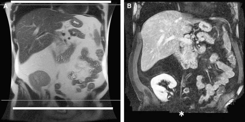
Effect of incomplete calibration scan coverage. (A) In this case, the calibration scan only covered the area between white lines. (B) When performing coronal-delayed 3-dimensional spoiled gradient echo imaging (LAVA) with SENSE (R = 2, LAVA) based on the incomplete calibration scan, the inferior portion of the prescribed FOV resulted in a void (*).
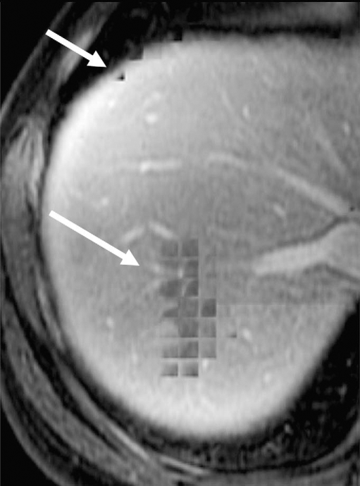
Ice-cube tray artifact. In earlier implementations an ice-cube tray–like artifact may be seen with early versions of ASSET reconstruction. This artifact has been eliminated in more recent versions. At interfaces of strong signal change such as the diaphragm against the liver, misregistration of the coil sensitivity profile can occur if the patient breathes differently between acquisitions. This can be responsible for square-like signal voids superimposing on the liver dome (white arrows) on this axial 3-dimensional postcontrast spoiled gradient echo (LAVA, R = 2; ASSET, 1.5-T, GE Excite HD), resembling an ice-cube tray.
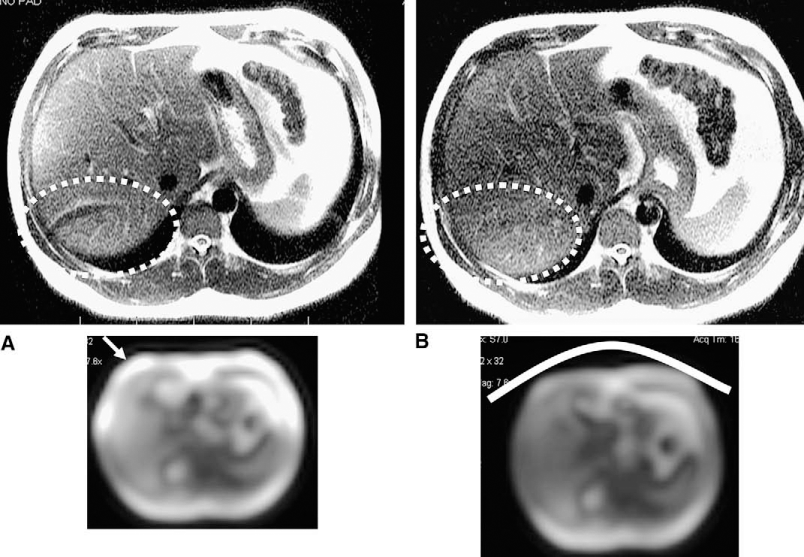
Artifact from the large signal gradient of subcutaneous fat. (A) Misregistration and undersampling during the calibration scan at the interface between the strong signal of subcutaneous fat underneath the surface coil and surrounding air on the calibration scan (arrow) can produce ghost-like artifacts through the reconstructed single-shot fast-spin echo image (dashed circle) (ASSET, R = 2). (B) The addition of a standoff pad (represented by curved white line) between the surface coil and the skin reduces near field flare of fat signal and helps reduce this ghosting artifact (dashed circle).
An alternative approach is to perform the calibration scan as part of the final aquisition by oversampling the central portion of k-space, thus avoiding misregistration and also increasing the SNR (Figure 7) [6,12–14]. Although such autocalibration techniques are of benefit, they add scan time to the final aquisition. The proportion of scan time added will increase with an increase in the R factor. Thus, autocalibration may not be optimal in applications in which speed of acquisition is especially critical and high R-factors are used such as real-time MR angiography and cardiac imaging.
Calibration data acquired at the same time as the diagnostic scan. At a reduction factor of 2 (R = 2), half the k-space lines are acquired in the phase-encoding direction, unless the calibration scan is included in the sequence, as is the case in this example. This accounts for the extra lines acquired in the center of the k-space (arrows). These extra lines contribute to the signal, and produce fewer motion-related artifacts because there is no misregistration between the calibration data and the diagnostic scan. The acquisition time is slightly longer, with the inefficiency being proportionally greater at high reduction factors (R > 2).
FOV Effects
PPI, particularly with a SENSE algorithm, can produce severe artifacts when the reconstructed FOV is less than the object size in the phase-encoding direction [8,15,16]. Uncorrected aliasing artifacts may arise from structures separated by the aliasing distance in the phase-encoding direction (ie, axial FOV smaller than patient diameter for R = 2). The artifact manifests as a speckled noise and/or a ghost of the outer portions of the FOV in the center of the image [15]. It becomes worse as the FOV is decreased further and can occur at multiple locations in the image at reduction factors greater than 2 (Figure 8). Situations in which this commonly occurs are during coronal acquisitions when the arms are left down, in obese patients, and in pelvic imaging in which small FOVs are desirable. Increasing the FOV to encompass all of the body in the area of interest will solve the problem, but at the expense of spatial resolution. Another option is to use a k-space–based PPI reconstruction method such as GRAPPA because this may produce less troublesome artifacts that interfere less with image interpretation when a small FOV is required [2,8,16]. This is explained by the fact that because image-based methods such as SENSE reconstruct each pixel by inverting a small matrix that effectively unfolds the aliased image, the additional foldover produced when using a small FOV cannot be dealt with effectively because there is currently no appropriate way to define the coil sensitivity map for multiply aliased pixels. K-space–based methods such as GRAPPA recover the missing k-space information using the neighbouring k-space points and the relationship between k-space data is not inherently altered by choosing a smaller FOV. Newer SENSE-based methods also are being implemented that are better able to deal with small FOVs through acquisition of coil maps with resolution equal to or better than the reconstructed image, modification of the basic reconstruction equations to account for the extra-aliasing by increasing the acceleration factor in the reconstruction, and development of coil sensitivity maps that take into account that extra-aliasing [8].
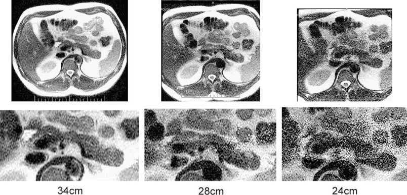
Effect of reducing FOV with SENSE-based reconstruction. Three examples of PPI with single-shot fast-spin echo sequences (ASSET, R = 2), with progressively smaller FOVs are shown. On the left image, the FOV (34 cm) is larger than the abdomen in the phase-encoding direction (anteroposterior). On the central image, the FOV is smaller (28 cm) than the object to image, which is responsible for the speckled noise observed in the center of the image. On the image to the far right, when further decreasing the FOV (24 cm) the artifact is increased.
Geometry Factor and Noise
The maximum theoretical R equals the number of elements in the phased-array coil. The maximum R factor that can be practically applied is limited by a corresponding decrease in SNR proportional to the square root of R (Figure 9). The reduction in SNR is compensated by the use of parallel imaging and additional receiver coils. There is additional SNR gain if 3-T systems are used. Thus, the simultaneous acquisition of signal from multiple receiver coils (parallel imaging) and increase in field strength are important contributors to image quality with PPI methods. There is an additional contributor to artifact and spatially dependent noise in the image called the geometry (g) factor. It depends on receiver coil geometry and the geometry of the area of interest. It describes the capability of a specific coil arrangement to unwrap a particular aliasing (wrap) pattern. The g factor depends on the distinctness or independence of each coil element's sensitivity behavior over aliased pixels. The g factor varies along with coil properties such as positioning and decoupling, which affect sensitivity behavior, imaging plane, FOV, reduction factor, and phase-encoding direction. The g factor is worse when a tissue at a specific location has a similar signal intensity profile for several surrounding coils. This usually happens in the center of the image. So this noise is spatially variable. Artifacts can occur in areas of ambiguous separation of aliased signals. This g factor is highest at the middle point between the coils and at the points farthest from the coils [17]. Also, in regions of suboptimal coil geometries, noise may be amplified because it is not distributed evenly. The typical artifact manifests as a band-like area of pixilation and noise, which often appears as a band in the center of the image (Figure 10). This phenomenon increases with increasing R factors. The coil geometry influences are different depending on the phase-encoding direction and plane of acquisition. For example, most torso phased-array coils are designed with groups of anterior and posterior coil arrays arranged linearly in groups of 4 with 1 or more rows. If the phase is cephalocaudal, there would be little signal variation in the phase-encoding direction for different points along the craniocaudal vector. There is more variation if the phase-encode direction is anteroposterior or right to left. Fortunately, this is the case in most abdominal and pelvic applications. The development of receiver coils with an optimal shape and distribution of elements for optimal image quality can help reduce overall image noise by minimizing the g factor. Because of noise and g-factor limitations, typical R factors used in body application range from 2 to 4. For larger patients low R factors may be necessary for optimal image quality.
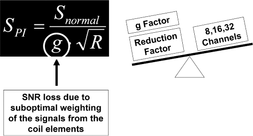
Relationship between signal, reduction factor, coil geometry, and number of receiver channels. PPI causes reduction of signal (SPI) proportional to the square root of the reduction factor (R). One might think that this signal loss could be made up for by doubling the number of receive channels, however, the signal is decreased further by the geometry factor (g), which is related to the coil arrangement and reflects its ability to unwrap a particular aliasing pattern. Thus, optimal coil performance and design are critical to good quality PPI.
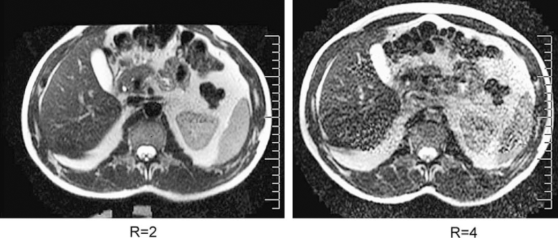
Central band of noise-like artifact from poor coil geometry (g factor) and high R factor. In this example, a 4-channel torso coil, which has not been optimized for parallel imaging, was used. As a result of the poor geometry (g) factor of this coil there is increased central band-like noise in the image as one moves from an R of 2 to 4.
With a large number of coil elements being used it is possible for a single coil to fail. This will produce an area of locally increased noise in the image and also may increase the degree of PPI reconstruction artifact in the image because of alterations in the performance and geometry of the receiver coil (Figure 11). It is important that the quality of signal from each receive coil is monitored to ensure consistent operation to maximize consistency and quality of images.

Artifact from failure of a receiver coil. Single-shot fast-spin echo image obtained using a SENSE-based algorithm (ASSET) with an R of 2. (A) Calibration scan shows low signal from the left anterolateral coil indicating coil failure. (B) The incomplete calibration data result in block-like reconstruction artifacts as well, which manifests as block-like artifacts. There is increased noise from a high g factor as well as decreased signal from the failed coil.
New Developments
Reconstruction algorithms for PPI are evolving rapidly. Although the fundamental principles of PPI remain unchanged, developments to eliminate or reduce artifacts shown in this article are being implemented with very fast timelines. FOV limitations are being overcome, severity of ghosting artifacts reduced, and SNR improved through improved robustness of reconstruction algorithms and multichannel coil designs. Parallel imaging can be interestingly added to other artifact and motion-reduction algorithms such as the recently implemented, periodically rotated, overlapping parallel lines with enhanced reconstruction (PROPELLER, BLADE) [18,19]. An increase of k-space coverage with parallel imaging in this type of sequence may further improve image quality and reduce artifacts.
Conclusions
PPI has led to significant advances in many MRI applications, and especially in body MRI, allowing a significant decrease in acquisition time, and therefore decreasing motion artifacts and increasing spatial resolution. However, it has introduced new artifacts that are related to specific parameters used in reconstruction algorithms. This article has reviewed the main artifacts seen in the early generation of SENSE-based algorithms that are specific to body applications and proposed practical solutions to minimize them. Many of theses artifacts will be minimized as improvements are made in parallel imaging parameters, reconstruction algorithms, and coil design.