
Abstract
Objectives
Recent advances in computer-modeling software allow reconstruction of facial symmetry in a virtual environment. This study evaluates the use of preoperative computer modeling and intraoperative navigation to guide reconstruction of the max-illofacial skeleton.
Methods
Three patients with traumatic maxillofacial deformities received preoperative, thin-cut axial CT scans. Three-dimensional reconstructions, virtual osteotomies, and bony reductions were performed using MIMICS planning software (Materialise, Ann Arbor, MI). The original and “repaired” virtual datasets were then imported into an intraoperative navigation system and used to guide the surgical repair.
Results
Postoperative CT scans and photographs reveal excellent correction of enophthalmos to within 1 mm in patient 1, significant improvement in symmetry of the nasoethmoid complex in patient 2, and reconstruction of the zygomaticomaxillary complex location to within 1 mm in patient 3.
Conclusion
Computer modeling and intraoperative navigation is a relatively new tool that can assist surgeons with reconstruction of the maxillofacial skeleton.
The concept of open reduction and internal fixation of facial fractures was popularized in the 1970s and 80s. This remains the standard of care for most facial fractures. However, there are situations in which an accurate reduction and restoration of facial symmetry is extremely challenging. These include complex facial fractures, fractures involving the orbit, and secondary reconstructions of the naso-orbito-ethmoid and zygomaticomaxillary complexes. Surgeons have recently started to evaluate presurgical planning with computer-aided design/modeling (CAD/CAM) software as well as intraoperative computer-aided surgical navigation systems to assist with repair of these complex injuries.1–4 The CAD/CAM software allows the surgeon to import 2-di-mensional computed tomography (CT) data and generate a precise 3-dimensional, virtual representation of the skull. The proposed surgical repair can then be performed on the virtual skull, including the osteotomies and the bony reduction. Finally, the CAD/CAM reconstructions are imported into a computer-aided surgery system and used to guide the repair. This article presents a retrospective review of 3 patients who underwent secondary reconstruction of the orbit, naso-orbitoethmoid region, and zygomaticomaxillary complex using this technique.
Methods
After obtaining institutional review board approval, a retrospective chart review was performed to evaluate the results of CAD/CAM modeling and CAS navigation systems for the repair of 3 complex maxillofacial traumas. A pre-operative thin-cut (1–1.5 mm), axial CT scan was obtained in all patients. These data were recorded in a generic DICOM (Digital Imaging and Communications in Medicine) format from the CT scanner. The data were then transferred via an Intranet connection to a Windows-based computer workstation with MIMICS CAD/CAM software (Materialise, Ann Arbor, MI). The MIMICS software converts DICOM data into a proprietary format; compiles the 2-dimensional axial images; and presents the data in axial, coronal, sagittal, and 3-dimensional reconstructions. Virtual osteotomies were then performed to segment the facial skeleton. Uninjured segments were mirrored across the mid-line to provide a template for injured segments. Once the planned reconstruction was completed, a process was developed to “back convert” from the MIMICS format to DICOM. Both the original CT dataset and the virtual reconstruction were then transferred to a Tria (Medtronic-Xomed, Jacksonville, FL) intraoperative navigation system. Stereolithographic models were also fabricated from the virtual reconstructions to be used as backup in the operating room. Once in the operating room, the intra-operative registration process was completed. The surgical probe could then be placed anywhere on or within the patient, and the monitor would project the exact location of the probe in axial, coronal, sagittal, and 3-dimensional views (Fig 1). The virtual skull projected on the monitor could also be “toggled” between the original and virtually repaired data sets.
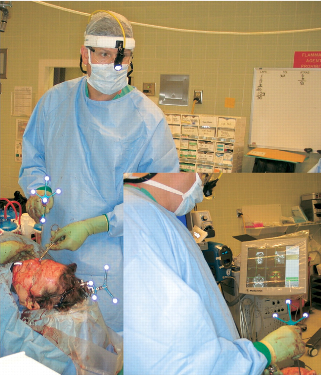
A photograph of intraoperative CAS navigation system in use. Note the surgical probe being used to define a specific anatomic landmark and the reference arc rigidly fixated to the patient's skull. The CAS navigation system projects the location of the surgical probe on a computer monitor, in axial, coronal, sagittal, and 3-dimensional views (inset).
Surgical exposure was obtained, and the proposed osteotomies were localized with the intraoperative navigation system (using the original, unaltered CT data). The osteotomies were performed with a sagittal saw and osteotome, allowing mobilization of the appropriate bone segments. The Tria navigation system was then toggled to display the virtual CT dataset (ie, the dataset that had undergone virtual surgical repair), and the preplanned, final reduction was depicted on the monitor as a template for the surgeon. A gross reduction was performed using visual cues from the patient's anatomy. The intraoperative navigation probe was then placed on multiple different areas of the mobilized bone segment to precisely confirm or modify the reduction. Once the actual reduction accurately approximated the preplanned virtual repair, internal fixation was applied. Finally, the incisions were closed, and a postreduction CT scan was obtained.
Patient 1
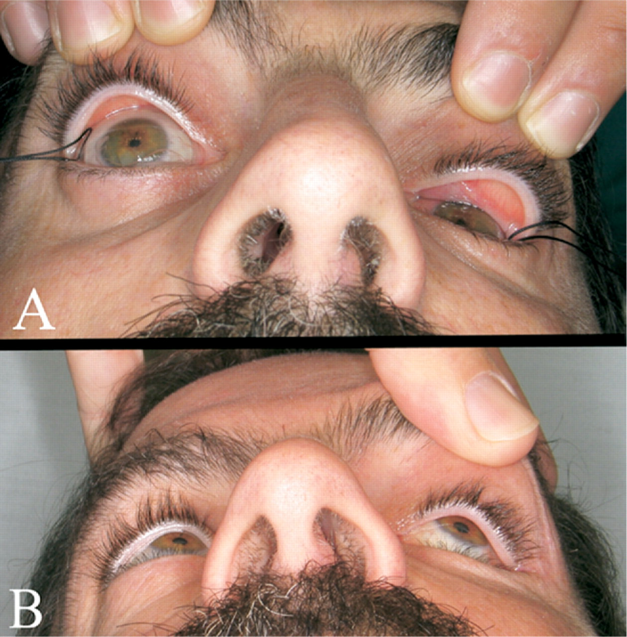
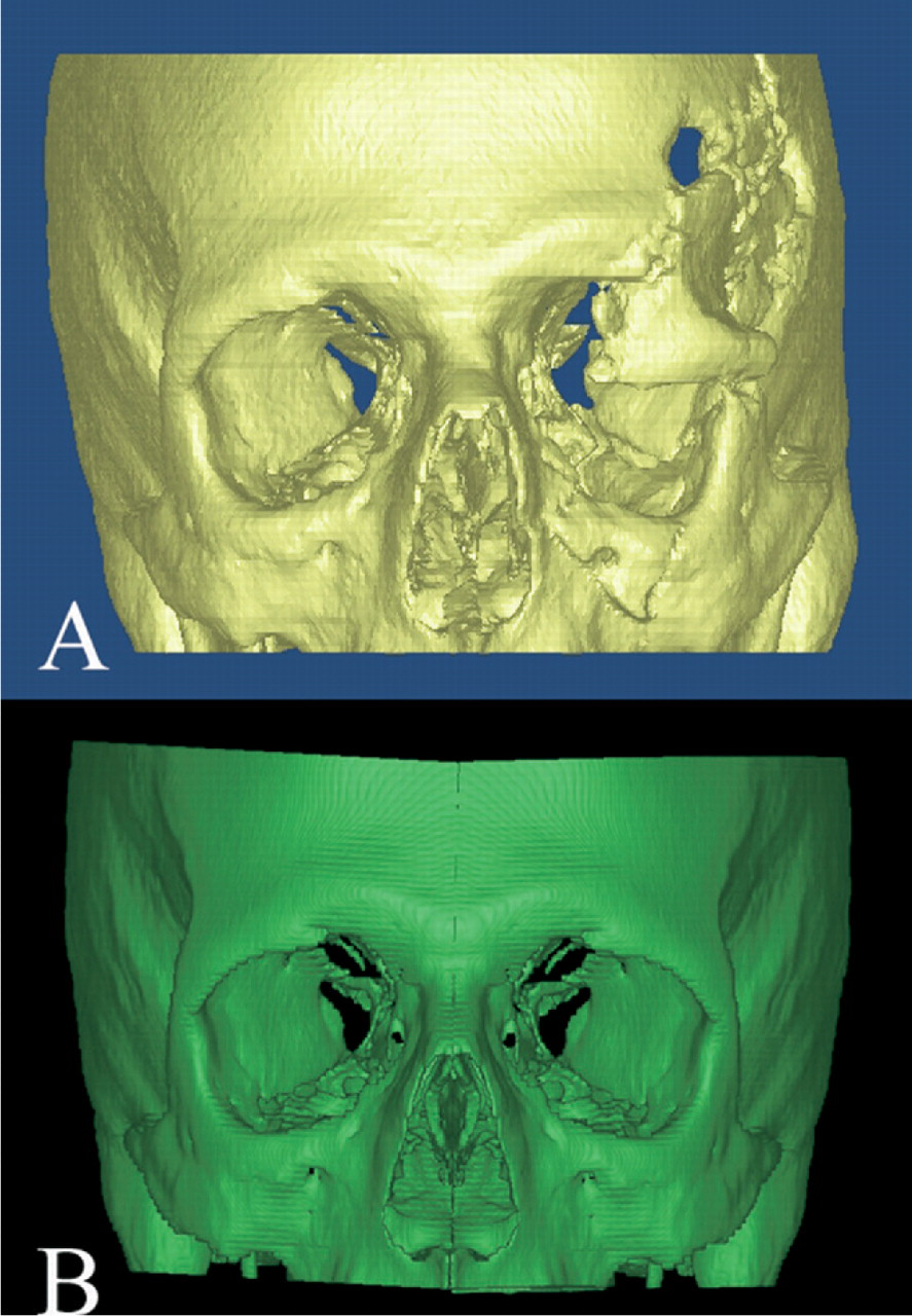
The patient was a 47-year-old man who was involved in a motor vehicle accident and sustained a severely displaced, left sided, fronto-orbitozygomatic fracture. He presented 6 weeks after an attempted surgical repair. Pertinent physical findings included marked displacement of the fronto-orbital bar (allowing only limited access to the globe); severe malar depression; enophthalmos; hypophthalmos; and extraocular muscle limitation in superior, medial, and downward gaze (Fig 2A). In addition, he sustained a traumatic ptosis and left optic nerve injury (light perception only). A preoperative CT scan revealed a severely displaced superior orbital rim, lateral orbital wall, and orbital floor. There was increased orbital volume with bony diastases of the orbital floor and roof as well as depression of the zygomaticomax-illary complex (Fig 3A).
(
(
Preoperative CAD/CAM modeling was used to mirror the uninjured right zygomaticomaxillary complex and orbit onto the left side (Fig 3B). The virtual repair was then back converted into DICOM format and imported into a Tria intraoperative navigation system. Combined coronal, transconjuctival, and sublabial incisions were used. The previously placed hardware was removed. Osteotomies were performed to mobilize the frontal bar and zygomati-comaxillary complex. Resorbable mesh was molded (in 3 dimensions) onto the stereolithographic model and applied to the stable edges of the skull. The initial reduction was guided by the resorbable mesh. Final modifications of the reduction were guided by the intraoperative navigation system. Because the resorbable mesh was quite thick, smaller titanium plates were applied to maintain the final reduction, and the resorbable plates were cut off with an ophthalmic cautery. A porous polyethylene sheet was then fashioned for orbital floor reconstruction. The exact placement was determined by the intraoperative navigation.
Patient 2
The patient was an 11-year old girl involved in a motor vehicle accident, resulting in a complex open skull fracture with traumatic brain injury as well as a severe naso-orbito-ethmoid fracture. Her prognosis was very poor, and her hospital course was complicated by meningitis and elevated intracranial pressures. The neurosurgeons performed crani-ectomies involving both the right frontal and left parietal bones. Because of her grave prognosis, the neurosurgeons recommended a delayed repair of her facial fractures until her medical condition improved. She subsequently presented 6 months after the initial injury for definitive repair of her facial fractures.
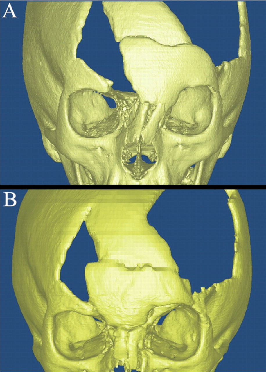
Physical examination revealed bony defects in the right frontoparietal and left parietal regions. There was marked leftward deviation of the nasal dorsum with telecanthus (Fig 4A). The intercanthal distance was 30 mm; the interpalpe-bral fissure widths were right 27 mm and left 26 mm. A CT scan revealed a complex naso-orbito-ethmoid fracture, left frontal bone displacement with overlap at the superior edge, left-sided parietal skull defect, and a right-sided anterior frontal bone defect extending into the skull base (Fig 5A). An encephalocele was noted extending into the anterior ethm.oid sinuses
(
(
The virtual osteotomies were created, and a virtual repair was performed (Fig 6). The virtual repair was then back converted into DICOM format and imported into the intra-operative navigation system. By using a coronal incision, the frontal and naso-orbito-ethmoid areas were exposed. A sagittal saw and osteotomes were used to perform the osteotomies. Once the frontal bone and naso-orbito-ethmoid complex were mobilized, transnasal sutures were passed to reconstruct the left medial canthus. The nasal bones were also reduced. Initially, resorbable mesh was molded onto a prefabricated stereolithographic model and used to grossly localize the free-floating frontal bone segment. Unfortunately, this was found to be of little use. The reduction was then guided by using the CAS navigation system. The right anterior frontal and left parietal skull defects were reconstructed with alloplastic implants during a second procedure.
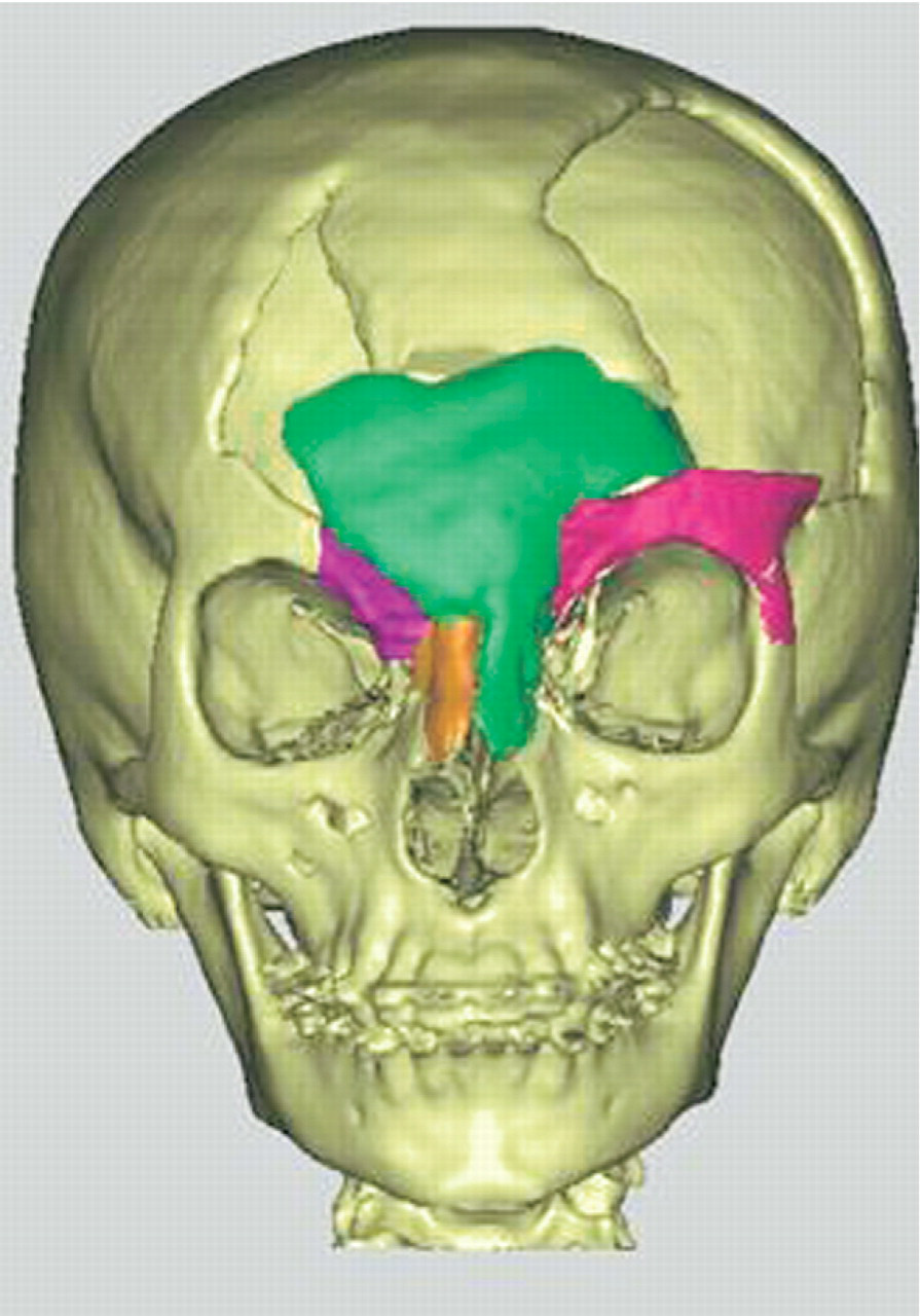
Virtual representation of the planned repair in patient 2. The frontal and nasal bones as well as the left superior orbital rim were medialized to obtain skeletal symmetry.
Patient 3
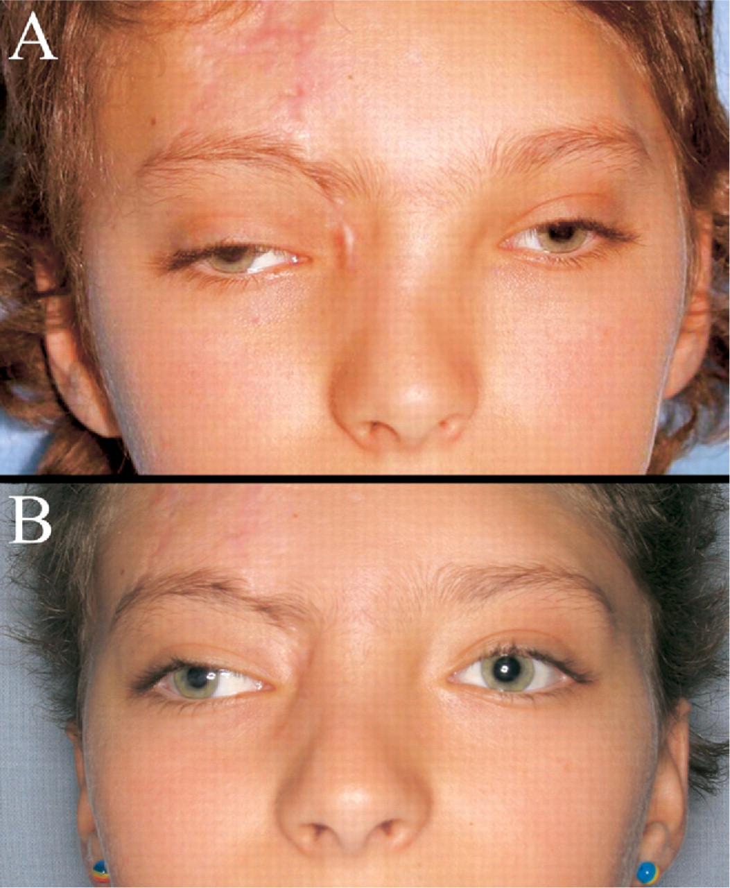
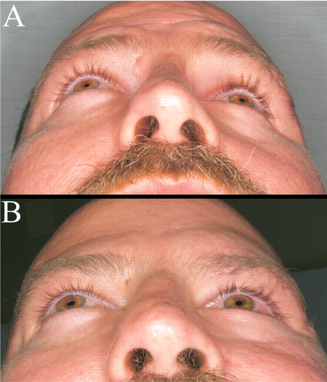
The patient was a 36-year-old man who sustained a complex left orbitozygomatic fracture in a motor vehicle accident. He presented to our institution 6 months after repair of a leftsided ruptured globe and attempted repair of his facial fractures. He had persistent complaints of facial asymmetry, globe malposition, and diplopia. On physical examination, he had marked malar flattening, left-sided enophthalmos, hypophthalmos, and malposition of the lateral canthus (Fig 7A). He had diplopia in all cardinal directions of gaze. A preoperative CT scan revealed malpositioning of a titanium orbital floor implant, marked malar depression with posterior displacement of the orbital rim, and lateralization of the zygomatic arch.
(
A preoperative CAD/CAM virtual reconstruction was performed using the MIMICS software. The patient's right orbitozygomatic complex was mirrored to the left and used to replace the damaged left orbitozygomatic complex. The virtual repair was then back converted into DICOM format and imported into the intraoperative navigation system. Combined coronal, transconjuctival, and sublabial approaches were used. The previously placed hardware was removed. The preplanned osteotomies were performed at the medial orbital rim, zygomaticomaxillary buttress, root of the zygomatic arch, and zygomaticofrontal suture line.
Once the zygomaticomaxillary complex was released, the mobilized bone segment was advanced anteriorly approximately 1.5 cm and medialized approximately 1.0 cm (Fig 8) using the navigation system to define the exact location of the free-floating segment. Once the reduction accurately approximated the virtually repaired CT scan, 1.3 titanium miniplates were applied. The orbital floor was reconstructed using prebent titanium mesh molded onto a stereolitho-graphic model. The CAS system was used to assure accurate placement of the orbital implant. The incisions were closed and a postoperative CT scan was obtained. It revealed excellent bony reduction and good posterior positioning of the floor implant. Unfortunately, the anterior-lateral edge of the orbital floor implant became bent during insertion. This required re-exploration of the orbit and replacement of the implant.
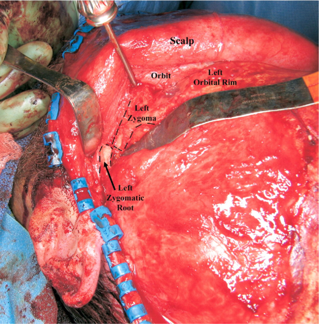
An intraoperative photograph of patient 3 depicting the mobilized left zygomaticomaxillary complex as it is advanced and medialized. The dashed lines denote the final position of the bony segments. There is a 1.5-cm step-off between the left zygo-matic root and the reduced zygomatic arch (ultimately, osteotomies were performed to medialize the zygomatic root).
Results
Patient 1
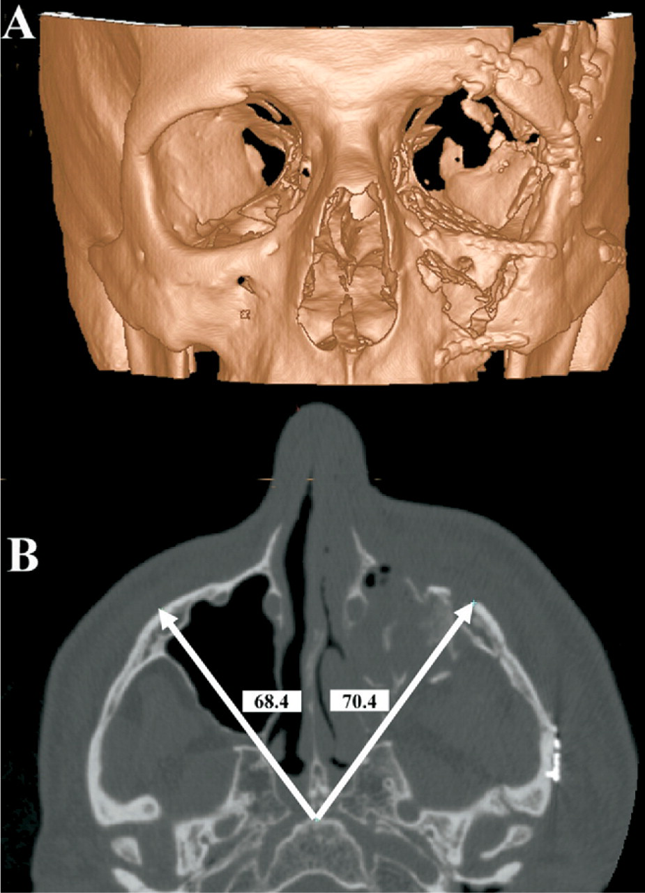
A postoperative CT scan revealed improved orbital symmetry (Fig 9A) and reduction of the malar eminence to within 2 mm (Fig 9B). The orbital floor implant is radiolucent (porous polyethylene) and does not appear on the image. Clinical examination revealed no enophthalmos and slight hyperglobus (Fig 2B). The patient was highly satisfied with the bony repair but had failed to follow up with a ptosis repair at the time of the photograph.
(
Patient 2
A postoperative CT scan revealed closure of the right cranial defect/encephalocele as well as improved symmetry of the naso-orbitoethmoid complex (Fig 5B). Postoperative photographs reveal a significant reduction in the telecanthus and improved symmetry of the nasal root (Fig 4B).
Patient 3
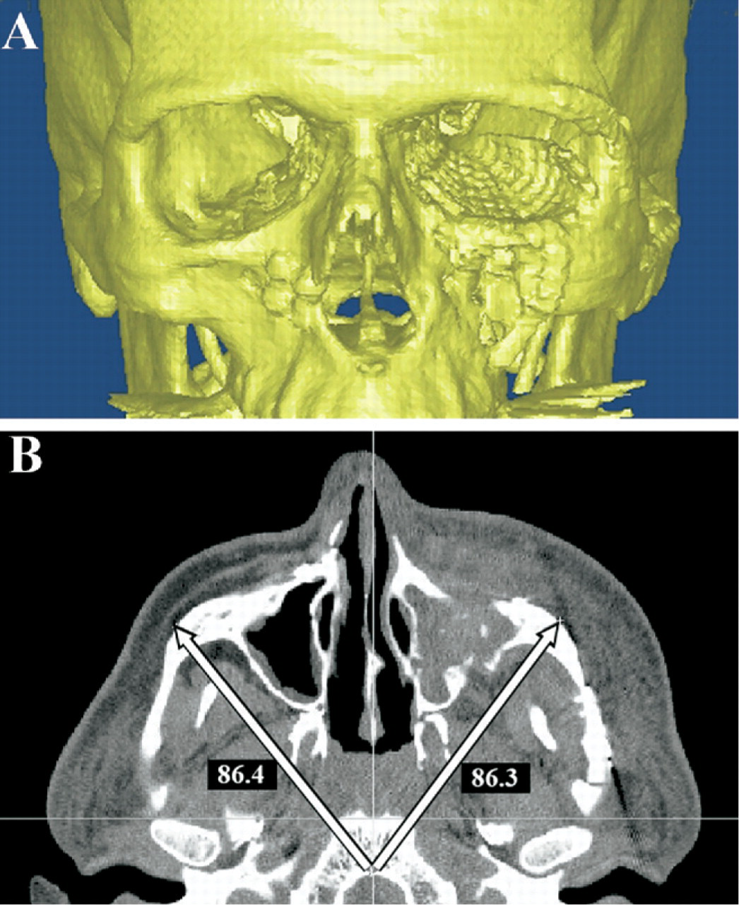
Postoperative CT scans reveal excellent symmetry of the inferior orbital rim and floor implant (Fig 10A). The malar eminence was reduced to within 1 mm of the contralateral side (Fig 10B). Postoperative photographs reveal good globe position with minimal residual enoph-thalmos (Fig 7B).
(
Discussion
Secondary reconstruction of maxillofacial injuries is extremely challenging. Bone remodeling causes distortion of normal anatomic landmarks, and the surgical exposure does not offer the surgeon an unobstructed view of the entire facial skeleton. Surgeons have relied on experience and a “mind's-eye view” to reconstruct the skeletal symmetry. The introduction of computer-aided surgical navigation systems and CAD/CAM software offers additional tools to assist the surgeon with reconstruction of facial symmetry.
Computer-Aided Surgical Navigation
Intraoperative navigation systems were initially developed for neurosurgical applications; they are now commonly used for endoscopic sinus surgery as well. These navigation systems allow the surgeon to determine the precise location of any instrument or bony anatomic landmark to within approximately 1 to 2 mm. 5 The most common computer-aided surgery systems currently available include Instatrak (General Electric Health Care, Buckinghamshire, UK), Stealth Station (Medtronic-Xomed, Jacksonville, FL), Stryker Navigation System (Stryker-Leibinger, Kalamazoo, MI), and VectorVision (BrainLab, Westchester, IL). Each system has advantages and disadvantages.
The InstaTrak system uses an electromagnetic platform to localize the patient in space. A radiofrequency sensor is mounted into a specialized headset worn by the patient. A second sensor is incorporated into the surgical probe. Movement of the sensors alters the local magnetic field. These changes in the magnetic field allow the navigation system to precisely localize the patient and probe in space. The major advantage of electromagnetic systems is a rapid intraoper-ative patient-registration process. Unfortunately, metallic objects such as surgical instruments and the operating table can disrupt the electromagnetic field and result in inaccuracies.
The StealthStation, Stryker, and VectorVision systems use an optical platform to localize the patient in space. Optical systems use infrared-emitting diodes or reflectors to track the patient and surgical probe in space. Optical systems are quite versatile, and their accuracy is not disrupted by ferrous materials. The primary disadvantage is the need to maintain a direct line of site between the infrared-emitting diodes on the patient/instrumentation and the infrared sensor.
Attempts were made to use surgical navigation systems in maxillofacial reconstruction soon after their mainstream introduction. 6 Unfortunately, they were of limited utility because the DICOM datasets projected for the surgeon remained unaltered. If the patient was positioned in the CT scanner with the head at an angle, any attempt at comparing symmetry across the midline was extremely difficult. Even when the patient was scanned in a true orthogonal position, the best a surgeon could hope for was determining single points of the reduction and then looking at the contralateral side on the monitor to determine if the reduction was symmetric.
CAD/CAM Software
The introduction of CAD/CAM software provides the surgeon an opportunity to perform virtual manipulations of the CT datasets preoperatively. This includes repositioning of the patient into true orthogonal planes, segmentation, and mirroring of the facial skeleton as well as virtual osteotomies and bony reductions. CAD/CAM software programs have some utility in isolation (ie, presurgical planning, teaching, illustrations, and so on) but have limited clinical application until some type of interactive tool is applied for use in the operating room. Initially, this interactive tool was a stereolithographic model. 7, 8 An exact replica of the repaired facial skeleton could be fabricated, sterilized, taken into the operating room, and used as a template for the actual repair. Although stereolithographic models are efficacious, they are only a guide. They do not confirm the “real-time” bony reduction. Intraoperative navigation provides this “real-time” update. An accurate representation of the planned surgical result is projected for the surgeon. He/she can then repeatedly assess the bony reduction in 3 planes to assure that the repair is consistent with the planned outcome. The navigation can also be used to assist with the placement of implants (eg, orbital floor reconstruction). Depending on the anatomic location and complexity of the repair, a stereolithographic model may or may not be used. In the authors' experience, more complex secondary reconstructions such as the internal orbit still require both a stereolithographic model and CAS to guide the repair.
There are several CAD/CAM programs currently available for use in maxillofacial surgery. These include Amira (Berlin, Germany), Analyze (AnalyzeDirect, Lenexa), iPlan (BrainLab, Westchester, IL), MIMICS (Materialise, Ann Arbor, MI), and Voxim (IVS Solutions, Chemnitz, Germany). The authors currently use MIMICS as their primary software for maxillofacial reconstruction but have had experience with iPlan and Voxim. Future discussions will be limited to these three programs. All 3 software applications offer the ability to import DICOM data and perform virtual manipulations. 3 The DICOM format was developed in 1993 as a “gold standard” for digital images generated by radio-logic hardware, and it allows communication among physicians and equipment. 9 All current CT scanners, surgical navigation systems, and CAD/CAM software with medical applications import DICOM data. Unfortunately, after the presurgical manipulations are complete, the iPlan and Voxim programs offer no capability for back conversion from their proprietary language to the standard DICOM format. Therefore, data transmission between surgeons and institutions that do not have the same software/hardware is not possible. The authors have collaborated with software engineers at Materialise to develop a technique for back conversion of the MIMICS software to DICOM format. This allows surgeons to perform complex virtual reconstructions with MIMICS software and then back convert the data to DICOM for use in any surgical navigation device.
The utility of computer-aided maxillofacial surgery is most clearly shown when compared with traditional reduction methods. Surgeons generally use multiple incisions for an acute fracture repair. Because visualization of the entire injury is not possible, the surgeon must move between incisions and visualize several different fracture sites to determine the final reduction. Much like a jigsaw puzzle, step-offs and small irregularities at the fracture margins are used as visual cues.
Although the success rates in acute fracture repair are very good, secondary reconstruction of the same injury is significantly more complex. The jigsaw fracture patterns and step-offs are effaced by bone remodeling. This gives the impression that fractured bone segments are much closer to their premorbid position than they actually are. Therefore, surgeons tend to underreduce the bone segments. Even surgeons who understand this phenomenon are challenged by secondary reconstructions because it is extremely difficult to accurately visualize the entire reduction while only looking through incisions at the periphery of the mobilized bone segment.
CAD/CAM and surgical navigation systems can be used to augment the surgeon's perspective on the repair. In the case of patient 1, the fronto-orbital bar was severely displaced, covering the anterior aspect of the globe. The malar eminence was depressed, and the internal orbital fractures had not been repaired. Virtually all the normal bony landmarks had undergone significant remodeling (Fig 3A). In-traoperative navigation allowed accurate repositioning of the zygomaticomaxillary complex to within approximately 2 mm of the contralateral side (Fig 9B). The fronto-orbital bar was reduced, and the internal orbit was reconstructed, 1 resulting in good globe positioning (noenophthalmos and mm of hyperglobus) (Fig 2B). In the case of patient 2, precise positioning of the frontal bone was difficult because the normal bony landmarks had been removed or remodeled (-Fig 5A). Intraoperative navigation allowed accurate positioning of the mobilized bone segments (Fig 5B), resulting in improved facial symmetry (Fig 4B). Patient 3 had maarked depression of the left zygomaticomaxillary complex with globe malposition and malar flattening (Fig 7A). An accurate reduction required posteromedial mobilization of the zygomaticomaxillary complex(Fig 10A). However, the precise positioning was difficult to determine. Feedback from the intraoperative navigation system allowed accurate positioning of the zygomaticomaxillary complex despite the fact that the fracture margins did not line up. The reduction resulted in a 1-cm bony step-off at the orbital rim and 1,.5-cm step off at the root of the zygoma (Fig 8). Small intermediate osteotomies were performed to bridge the defects and provide bony continuity of the zygomatic arch. The end result was a precise reduction of the malar emineence to within 1 mm of the uninjured side (Fig 10B). The CAS navigation system was used to assist with implant placement along the orbital floor and lateral orbital wall. Postreduction CT revealed excellent symmetry. Final globe position revealed 1 mm of enophthalmos and good globe height. The authors believe that the use of CAD/CAM presurgical planning and intraoperative navigation significantly improved the accuracy of each repair.
Conclusion
Computer-aided “virtual surgery” and intraoperative navigation are viable techniques in maxillofacial reconstruction. They augment the surgeon's 3-dimensional perspective of the repair and appear to provide improvement in the accuracy of bony reductions.
Author Information
Author Contributions
Financial Disclosure
None.