
Abstract
Hot isostatic pressing (HIP) units are worldwide used for the compaction of metal alloy powders. The cooling rate in a HIP unit is usually comparatively low. This lengthens cycle times and requires an additionally heat treatment for quenched and tempered steels. Novel cooling HIP concepts in HIP units feature high quenching rates. In this study, tool steels were investigated with respect to their time–temperature–transformation behaviour for different cooling parameters. The paper shows that encapsuled powdered tool steels can be compacted and hardened in the HIP unit. The examined steels exhibit a comparable or even a higher hardness and a finer microstructure. HIP units with high-quenching rates enable to compact and heat treat materials in one step.
Keywords
Introduction
Hot isostatic pressing (HIP) is used to process metallic powders to semi-finished products and near-net-shaped parts with isotropic properties and without porosity. After this heat treatment, cooling occurs by radiation and natural convection of the compressed gas, which can take up to several hours depending on the furnace and workpiece dimensions. For most technically used metals, this slow cooling leads to a softening and necessitates further heat treatments after HIP. In addition, slow cooling takes up about half of the cycle time, thus faster cooling could cut the cycle time in half. Developers of HIP devices have come up with different approaches to increase the cooling rates in HIP units.
One approach to accelerating the cooling rate is to increase free convection, which is caused by differences in density resulting from temperature differences. 1 This process can be boosted by a fan or a blower inside the pressure vessel, which increases the flow rate of the gas and thus heat transfer. Cooling rates of about 30–40 K min−1 are achievable.
Another approach is to install a heat exchanger in combination with a pump. The pump feeds the hot gas out of the vessel, through the heat exchanger, and back into the vessel when it is cold. The company Avure has commercialised this principle since the 1980s under the name ‘Uniform Rapid Cooling’.2–4 The resulting cooling rates are claimed to be of 40–100 K min−1, depending on the type of press. With the faster cooling inside the HIP, it is possible not only to reduce costs by shortening the cycle time, but also to integrate part of the heat treatment of the material into the HIP cycle. Some materials can be cooled directly after solution annealing, so that this heat treatment step can be economised. The company Bodycote has published a paper in which they describe a method of compacting an aluminium alloy, followed by integrated solution annealing and fast cooling in the HIP cycle. It was shown that the mechanical properties were on the same level as those of specimens that had been compacted and solution-annealed in two separated steps.5,6
A current approach that provides even faster cooling rates is the so called ‘Ultra (Uniform) Rapid Quenching’ (URQ), which is also based on internal gas cooling by convection. A heat sink to cool the gas is installed inside the pressure vessel, and thus the gas does not exit the vessel, which greatly accelerates the cooling rate. It is claimed to be up to 3000 K min−1.7–9
These cooling rates are, in principle, more than sufficient to directly harden steels. Annealing processes can also be included in the cycle so that no subsequent heat treatment would be necessary. This technique makes it possible to densify and heat-treat powder metallurgical steels in one step, which is a huge economical benefit. Numerical calculations made by the press manufacturer indicate a very uniform cooling behaviour of the workpieces, which should lead to a good dimensional accuracy, despite the high cooling rates.10,3
Hardening of steels in highly pressurised gases represents a completely new form of heat treatment. Furthermore, there is little thermodynamic data available for the technical gases used, e.g. argon and nitrogen, in these high temperature and pressure ranges. This necessitates theoretical considerations of the influences of the cooling agent on cooling behaviour and cooling rate of a body.
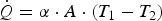
The heat flow
 can basically be written as
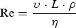
The Reynolds number (Re) is defined as
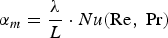
In the simplified consideration in which the specimen is a constant source of heat, the Prandtl number is defined as

These equations show that there are several factors that influence the heat-transfer coefficient and which depend on the properties of the fluid, the geometry of the body, and also the flow rate. Furthermore, the properties of the fluid depend on the applied temperature and pressure.
To gain information about the influences on cooling, this study aimed to keep many constraints constant. The test body was chosen to be an austenitic rod, which provides a comparable geometry, thermal conductivity, and density of the test body for all tests. The temperature from which the cooling started was chosen to be 1300 °C and the cooling water was constantly at 30 °C. This provides a similar temperature difference at the beginning of each test. With these constraints, influences on the cooling rate of the specimen were examined.
To harden steel, fast quenching is vital in order to form martensite and to avoid the softer phases such as ferrite, pearlite, and bainite, which form at slower cooling rates. Alloying elements such as chromium and nickel inhibit the formation of the softer phases, thus critical cooling times differ for each alloying system. The time required to quench from 800 to 500 °C is commonly used as an indication for the avoidance of pearlite formation. This interval is defined as t8/5. The time tC8/5 is the critical cooling time between 800 and 500 °C that is just sufficient to avoid pearlite formation. Steels that are alloyed to an extent such that the cooling time is not critical for avoiding of pearlite or bainite, often tend to precipitate carbides during cooling. 12 These so-called pre-eutectic carbides precipitate in the temperature region between 1000 and 700 °C, hence the critical time during cooling to prevent pre-eutectic carbides is tC10/7. 13 These cooling times, which are particularly important for materials scientists, have not yet been measured in the fast-quenching HIP and will be analysed in this study.
But it is important not only to analyse the cooling times, the effect of high pressure on the microstructure of high-alloyed steel also requires further investigation.
There is a known effect of pressure on the equilibrium temperature of pure iron.
14
The α/γ equilibrium temperature decreases on increasing the pressure, whereas the melting temperature increases on increasing the pressure. This effect is generally described by the Clausius–Clapeyron equation:
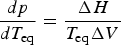
Several studies show that an increase in temperature leads to a decrease in martensite start temperature. The molar volume of austenite is smaller than the molar volume of ferrite or martensite. This can be illustrated by a simplified G(T) curve of the austenite and martensite phases (see Fig. 1).15–17
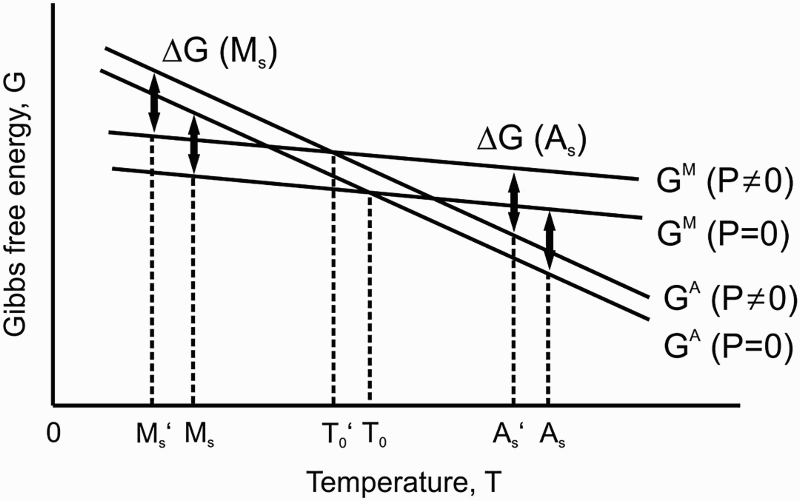
According to the Clausius–Clapeyron equation the free enthalpies of both phases increase with increasing pressure. Thus the G(T) lines are shifted upwards and, as a consequence, the intersection of both lines is shifted to lower temperatures and also the martensite start temperature MS and austenite start temperature AS. The pressure-related shift in MS temperature for steels has been calculated18,19 or measured16,20 by several researchers. Their results indicate that the shift in martensite start temperature due to the applied pressure lies between 15 18 and 4.8 °C 16 per applied 100 MPa.
Not only the thermodynamic equilibrium is changed by the pressure, the precipitation kinetics from the austenite are also influenced by high pressures. Several studies deal with this subject.16,21–25 Pure Fe–C alloys have been examined as well as commercially available low-alloyed steels. Isothermal time-temperature-transformation (TTT) diagrams have been investigated at different pressures and compared to TTT diagrams that were measured under atmospheric pressure. The studies were performed in diamond-die-cells with hydrostatic pressures in the GPa range. All studies have in common that a high pressure shifts the transformation noses to lower temperatures and to longer periods of time. Thus the pressure has a similar effect as alloying elements. Figure 2 shows the influence of 2.4 GPa on a plain carbon steel with 0.44 mass% C. The effects are explained, on the one hand, by a shift of the transformation temperature in the equilibrium state
25
and, on the other hand, by retardation of nucleation by the high pressure.
21
However, the examined pressures are orders of magnitudes higher and it thus remains unresolved as to whether the effects are still noticeable when pressures that are present in a HIP are applied. A recent publication deals with this topic. The shift in the transformation lines that was measured in the GPa range was linearly interpolated to a shift in the transformation lines under HIP pressures of 200 MPa. The resulting shifts in the transformation time are 1.5,
22
2,
24
7,
21
and 40 times
23
longer. The large differences in the determined shifts show that there is still need for research in this field. However, it can be concluded that the influence on the precipitation kinetics in steels, when quenched under HIP pressure, is likely to be present, but has not been investigated intensely. The first publication about the application of URQ with iron-based materials was in 2012. It was performed by the company Indexator in cooperation with the press manufacturer.
26
That publication reports that the mechanical properties of ausferritic ductile iron (ADI) are drastically improved by the combination of HIP and heat treatment. The process is patented under the name AusFerHIP.
27
In this process, ADI with increased silicon content is austenitised in the HIP. The high pressure closes casting defects such as pores and shrink holes. Subsequently, the part is quenched until just before the martensite start temperature and then held there. The high pressure, the high temperature and the high silicon content are reported to provide a fine acicular ferrite by delaying the formation of Fe3C carbides and bainite.8,26 In addition to iron-based materials, the impact of high pressure during heat treatment has been studied with titanium alloys. The influence on the phase content in Ti–46Al–8Nb (at.-%) was studied in.
28
The material was quenched from 1360 to 850 °C in a salt bath, which resulted in a one-phase γ-Ti microstructure. These specimens were subsequently kept at 1280 °C either in a vacuum furnace or in a HIP at a pressure of 150 MPa. The specimen treated in the vacuum furnace showed distinct precipitations of α-Ti, whereas the volume content of α-Ti in the specimens treated in the HIP was much lower. In a second step, the HIP specimen was annealed in the vacuum furnace, and the specimen that had been treated in the vacuum furnace was placed into the HIP with 150 MPa, both again at 1280°C. It was shown that the effect of the pressure on the microstructure was reversible. In the vacuum furnace, precipitates of α-Ti grew, whereas the content of α-Ti was reduced in the HIP. This effect was explained by differences in the atomic volumes of the two titanium phases. γ-Ti possesses a lower atomic volume and is thus explained to be stabilised under high pressure. Similar results were obtained with the titanium alloy Ti–5Al–5Mo–5V–3Cr (mass-%) in Cao et al.
29
This alloy consists of β-Ti with small amounts of α-Ti. The authors conclude in this case as well that the dissolution of α-Ti is enhanced by application of 200 MPa during heat treatment. Additionally, a quantitative analysis of the influence of pressure on the thermodynamic equilibrium was performed utilising Clausius–Clapeyron equation. They found that at pressure of 200 MPa the equilibrium is shifted by 16 K. Thus, the volume content of α-Ti that was present after HIP treatment corresponds to a content that is reached with an increase in temperature of approximately 16 K in the vacuum furnace.
The effect of 2.4 GPa on the isothermal TTT diagram of a steel with 0.44 mass% of carbon.
23
The transformation lines have shifted to lower temperatures and longer time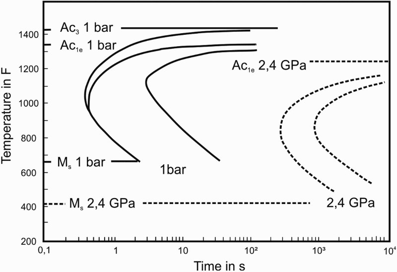
This paper aims to describe quenching of steel specimens using the URQ system in a HIP from the material science point of view and to compare cooling in a HIP with other mechanisms. Therefore, this paper is divided into two parts. First, cooling in the HIP is characterised by test cycles using specimens with drill holes for temperature measurements. These are used to derive the cooling rates. These specimens are made of austenitic steel to prevent an influence of latent heat. A test specimen is used for direct comparison of cooling in the HIP and in a vacuum furnace.
To estimate the effect of HIP-quenching on martensitic hardenable steel, different martensitic steels were austenitised and quenched in the HIP as well as in oil or in a dilatometer with gas cooling. The resulting hardness and microstructure was evaluated.
Experimental
Specimen preparation
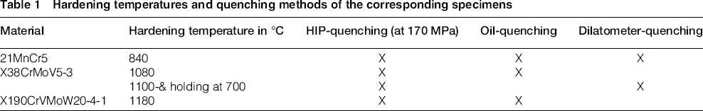
Hardening temperatures and quenching methods of the corresponding specimens
HIP
The rods for cooling trials were placed vertically into the middle of the furnace bottom plate. Thermocouples (Type B) were placed into the drilled holes, and into the gas next to the specimen at half-height.
For quenching of martensitic steel, the specimens were hung centrically inside the HIP furnace with the help of molybdenum wire, in order to obtain the preferably highest cooling rates. Compaction of the powder was not emphasised in this study. Every cycle consisted of the following steps: Repeated evacuation to 10−4 bar, equilibrating the pressure up to 10 MPa, increasing the pressure and temperature simultaneously up to 170 MPa and desired hardening temperature, respectively. While the temperature was increasing with 30 °C min−1, the pumping rate of the compressor could not be programmed for technical reasons. However, to ensure that the pressure and the temperature reach their desired values at the same time an isothermal holding step was inserted. The holding time at the hardening temperature was 30 minutes with a constant pressure of 170 MPa, followed by URQ to 50°C. Thereafter the pressure was released.
Quenching in oil and dilatometer
The specimens for oil-quenching were heat-treated in a conventional muffle furnace under a protective gas atmosphere. After reaching the target temperature, the specimens were placed inside the furnace. The holding time was 30 minutes followed by quenching in oil. The specimens were transferred manually.
To identically reproduce the temperature profile of the HIP cycle, specimens were also heat-treated in a dilatometer (DIL 805 A/D, Bähr-Thermoanalyse GmbH) under a vacuum. Temperature measurements were made using thermocouples of type K. The specimens were joined to the thermocouples by spot welding under a protective gas atmosphere. After the holding time, the specimens were quenched with gaseous nitrogen. In order to get the same cooling performance as the HIP, quenching was optimised with a test specimen. The template for this was the thermocouple inside the HIP furnace which was placed directly next to the specimen.
For means of comparison, the austenitic rod with 30 mm diameter was quenched in a Schmetz IU54/1F vacuum furnace with graphite heating elements. The drilled hole was also equipped with a thermocouple and the temperature was measured in the core and in the gas. The specimen was heated to 1200 °C and quenched with 5 bar and an alternating inflow of the nitrogen gas.
Hardness measurements
The Vickers hardness was measured with a fully automatic hardness tester (KB 30 S, KB Prüftechnik GmbH) and a testing load of 291 N (HV30). The given values are mean values of five measurements. Prior to hardness measurement 0.5 mm was ground off the surface of the specimen.
Microscopy
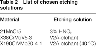
List of chosen etching solutions
X-ray diffraction
X-ray diffraction (XRD) was used to study the phases present after quenching with HIP, oil, and in the dilatometer. The analysis was performed by means of a Bruker D8 Advanced instrument (Cu Kα radiation). The specimens used were polished up to 1 µm and scanned over an angle of 30–95 2θ° with increments of 0.05 2θ° and a dwell time of 2 seconds. After the measurement, a Kα2 correction was applied and the background was subtracted.
Results and discussion
Cooling with URQ
Worldwide there are very few HIP units that provide with the URQ technique. Hence, characterisation of the cooling behaviour and cooling rates is of high interest. For this purpose, a parameter study was performed. The influencing parameters are depicted in the first part of this section.
Figure 3 shows that different cooling rates are possible to establish when a pressure of 100 MPa is applied. For natural cooling the heating elements are switched off without active cooling. The cooling rate is 40–70 K min−1. An even slower rate can be obtained by moderate use of the heating elements. The novel technique of URQ is labelled ‘Quenching'in Fig. 3. The fast-quenching in this case is achieved by pumping compressed cool gas inside the furnace chamber. A heat sink is installed to cool the gas being circulated by the compressor. It can be seen that the cooling rate is much higher, reaching values of about 700–850 K min−1 in this case. There are several parameters that influence the cooling rate. Firstly, different diameters of the gas inlet nozzle influence the mass flow.
Different cooling times are achieved with the different cooling mechanisms. The thermocouples measure the temperature of the gas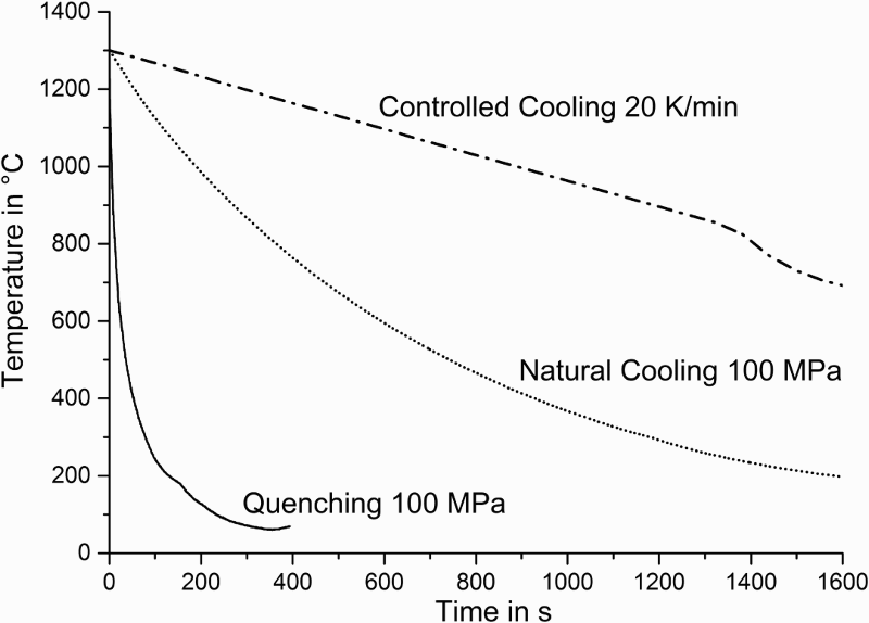
Cooling of a rod with a diameter of 30 mm and a length of 90 mm is shown in Fig. 4. Different nozzles are provided to achieve different cooling rates. It can be seen that a smaller diameter of the gas inlet nozzle for quenching is slowing the cooling rate of the specimen. At a pressure of 170 MPa and with a 6 mm nozzle, the core of the rod cools down from 1300 to 50 °C within about 5 minutes, whereas the cooling of the core takes more than 10 minutes when the 1.9 mm nozzle is installed. The medium nozzle of 3.2 mm provides a cooling time of about 8.5 minutes for the core. Figure 4 also shows that cooling of the gas near the specimen is influenced. That means the nozzle diameter is influencing the mass flow of the compressed gas.
Rapid cooling from 1300°C at 170 MPa and with different nozzle diameters. The cooled rod specimen has a diameter of 30 mm. One thermocouple is placed in the centre of the rod and another is placed in the gas at half the height of the specimen. The wider the nozzle diameter is, the faster is the cooling rate. The data of the cooling rate is smoothed with a rolling average (50 P)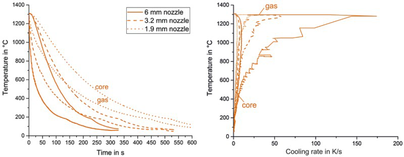
An increased mass flow increases the heat transfer. An increased gas velocity would also increase the heat transfer however, due to the high compression of the gas, there is no detectable acceleration of the gas flow when the nozzle diameter is reduced. Hence, a reduced diameter does not increase heat transfer by increasing the gas velocity. The cooling rates of gas and core are also depicted in Fig. 4. The figure shows that the maximum cooling rate for the gas more than doubles when changing the nozzle diameter from 1.9 to 3.2 mm, and more than triples when changing from 3.2 to 6 mm.
Figure 5 shows the cooling behaviour of three specimen geometries. The inner diameter of the furnace is 85 mm hence the specimen with 80 mm diameter is simulating a heavily loaded furnace, whereas the specimen with 30 mm diameter simulates a normal load. The 4 mm specimen represents a very small load. The influence of the specimen size can clearly be seen. Gas temperatures differ very early in the quenching process, and already from 900 °C onwards the core of the 30 mm specimen is cooled faster than the surface zone of the 80 mm specimen. The cooling of the 80 mm specimen reaches saturation at about 400 °C. The 4 and the 30 mm specimens can be quenched to room-temperature. The gas next to the 4 mm specimen is cooled only slightly faster than next to the 30 mm specimen. This leads to the expected conclusion, that the volume which can be rapidly cooled in the HIP is distinctly smaller than the furnace volume. The authors conclude that the material of the heat sink can take a limited heat quantity, which is reached in the case of the 80 mm specimen. Cooling of the 80 mm specimen in this case can be compared to cooling in a bucket of water that is too small. However, the device is built as a laboratory HIP and thus the specimen size is limited.
Rapid cooling at 170 MPa starting at 1300 °C. Two specimen geometries are compared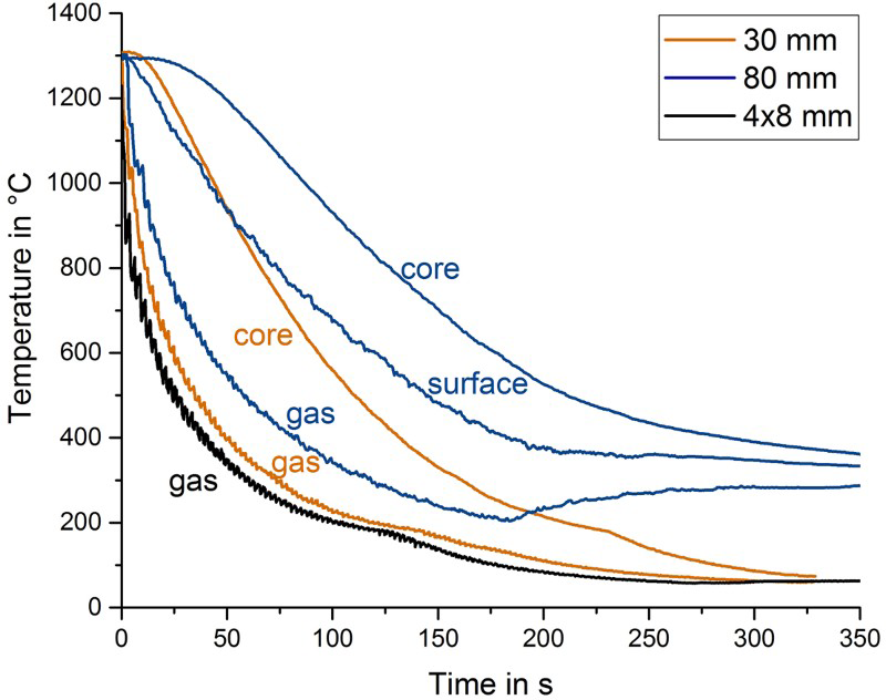
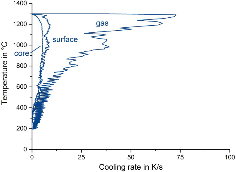
The cooling rates of the two larger specimens are shown in Figs. 6 and 7. The highest cooling rate of the gas near the 30 mm specimen is about double the rate of the gas near the 80 mm specimen. The gas reaches the highest cooling rate of about 85 K s−1 (5100 K min−1) in the range of 1250–1200 °C for the 80 mm specimen and a cooling rate of 180 K s−1 (10 800 K min−1) is reached between 1270 and 1230 °C for the 30 mm specimen. These cooling rates are very much higher than the cooling rates measured in HIP units with other fast cooling mechanisms. As previously described, other cooling mechanisms in a HIP unit reach 40–100 K min−1 at maximum.2–4 The core of the 30 mm specimen reaches the highest cooling rates of 11 K s−1 (66 K min−1) at 1200–1000 °C. For the 80 mm specimen the surface zone reaches a cooling rate of 8 K s−1 whereas the core reaches a rate of about 5 K s−1 also in the range of 1200–1000 °C.
Cooling rates of the gas and the core of the 30 mm specimen. The measurement is smoothed with a rolling average (50 P) Cooling rates of the 80 mm specimen measured in the core, surface zone and in the gas. The measurement is smoothed with a rolling average (50 P)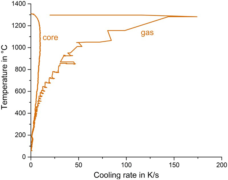
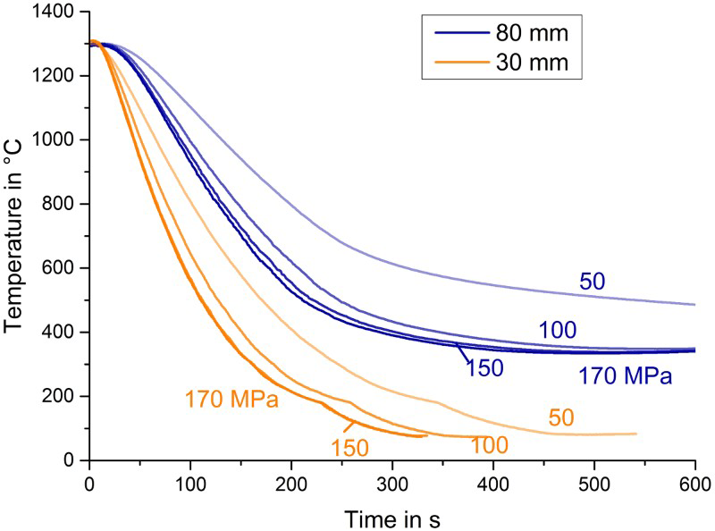
The last investigated factor influencing the cooling rate is the gas pressure. The intention of the URQ design was to utilise the strongly increased heat-transfer coefficient of highly pressurised gases. The heat-transfer coefficient is increased by the increased density and thermal conductivity due to the high pressure. The advantage of using liquids for cooling instead of to gases is the massively higher heat-transfer coefficient. The density of the cooling gas, in this case argon, increases with increasing pressure, thus reducing the difference in heat transfer between liquid and gas. The density of argon increases with increasing pressure and decreasing temperature. This is shown in Fig. 8. The measured cooling behaviour of specimens in this study is plotted in Fig. 9. It can be seen that cooling is strongly accelerated from 50 to 100 MPa. The difference between 100 and 150 MPa is now less pronounced, whereas in this study the difference in cooling time between 150 and 170 MPa is very small. This finding corresponds to the declining influence of pressure on the density of argon. Additionally, the viscosity of argon decreases with increasing pressure, which has a negative correlation with the heat transfer. Thus, the decreasing viscosity decreases the heat transfer, which leads to a saturation of the influence the argon pressure has on the increase of heat transfer.
Density of argon versus pressure at 1200 K and at 290 K. Data taken from [30] The influence of pressure on the cooling of the two specimen geometries. The data from the thermocouple inside the core is plotted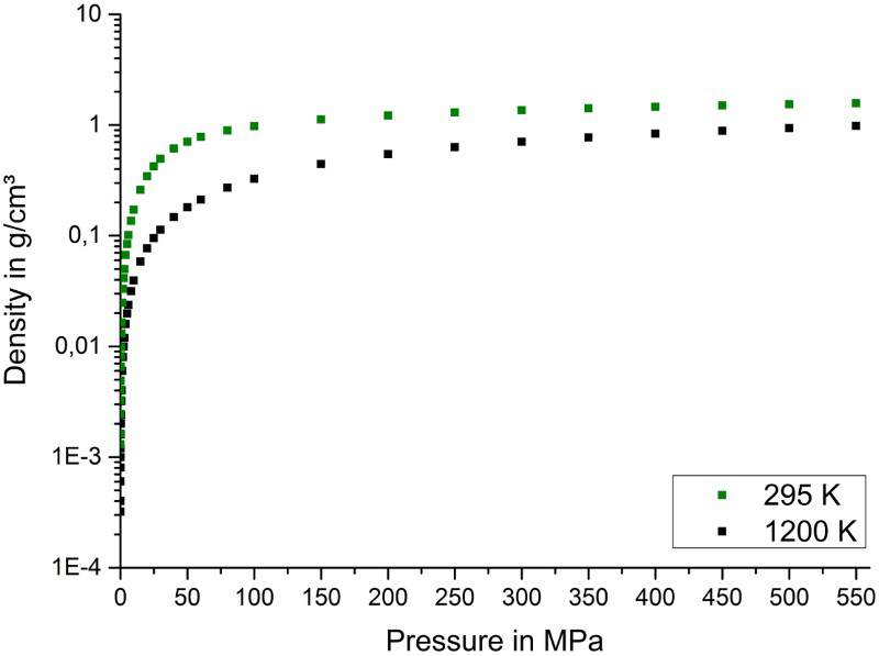
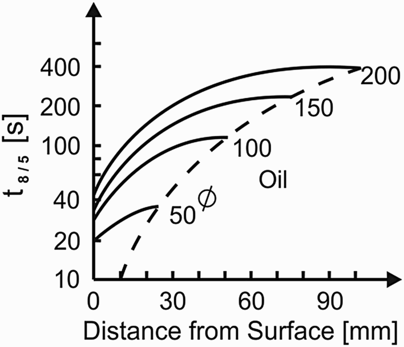
For the materials scientist, the heat-transfer coefficient, however, does not provide helpful information about the specific hardening process. As mentioned before, the t8/5 and t10/7 times are relevant for hardening without formation of pearlite/bainite or precipitation of carbides. Figure 10 displays the t8/5 time for quenching structural steel in oil. Naturally, the surface zone is cooled faster than the core. Information is taken from.12
t8/5 times for rods during oil hardening, redrawn from Berns and Theisen
12
For cooling in the HIP, this parameter was determined for the 30 mm specimen measured in the core and in the gas beside the specimen at half-height, which is shown in Fig. 11. The results show the influence of nozzle diameter and gas pressure on the time it takes the specimen to cool from 800 to 500 °C. With the 6 mm nozzle, it takes 45 seconds from 800 to 500 °C when 170 MPa is applied, and 69 seconds when 50 MPa is applied. When the smallest nozzle is chosen, the core takes 107 seconds from 800 to 500 °C at 170 MPa, but 162 seconds at 50 MPa.
Cooling time t8/5 measured at the specimen with 30 mm diameter, nozzles are varied between a 6, b 3.2 and c 1.9 mm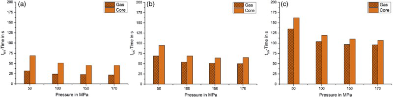
The t10/7 covers a shorter period of time because ΔT is larger. Figure 12 shows the times required for cooling between 1000 and 700 °C. In this case, the core takes 36 seconds when 170 MPa is applied in combination with the 6 mm nozzle, whereas it takes 82 seconds when the 1.3 mm nozzle is installed combined with 170 MPa.
Cooling time t10/7 measured at the specimen with a 30 mm diameter with a nozzle diameter of (a) 6, (b) 3.2 or (c) 1.9 mm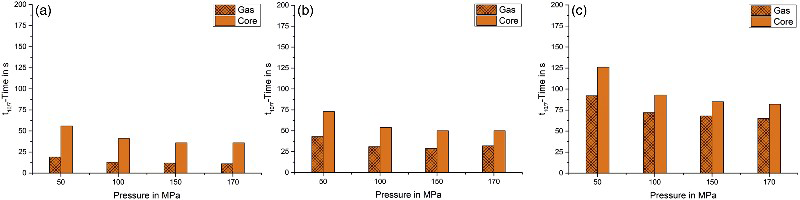
In order to compare these values with the values reached by cooling in a vacuum furnace, temperature measurements were performed with the same specimen during cooling in a vacuum furnace with 5 bar nitrogen gas. The results show that quenching inside the HIP is indeed faster than inside the vacuum furnace with 5 bar of nitrogen gas. This demonstrates the massively improved heat transfer of the compressed gas. Whereas the gas temperature in the vacuum furnace decreases much more rapidly the temperatures in the core are decreasing distinctly slower compared to HIP. A comparison of the t10/7 and t8/5 times is shown in Fig. 13. Cooling with 5 bar of N2 results in longer t10/7 and t8/5 times compared to 100 MPa in the HIP, whereas cooling can even be accelerated utilising higher HIP pressures, but also higher pressures in the vacuum furnace are possible. However, taking into account Fig. 10 it can be concluded that t8/5 takes longer in the HIP compared to oil-quenching. In this study several steel grades were quenched inside the HIP as well as in oil. The hardness and microstructure were compared and some positive effects of HIP-quenching were found that lead to overall similar or higher hardness values, even though the cooling rate is higher in oil.
Cooling of the same specimen in a vacuum furnace with 5 bar nitrogen and in the HIP with 100 MPa and the 6 mm nozzle. a and b show the 30 mm specimen, c and d show the 80 mm specimen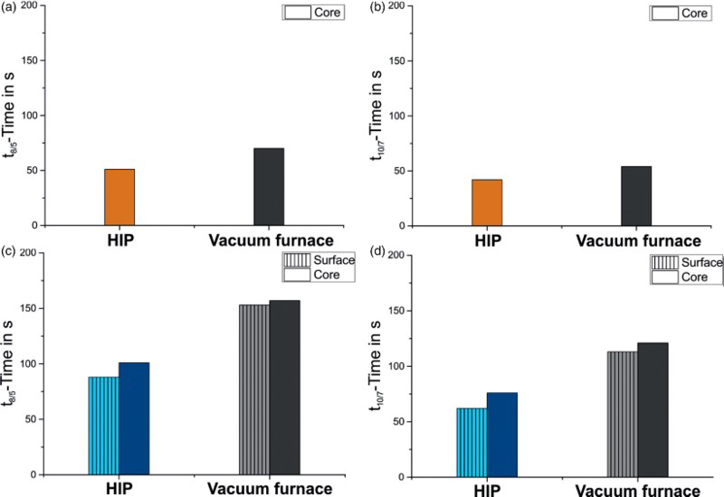
Influences on the microstructure
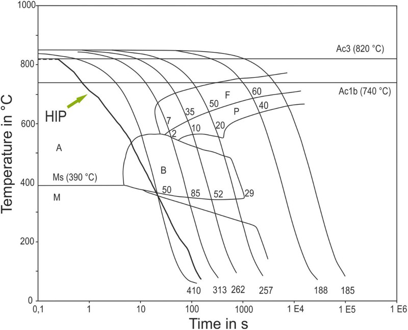
Several effects of high pressure on the microstructure during heat treatment of metallic materials were reported in the introduction. In the context of this study, effects of HIP heat treatment on the microstructure of steels were also found. First, a high pressure was found, to shift the phase transformation towards longer times and lower temperatures in the low-alloyed steel 21MnCr5 (1.2162). The steel had been quenched with the HIP, in oil, and as a dilatometry specimen with pressurised gas. The difference in hardness between the HIP specimen and the oil specimen amounts to about 60 HV30. The corresponding microstructures can be seen in Fig. 14. When the course of the temperature measured in the HIP, was simulated in the dilatometer, the difference in hardness decreases. The specimen hardened in the HIP is 25 HV harder than a specimen that was hardened with the exact same cooling rate in a dilatometer. Furthermore, the microstructure is finer after dilatometry than after quenching in oil, but more coarse than after quenching in the HIP. The TTT diagram of 21MnCr5 is depicted in Fig. 15. The HIP-quenching is faster at higher temperatures, probably because the Leidenfrost-phenomenon does not occur during gas quenching. The temperatures during quenching with HIP and with pressurised gas in the dilatometer were measured at the surfaces and followed the same course of temperature. As seen in the micrographs and in the TTT diagram, bainite formed during cooling. The HIP-quenched specimen features less bainite and also a finer bainite structure. The bainite is thus not only formed later in time, but also at lower temperatures at which nucleation is supported and diffusion is retarded compared to bainite formation at higher temperatures. This shows that the differences in TTT curves are not huge, but they are measurable and influence the hardness and microstructure in this case.
Light optical microscopy of a 21MnCr5 quenched with HIP; b 21MnCr5 quenched in oil; the austenitisation temperature was 840 °C in both cases TTT diagram of the 21MnCr5. The course of the temperature in the HIP was simulated with high pressure gas quenching in a dilatometer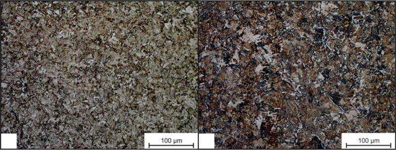
Another type of steel for which retardation of phase precipitation was demonstrated is X38CrMoV5-3 (1.2367). For this steel, the difference in hardness after quenching in the HIP compared to oil is about 50 HV. SEM micrographs reveal that the microstructure is purely martensitic with fine carbides. This means no other matrix phase, such as bainite or pearlite, has formed. The SEM micrographs are shown in Fig. 16. Since no softer phase has formed, the loss of hardness must be due to the loss of carbon in the martensitic lattice. It is concluded that pre-eutectic carbide precipitation is more pronounced during quenching in oil compared to quenching with HIP. The carbides seen in Fig. 16 are larger after oil hardening compared to HIP hardening. The authors conclude that carbide precipitation during quenching could have been retarded by the high isostatic pressure. A possible explanation is the stabilisation of phases with a lower molar volume by high pressures, as in.15,17 To specify the influence of pressure on pre-eutectic carbide formation the carbide precipitation has been promoted by holding at 700°C for 20 minutes after austenitisation.
SEM micrographs of X38CrMoV5-3 a quenched in HIP, b quenched in oil. The carbides are larger after quenching in oil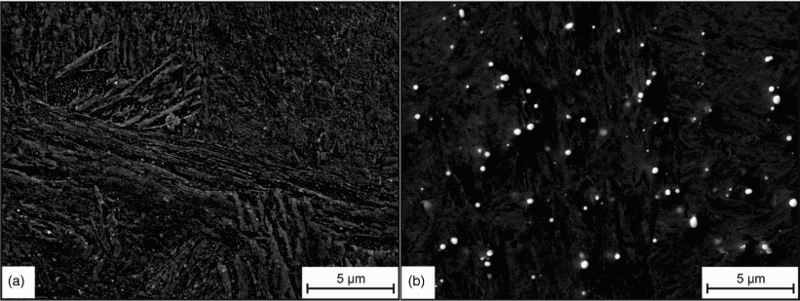
Again a temperature profile that had been measured in the HIP was imitated in the dilatometer by gas quenching. Both cycles included holding for 20 minutes at 700°C. The subsequent difference in hardness is about 35 HV, the HIP specimen being harder again. The microstructural investigation reveals more pronounced carbide precipitation for the specimen hardened in the dilatometer compared to HIP hardening. Additionally, carbide precipitates on the grain boundaries were found in the microstructure of the dilatometer specimen (shown in Fig. 17), but not in the microstructure of the HIP specimen. It can thus be concluded that formation of carbides had taken place during cooling or holding at 700°C in the dilatometer, but not in the HIP. Carbide formation withdraws carbon from the matrix, which results in a lower overall hardness.
Carbide precipitation on the grain boundaries of X38CrMoV5-3 after gas quenching in the dilatometer, including holding for 20 minutes at 700 °C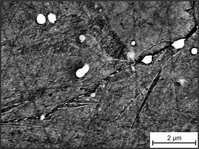
Pre-eutectic carbide precipitation is unwanted for several reasons. Mainly because carbides precipitated on grain boundaries cause brittleness and chromium-rich pre-eutectic carbides decrease the corrosion resistance,
13
but also because the consumption of carbon decreases the martensitic hardness. These results again show that a phase having a higher molar volume is suppressed in favour of the phase with the lower molar volume. The assumed change in precipitation kinetics during cooling is sketched in the TTT diagram of Fig. 18.
TTT diagram of X38CrMoV5-3 with a sketched line for the change of carbide precipitation when 170 MPa is applied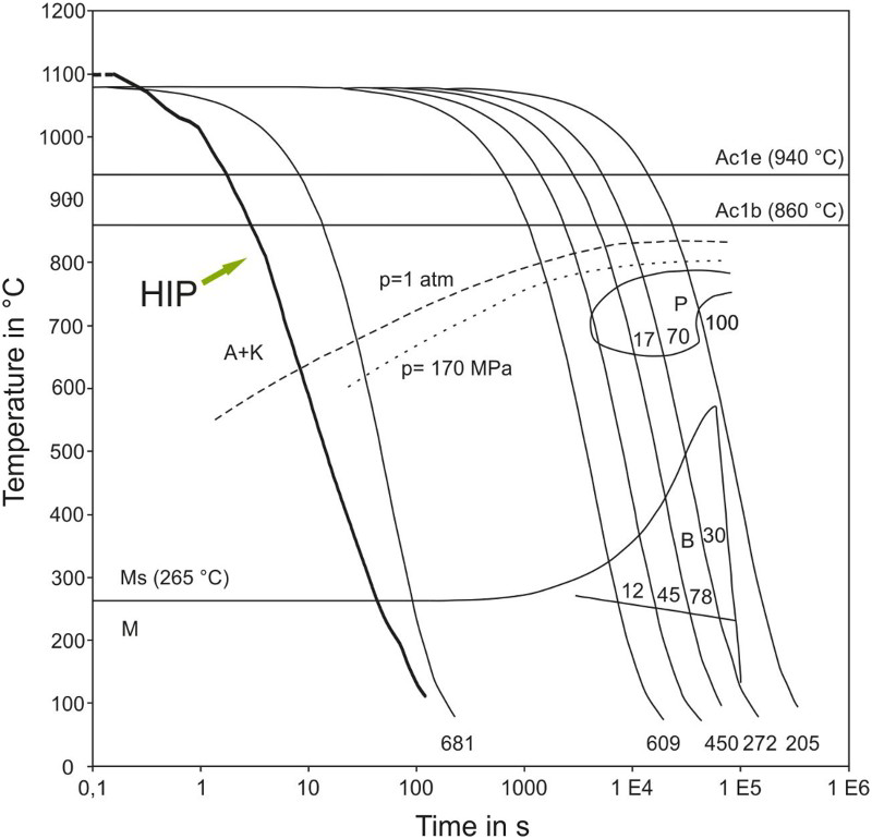
Not only the retardation of forming phases during quenching, but also the adjustment of a different thermodynamic equilibrium during the holding time at a high temperature can be observed when steel specimens are hardened in the HIP. When the X190CrVMoW20-4-1 steel is hardened in the HIP and in a regular furnace with oil-quenching, the hardness of HIP specimen is 115 HV higher. This apparently large difference in hardness diminishes to 7 HV after cryogenic treatment of both specimens. Cryogenic treatment is generally recommended for this steel. This shows that there was a higher amount of retained austenite in the specimen that was hardened in the regular furnace and quenched in oil. This assumption is supported by XRD spectrum (Fig. 19), which shows the reflexes of ferrite and austenite. The amount of retained austenite is considerably higher for the specimen subjected to the conventional heat treatment compared to HIP treatment. This steel contains two types of carbides, chromium-rich M7C3 and vanadium-rich MC carbide. The vanadium-rich MC carbide has a higher molar volume compared to the chromium-rich M7C3. At pressure this would result in a stronger dissolution of MC, whereas M7C3 is preserved. When no pressure is applied the dissolution of M7C3 is not retarded, which results in a higher amount of dissolved Cr and C. These two elements lower the martensite start and finish temperatures and could cause the higher amount of retained austenite. The small difference in hardness after cryogenic treatment shows, that it was not so much the carbon but rather the chromium that lowered the martensite finish temperature. When a high pressure is applied, the vanadium-rich carbides tend to dissolve to a greater extend and the chromium-rich carbides are stabilised. However, vanadium is not known to have a significant influence on martensite start/finish. The phase contents of the carbides are too small for changes to be seen in the XRD diffractogram.
XRD diffractogram of X190CrVMoW20-4-1 steel. The structure was examined after four different types of heat treatment, which revealed different amounts of retained austenite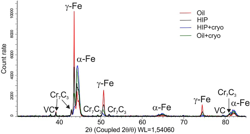
Summary and conclusions
This study investigates the characteristics of rapid HIP cooling achieved by circulating highly compressed gas that is cooled by a heat sink inside the pressure vessel. The t8/5 and t10/7 times between HIP cooling, gas cooling in a vacuum furnace, and oil-quenching were compared. The results show that the cooling in the HIP with the examined cooling technique is faster than cooling in a vacuum furnace, but not as fast as cooling in oil.
It was shown that increasing the diameter of the gas inlet nozzle increases the mass flow and significantly increases the cooling rates. Similar to every other cooling medium, the relation between the amount of heat that must be dissipated and the amount of heat that can be taken up by the medium must be appropriate to dissipate enough heat from the material being quenched. The influence of the gas pressure on the cooling rate was also investigated. The increase in the cooling rate at a gas pressure from 50 to 100 MPa was the strongest. Between 100 MPa and 150 MPa, there is still an increase, but it is less pronounced, and the difference between 150 and 170 MPa is marginal.
The hardening behaviour of small steel specimens subjected to HIP or oil-quenching was compared. Even though the cooling rate in oil is faster, the hardness of many different steel grades was of comparable hardness or harder after HIP-quenching. A microstructural analysis shows that the resulting bainitic structure is finer and a formation of pre-eutectic carbides is retarded. Furthermore, the thermodynamic equilibrium of the steel specimens was slightly shifted under high pressure.
The cooling rates are much faster than they had ever been in a HIP unit before. However, it is assumed that the cooling rates can be accelerated further by increasing the gas inlet nozzle diameter, changing working gas, and increasing gas velocity.
Footnotes
Acknowledgments
Financial support of the Deutsche Forschungsgemeinschaft (DFG) under contract of Transregio 103 is greatfully acknowledged.