
Abstract
During metal injection moulding (MIM) processing, titanium tends to react with carbon from the polymeric binder. Thus, carbides, which can effect embrittlement, might be formed if the carbon solubility of the alloy is exceeded. Especially in β-titanium alloys, this is a critical issue, because β-phase stabilising elements like V, Mo and Nb decrease the carbon solubility of the Ti-matrix. This study summarises studies with different approaches to limit carbide precipitation in a Ti–22wt-%Nb alloy processed by MIM. Adding Zr led to a significant reduction in the amount and size of carbides due to an increase in the lattice constant. Furthermore, boron was added supporting a finer distribution of the carbides. Scanning electron microscopy and transmission electron microscopy investigations reveal the role of the elemental additions and analyse the structure of the different carbides formed. Combinations with heat treatments led to significant reduction in the amount of carbides.
Introduction
Metal injection moulding (MIM) of titanium-based materials has become a more and more established manufacturing technology during the last decade [1,2]. However, commercial usage is still limited to Ti–6Al–4V and unalloyed titanium, although other alloys like Ti–6Al–7Nb, titanium aluminides and some β-titanium alloys have already been subjects of investigations [3–11]. The application of MIM for the processing of Ti–6Al–4V and unalloyed titanium is promoted by the existence of the corresponding ASTM standards F2885-11 and F2989-13, respectively. However, the demands in terms of chemical and mechanical properties require rather constant and high-quality processing conditions. Here, especially the uptake of the interstitial elements oxygen and carbon is of great importance, due to their well-known strong effect on mechanical properties. Equipment exclusively used for titanium processing is a good basis for high reproducibility of interstitial contents, but means rather high investments. Thus, MIM of titanium is still a critical process and the number of companies producing parts with constantly excellent properties is limited. To broaden number and fields of applications of this attractive cost-efficient technique, it is necessary to develop more robust alloys, which can tolerate varying content of interstitials in a better way. This means to understand their role in the material much better than today and find ways to extend their percentage allowed.
There is some work on the role of oxygen [12–15], but little is done concerning carbon [16], although it has to be discussed in the frame of binder development. Carbon is always present due to the usage of polymeric binders in MIM, so proper debinding is essential for the quality of the part. There are some recipes for binder composition and debinding available and, compared to oxygen, usually carbon content is not a severe issue in the case of unalloyed titanium or Ti–6Al–4V. The maximum carbon content defined by common standards is 0.08 wt-%, corresponding roughly to the solubility of carbon in a typical titanium matrix. This means that no carbides, which could have a detrimental effect on ductility, are precipitated during processing. However, it was shown that β-titanium alloys based on the system Ti–xNb reveal a significantly decreasing solubility of carbon with increasing Nb content, leading to the precipitation of carbides even at carbon contents below 0.08 wt-% [17]. The same is true for other β-titanium alloys based on V or Mo [18].
These carbides are located mostly at the grain boundaries and effect strong embrittlement. A decrease in plastic elongation of Ti–22Nb, from 11% to below 2.5% due to the forming of titanium–carbides along the grain boundaries, was shown and by transmission electron microscopy (TEM), and the carbides were identified as Ti2C [17]. Their length is up to 20 µm and more, and the width can be several micrometres, so they can be easily detected (see Figure 1). Carbide formation can happen if carbon solubility in titanium alloys is low or if carbon contamination during processing is too high. In the latter case, even unalloyed titanium or α–β alloys like Ti–6Al–4V and Ti–6Al–7Nb can be affected. Thus, finding ways to overcome the sensitivity of titanium materials for carbon is important for the processing of other alloys than Ti–6Al–4V and for more robust processing. The latter means also possible cost reduction by using low-cost powders or more simple equipment.
Ti2C precipitates at the grain boundaries of Ti–22Nb processed by MIM.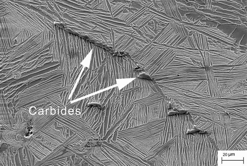
In this study, a summary of different investigations is given. The common goal of these studies was to minimise the formation of carbides in the alloy Ti–22Nb processed by MIM. In principle, the uptake of carbon is influenced by the type and percentage of binder as well as by processing conditions as sweep gas flow, sintering set-up and the furnace actually used. Experience of the authors shows that even the total number and the size of the parts and possible contaminations of the furnace by previous runs appear to affect the final contamination. However, to be more independent from specific facilities and processing conditions, in this study, only possibilities to reduce the amount of carbides by microstructural effects are discussed. Four different mechanisms (in the following referred to as approaches A–D), which could basically reduce the number of carbides by affecting microstructural changes, are investigated:
Performing appropriate heat treatments after sintering (A). Forming of other and smaller carbides than Ti2C by adding potentially carbon-binding elements (B). Creating more grain boundaries by microstructure refinement (adding of grain refiners) to form smaller and more distributed carbides (C). Increasing the carbon solubility by alloy modification (D).
As potentially stronger carbide former (approach B), Zr and Ta as biocompatible elements were chosen. According to the Ellingham diagram [19], these elements show similar or even higher affinity to carbon compared to titanium. This is also true for Nb, but the previous investigation mentioned above showed that even in Ti–22Nb just pure titanium carbides are formed [17]. However, in more complex systems like Ti–Nb–Zr or Ti–Nb–Ta, the Ellingham diagram may not be valid anymore in the shown form, so a trial was performed. For grain refinement (approach C), boron was selected, because previous studies showed its strong effect on colony size in Ti–6Al–4V [20]. Zr and Ta are also known as elements showing a widening effect on the titanium lattice [21]. Thus, potentially more space for interstitial atoms may enlarge the carbon solubility, which was tested in approach D.
Heat treatments (approach A) are attractive, because the previous study [17] revealed a varying solubility of carbon with temperature which can be exploited. Figure 2 shows the quasi-binary phase diagram Ti–22Nb–C, calculated by means of Thermo-Calc software [17]. Interesting is the increasing carbon solubility during cooling between 730 and 500°C. The phase diagram was proved experimentally using in situ high-energy X-ray diffraction. The shaded region designates the range of carbon content of the samples investigated in his work. So, quenching from the pure β region and heat treatment around 650°C could have a positive effect on carbide precipitation.
Calculated phase quasi-binary phase diagram Ti–22Nb–C [17].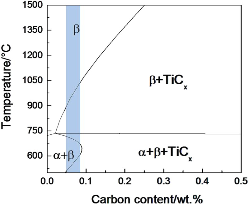
In the following, an overview on the results of the different approaches is given aiming at the identification of the most promising routes in terms of reduction in the amount of precipitated carbides. However, because the usage of elemental Ta powder as alloy addition turned out to lead to high porosities and the need of extremely high sintering temperatures (1600°C) due to slow diffusivity, results on Ta-additions were hardly comparable to the other specimens and, therefore, are not shown in this study. On the other hand, Ta revealed interesting effects worthwhile to be investigated in future studies.
Experimental
As base alloy in all experiments Ti–22Nb was used, produced by blending elemental powders and further MIM processing. In approaches B–D, elemental Zr and B powders, respectively, were added.
Materials
Materials used in the studies.

Sample production
The powders were mixed under argon conditions to the following different compositions (all in wt-%):
Ti–22Nb Ti–22Nb–10Zr Ti–22Nb–0.5B Ti–22Nb–10Zr–0.3B Ti–22Nb–10Zr–0.5B
After mixing the powder under argon atmosphere in a planetary mixer (Thinky, USA, ARE-250), it was blended with a binder consisting of 35 wt-% polyethylene vinyl acetate, 60 wt-% paraffin wax and 5 wt-% stearic acid. Two different types of samples were fabricated from the feedstock. For tensile test specimens (dog bone shape, ISO 2740), a mixture containing 10 wt-% binder was homogenised by means of a Z-blade mixer inside of a glove box system under controlled Ar atmosphere, extruded on an injection moulding machine (Arburg 320S, Germany) and granulated by means of a cutting mill. Then, the specimens were injection-moulded on the same machine. For cylindrical specimens intended for basic microstructure studies, a feedstock containing 8 wt-% binder was fabricated by means of the planetary mixer under argon. Subsequently, the feedstock was used for the production of the samples (8 mm diameter, about 12 mm height) by means of a simple manual press.
After green part production, the paraffin wax was removed by solvent debinding in hexane at 40°C for 900 min using a LÖMI, Germany, EBA 50 device. Thermal debinding and sintering took place in a Xerion, Germany, XVAC 1600 cold wall furnace, equipped with Mo shieldings and a tungsten heater. While thermal debinding was performed under slight argon flow at about 5 mbar pressure, sintering took place at 1500°C for 4 h under high vacuum (about 10−4 mbar) with subsequent cooling to room temperature (10 K min−1). The same furnace was used for the heat treatments, besides the water-quenched samples which were annealed in a simple muffle furnace (Nabertherm, Germany) under air.
Analyses
Chemical analysis
For the determination of the carbon content, a LECO, USA, CS-444 device was used, whereas oxygen was analysed by the application of a LECO TC-436 device.
Microstructure
Both an optical microscope (Olympus PMG3, Japan) and a scanning electron microscope (SEM; Zeiss, Germany, Leo 1530 Gemini) were used for microstructural examination. Specimens were cold-embedded and prepared by wet grinding with SiC papers in grit sizes from 320 to 2500 followed by polishing with 3 μm diamond paste and neutral Struers OP-S suspension.
Compositional analysis was done with energy dispersive spectroscopy (EDS) using the EDAX system. EDS spectra were collected at an accelerating voltage of 15 kV and a measuring time of 100 s.
Optical micrographs were used for the calculation of carbides and other precipitates. Their phase fractions (area%) were determined with the analySIS pro software (Olympus Soft Imaging Solutions). To distinguish between pores, carbides and borides, in special cases, manual image editing like retouching pores was performed. Carbide quantity was determined as an average of two images.
TEM observation was carried out by Philips, Netherlands, CM200 Electron Microscope operated at 200 kV. TEM samples were prepared by focused ion beam (FIB) (Zeiss FIB Auriga, Germany). During FIB sample preparation, the beam current was applied in a step-down fashion such as from high current to low current in order to remove any damaged layers from previous operations.
Porosity was measured by Archimedes' principle with a respective set-up on a Sartorius, Germany, Masterpro scale. Then, porosity P was calculated using the following equation:

X-ray diffraction
For X-ray diffraction (XRD), a Siemens, Germany, D5000 diffractometer was applied. The measurements were carried out on the rotating samples using CuKα radiation (0.15418 nm) at 40 kV and 40 A. Specimens were ground before the measurements to obtain a clean surface. Diffractograms were classified using the PDF2002 database of the International Centre for Diffraction Data (ICDD).
Grain size
Because, in some cases, the grain boundaries were hard to identify on optical or SEM images, electron backscatter diffraction (EBSD) was applied. For this a Zeiss, Germany, Ultra 55 was used. An area of 2000 × 3500 μm2 was measured at 15 kV for 19 h. In all cases, grain size was determined with a linear intercept technique using the analySIS pro software.
Investigations
Different heat treatments were performed on as-sintered Ti–22Nb samples. Based on the calculated quasi-binary phase diagram (Figure 2), the approach was either to quench from high temperatures (pure β region) or to resolve already formed carbides at a temperature around 650°C where the phase diagram shows maximum solubility of carbon. The following experiments were performed:
Annealing at 1300°C for 2 h with subsequent fast cooling to room temperature by shutting off the heater completely (continuously decreasing cooling rate, with an average of 75 K min−1 down to 900°C). Same as before, but fast cooling just down to 650°C, then holding for 10 h and subsequent fast cooling to room temperature. Annealing in a muffle furnace under air at 1300°C for 10 min and subsequent water quenching. TEM and EDS investigations were performed on Ti–22Nb–10Zr samples in order to check, if other carbides than Ti2C can be found. The effect of boron addition on grain refinement and carbide reduction was investigated on Ti–22Nb–0.5B samples. The influence of Zr on the amount of carbides formed was the subject of this experiment. Besides the microstructural characterisation, XRD measurements were performed to investigate a possible induced change in the lattice parameter of the titanium matrix by the addition of Zr. This investigation was performed on Ti–22Nb and Ti–22Nb–10Zr specimens. Based on the results of the experiments A–D, combinations were investigated: adding boron and zirconium to form the compositions Ti–22Nb–10Zr–0.3B and Ti–22Nb–10Zr–0.5B and applying heat treatments on both of these alloys.
Results and discussion
Figure 3 shows the microstructures after the different types of heat treatments focusing on the amount of carbide precipitates. In all cases, the residual porosity was determined to be around 4.7%. The oxygen content was between 0.27 and 0.30 wt-%. Table 2 lists the measured values for the total carbon content, the carbide amount and the grain size. Furthermore, deduced from SEM images and EDS analyses, the percentage amount of β-phase and the Nb concentration in α-phase are inserted. The water-quenched sample was heat-treated under air, and carbides and grain size were too small to be compared. Therefore, no values are shown in the table. However, Figure 3(d) reveals the strong effect of this treatment. It has to be noted that this image is taken with higher magnification than Figure 3(a–c).
Optical micrographs of (a) Ti–Nb22 as sintered, (b) annealed at 1300°C/2 h and fast cooled, (c) fast cooled to 650°C/10 h and (d) annealed at 1300°C for 10 min and water quenched. The black features are pores, while the middle grey ones represent carbides. Results of heat treatments applied to Ti–22Nb.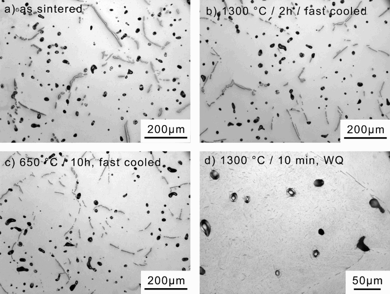
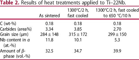
The results show clearly that heat treatments can significantly influence the precipitation of carbides. The strongest effect is visible after water quenching. In this case, diffusion is too slow to form large carbides; however, it is not possible to completely suppress their precipitation as shown in Figure 3(d). On the other hand, during commercial production, water quenching is hardly applicable and simple fast cooling does not result in carbide reduction as shown in Figure 3(b). It even seems to enhance precipitation. This might be due to the very high total carbon content of the samples: according to the calculated phase diagram, even at 1300°C, the carbon might not be completely resolved and additional heating might promote further precipitation. Nevertheless, heat treatment at 650°C appears to be an adequate method to at least reduce the number and size of carbides. In Table 2, grain size is only slightly influenced by the heat treatments applied. In contrast, a great influence on the Nb content in the β-phase and the amount of β-phase is visible. Without heat treatment at 650°C, the Nb concentration is far away from a value around 5 at.-% predicted by the binary Ti–Nb phase diagram. At this temperature, the diffusivity of Nb is too low to enable the atoms to leave the α-phase during cooling. This means that the material is far away from thermodynamical equilibrium which could also affect the mechanical properties. The overall amount of β-phase is lower than expected for a metastable β-alloy. It can be assumed that this is due to the high carbon content stabilising the α-phase.
Even if the data from the Ellingham diagram reveal a small chance to find stronger carbide formers than titanium, in the sintered Ti–22Nb–10Zr alloy, TEM and EDS analyses gave no evidence that mixed carbides or pure Zr-carbides exist. Figure 4(a) shows a micrograph of the alloy. Compared to Ti–22Nb, the porosity increased to about 5.7% due to the addition of elemental Zr powder impeding the diffusion processes responsible for sintering. Furthermore, the carbides appear to be smaller than those displayed in Figure 3(a), and more detailed investigations showed that tiny precipitates distribute over the titanium matrix. In Figure 4(b), it can be concluded that the carbon-enriched phase has an fcc structure with superlattice diffraction spots, identified by serial tilting operation. Its lattice parameter ranges from 0.432 to 0.436 nm, which is higher than 0.429–0.430 nm (carbides in Ti–22Nb). The results of the EDS analysis summarised in Table 3 reveal that the Zr content is the same in matrix and carbides. TEM and EDS analyses show that the carbides in Ti–22Nb–10Zr have the same crystal structure as Ti2C in Ti–22Nb [17]; just some Zr-atoms are dissolved and the lattice constant is increased by around 8%. Nb is also found in the carbides, but in a significantly lower amount than in the matrix. In summary, no formation of pure Zr- or Nb-carbides could be observed, so the approach of using other carbide formers appears to be unsuccessful.
(a) Optical micrograph of Ti–22Nb–10Zr as sintered, (b) TEM-BF image and selected area diffraction pattern of a carbide. Results of EDS measurements on the carbide shown in Figure 4(b).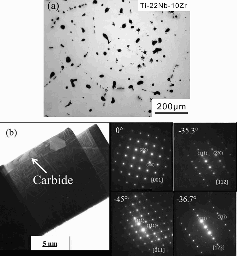
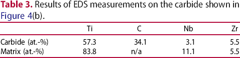
Figure 5 shows a comparison of the carbides formed in Ti–22Nb and Ti–22Nb–0.5B. It is clearly visible that in the latter case, the carbides tend to be reduced in size and to distribute little more. However, porosity increases somewhat. Moreover, borides seem to form agglomerates that can be attributed to insufficient mixing of the elemental powders and slow diffusion. From the analysis of more micrographs, it can be estimated that by adding 0.5 wt-% B, the grain size is reduced to about 70% of the value of pure Ti–22Nb and the carbide area fraction is reduced to about 0.4%. However, the specimens in that investigation showed a rather low total carbon content between 0.5 and 0.6 wt-%. Thus, direct comparison to the results mentioned before is not possible. In addition, the carbon concentration is possibly close to the carbon solubility of the alloy (cf. Figure 2), so small changes in carbon content may have a strong effect on the precipitation of carbides. Furthermore, it is rather difficult to distinguish between carbides and borides in the micrographs resulting in some uncertainty of the numbers. To sum up, it appears that there is an effect on carbide precipitation by grain refinement, but to what extent cannot be concluded from this study alone.
Effect of boron addition on carbide precipitation; (a) Ti–22Nb and (b) Ti–22Nb–0.5B.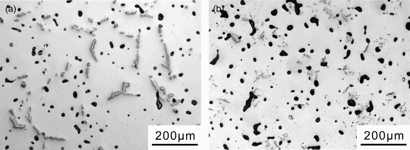
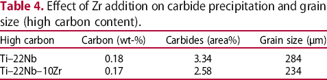
Effect of Zr addition on carbide precipitation and grain size (high carbon content).
Effect of Zr addition on carbide precipitation and grain size (high carbon content).
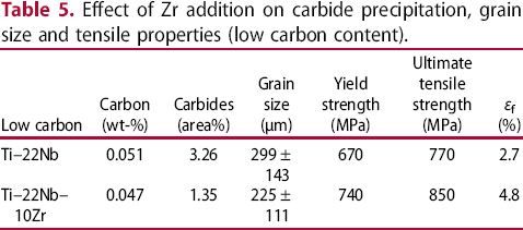
Effect of Zr addition on carbide precipitation, grain size and tensile properties (low carbon content).
The reduction of the amount of the precipitated carbides is assumed to be due to the expected effect of Zr to enlarge the lattice constant of the titanium matrix. This effect was already shown in the case of the TEM investigations of the carbides. The XRD measurements prove an increase in the lattice parameters estimated to about 1% in β-phase and 0.6% in α-phase. Figure 6 reveals the visible shift of the peaks.
Comparison of XRD patterns performed on Ti–22Nb and Ti–22Nb–10Zr. Visible is a shift of the α- and β-peaks revealing a widening of the lattice parameter by Zr addition.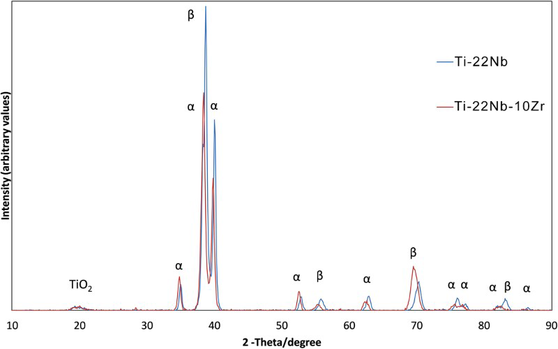
Most β-stabilising elements lower the lattice parameter of β-Ti alloys result in carbide precipitation on the grain boundaries [16,22,23]. However, TEM analysis reveals an increase again by Zr from 0.328 nm in Ti-22Nb to 0.331 nm in Ti–22Nb–10Zr. It can be assumed that, by this, carbon solubility increases and the carbide precipitation starting temperature lowers as seen in this study; thus, carbides become fewer and smaller. So, zirconium addition appears to be an adequate means to reduce the amount of carbides. Furthermore, it increases the strength of the alloy by solution hardening and shows a slight grain refinement effect (Table 5).
In Figure 7, EBSD images of the as-sintered microstructure of Ti–22Nb, Ti–22Nb–10Zr, Ti–22Nb–0.3B and Ti–22Nb–10Zr–0.5B are shown. Two things are obvious: (1) porosity increases with the addition of elemental Zr and B powders, probably due to more complex diffusion processes and (2) boron addition results in grain refinement. Table 6 lists grain size, porosity, carbide area fraction and total carbon content depending on the alloy.
EBSD images of (a) Ti–22Nb, (b) Ti–22Nb–10Zr, (c) Ti–22Nb–0.3B and (d) Ti–22Nb–10Zr–0.5B alloys, demonstrating the grain refinement effect of Zr and B. Results of grain size, porosity, carbide area fraction and total carbon content measurements on samples with Zr and B addition.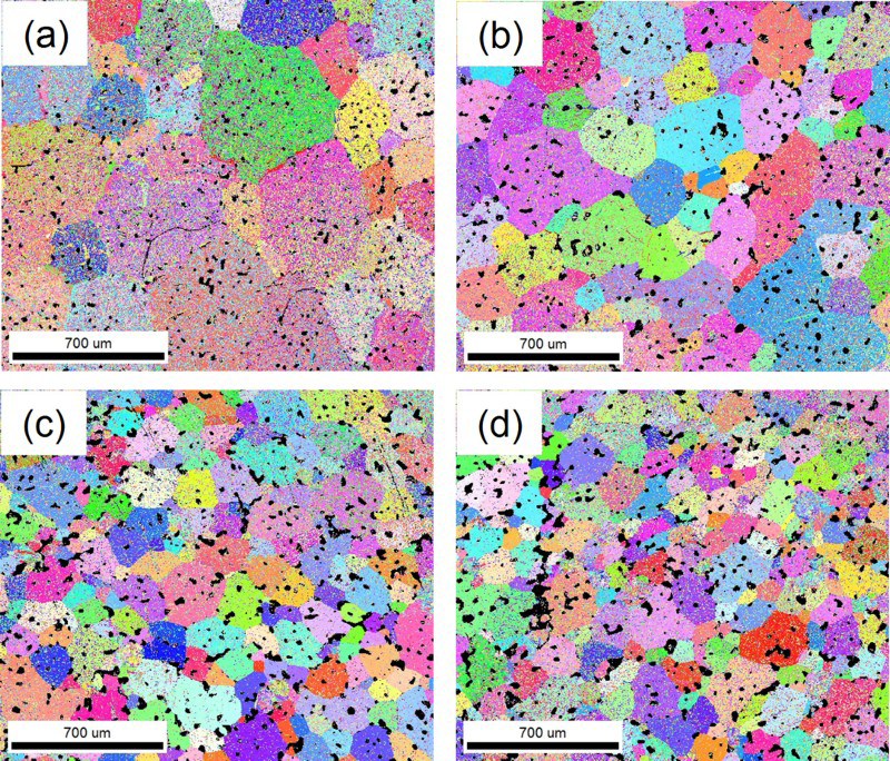
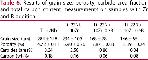
There is a significant reduction in the carbide area fraction by the combination of Zr and B, even if considering the lower carbon content of the boron-containing samples. Table 5 summarises that a high amount of carbides is expected even for Ti–22Nb with similar low carbon content, so the combination of Zr and B appears rather effective.
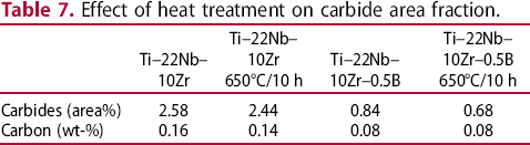
From the results discussed, the application of a heat treatment at 650°C for 10 h, following by fast cooling to room temperature, appears to be attractive for further improvement. Indeed, in Table 7, this heat treatment reduces the amount of carbides further. While the effect in pure Ti–22Nb–10Zr is visible but limited, in the Ti–22Nb–10Zr–0.5B alloy, it is significant. Instead of more than 3% carbides, a value of about 0.7% is reached by the combination of Zr, B and heat treatment. Figure 8 displays two micrographs of the two boron-containing alloys, revealing that only few carbides are visible compared to Ti-22Nb (Figures 3(a) and 5(a)). However, the agglomeration of borides and the rather high porosity prove that further improvement in the manufacturing process is necessary. It can be assumed that, for example, using pre-alloyed powder will lead to significantly more homogeneous microstructures.
Microstructures of heat-treated (650°C/10 h) Zr- and B-containing specimens; (a) Ti–22Nb–10Zr–0.3B and (b) Ti–22Nb–10Zr–0.5B. Agglomerations of borides and small carbides, mainly at the grain boundaries, are visible. Effect of heat treatment on carbide area fraction.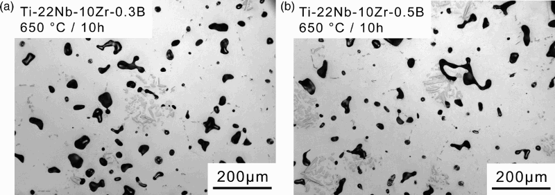
Conclusions
From the results of the discussed studies, it can be concluded that there are different ways to reduce the amount of carbides in titanium alloys, especially β-titanium alloys. They can be divided into heat treatments and alloy modifications. A kind of ranking could be the following:
Quenching or fast cooling is the most effective way for carbide reduction; however, it is hard to realise for commercial products. Heat treatment around 650°C is effective to resolve carbides formed during cooling and can be performed after sintering in a large batch of samples. Addition of Zr increases the carbon solubility and lowers the carbide precipitation starting temperature, which reduces the amount and size of carbides. Furthermore, strength is increased and grain size reduced. Gain refinement by boron addition has a significant effect on carbide forming, especially in combination with Zr addition. Trials to bind carbon to other elements were not successful, yet.
By combinations of these methods, a typical value of 3.3% carbides can be reduced to 0.7% using a heat-treated Ti–22Nb–10Zr–0.5B alloy. However, the effect on mechanical properties has to be investigated in future studies. In addition, using pre-alloyed powders instead of elemental is recommended to avoid increasing porosity.
Footnotes
Notes on contributors
Disclosure statement
No potential conflict of interest was reported by the authors.