
Abstract
AZ91 magnesium alloy parts were successfully produced using a novel extrusion-based additive manufacturing process. The green parts were built in two different orientations and subjected to debinding and sintering treatments. The as-built alloy showed a heterogeneous microstructure made up of α – Mg matrix, Al8Mn5 second phase particles, MgO layers and Mg17Al12continuous precipitates. After solution treatment followed by aging, Mg17Al12 discontinuous precipitates were observed. The sintered samples showed a yield strength and ultimate tensile strength of 79 and 207 MPa, respectively, in the horizontal configuration. Analysis of the fracture surfaces revealed that a continuous network of magnesium oxide layer around the powder particles act as preferential path for crack propagation.
Introduction
Extrusion based Additive Manufacturing (EAM) of metals is a relatively novel processing technique involving layer-by-layer deposition of feedstock material available in the form of pellets or filaments. The feedstock material is made of metal powder and polymeric binder. 3D printed parts are then processed through subsequent debinding and sintering steps, similar to those followed in powder injection moulding [1–3]. The major advantage of this technique is the near-net-shape processing in a single step, thus eliminating the need of machining. Another advantage is the ease of processing complex shapes and parts, which are extremely cumbersome to produce by conventional processing techniques [4].
Fused Deposition Modeling (FDM) is an additive manufacturing technique where filaments of a build material and a support material are extruded together layer-by-layer, according to a pre-programmed trajectory [5]. This technique is more commonly used to produce polymer products, however, several metallic products and ceramics have already been explored [6] [6,7]. To produce metallic or ceramic products by FDM, the feedstock is a mixture of a powder and polymeric binder. The binder provides adequate viscosity for extrusion while also acting as a support for the extrusion of the green part. The feedstock then passes through the extruder that plasticises the material before finally passing out of the nozzle. Once the feedstock is deposited layer-by-layer, the green part undergoes debinding and sintering. This ensures good metallurgical bonding of the powder material [8]. A major advantage of FDM is that it is the most economical process available in the market [9].
Magnesium is the lightest structural element in use with a density of 1.74 g cm−3 [9]. In comparison, iron, the most used element for structural applications has a density of 7.87 g cm−3, which is nearly five times heavier [9]. This could prove to be an economical choice for automotive and aerospace applications. Joost in [10] has documented that a 10% reduction in vehicle weight provides a 6–8% improvement in fuel economy [10]. Another application for Mg-alloys is the medical industry due to the high biocompatibility of this metal. Mg–Ca, Mg–Zn, Mg–Sr are suitable systems commonly used for such applications [11,12].
Among the wide variety of available Magnesium alloys, the AZ91 is the most used for structural applications due to its superior castability, corrosion resistance and mechanical properties in comparison to other Mg alloys [13]. The enhanced strength is due to the microstructure, which consists of α-Mg matrix and precipitates of Mg17Al12 [14].
Processing of Mg alloys through conventional metal additive manufacturing processes, such as Selective Laser Melting (SLM), has a number of drawbacks and limitations [15]. Mg has an extremely high affinity towards oxygen, especially in the liquid phase. Magnesium powders are also prone to dust explosions and their handling and storage is a crucial step for the production of parts. AZ91D parts produced by SLM have also displayed poor ductility with a maximum elongation at fracture between 1.24 and 1.83% [15]. EAM of magnesium powders, premixed with a polymeric binder, allows to avoid technological and safety risks associated with SLM. Previous studies concerning Metal Injection Moulding of magnesium have indicated two main challenges, the first regarding the binder that should not react with the powder and should be removable at rather low temperatures before sintering starts, the second regarding the sintering itself, which can be aided by liquid phase. The work of M. Wolff in ref. [16] reports the main issues related to sintering of Mg and the effect of Ca addition.
This study aims to investigate the microstructure and mechanical properties of Mg alloy AZ91 produced by EAM. The novel process is complementary to metal injection moulding (MIM). While MIM is for mass production with high tooling costs but low part costs, EAM is adequate for prototypes, customised parts and small series production.
Microstructure of as-sintered and heat-treated parts are investigated by X-ray diffraction (XRD), Electron microscopy and thermal analysis. Mechanical behaviour of sintered parts was evaluated by Vickers microhardness and tensile tests.
Experimental procedure
The AZ91 alloy powder was produced by gas atomisation at SFM SA in Martigny, CH. The powder particles have a maximum size smaller than 45 μm. The feedstock (powder + binder mixture) was produced at Helmholtz-Zentrum Geesthacht in Germany. The feedstock has AZ91 alloy powder loaded at 64 vol.-% into polymeric binder.
The feedstock was 3D printed in form of rectangular bars by a specially developed EAM machine as shown in Figure 1(a). Machine capabilities and operations were demonstrated in earlier works [2,17]. More information about binder composition can be found in ref. [18].
(a) Extrusion based additive manufacturing (EAM) machine with principle components (b) Nozzle used in this study φ 0.8 mm.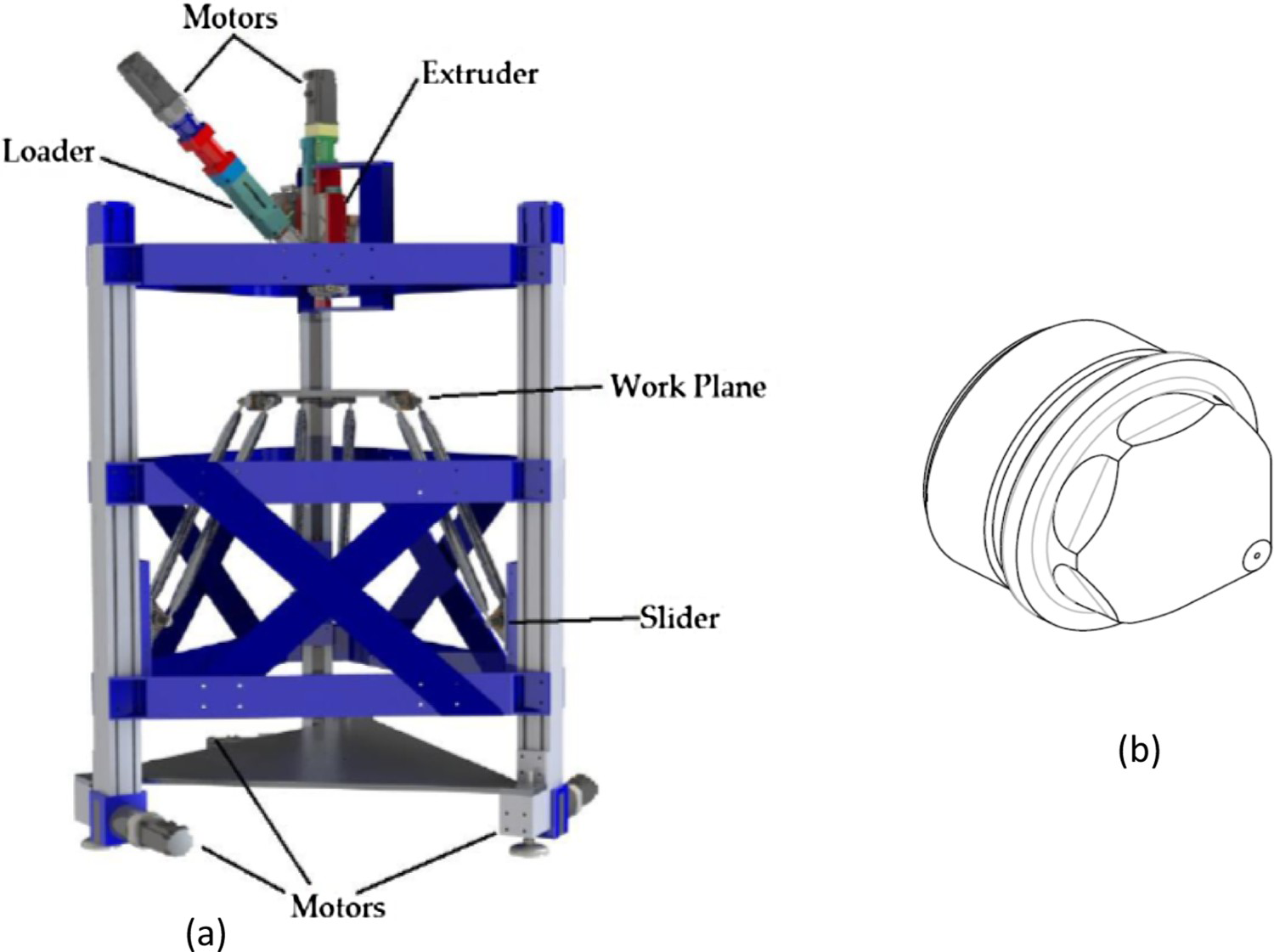
The work plane is free to move in directions X, Y and Z and it is governed by a 3-axes parallel kinematic system (Linear Delta) operated through three stepper motors as shown in Figure 1(a). The printing head is fixed and is composed by a feeder, where the pellets of feedstock are placed, a screw plasticiser and an injector piston. In the extruder system, the feedstock is loaded into the feeder and falls by gravity in a first loader chamber, which plasticises the material, and is then injected in a second extruder chamber, which directly provides a molten feedstock to the nozzle for deposition on work plane. A PLC controls loading, printing and temperature at three different locations, including the exit nozzle. The input is given by loading a g-code file generated using the shareware Slic3r software.
12 bars (6 mm height, 60 mm length and 10 mm width) were printed in a ‘horizontal’ configuration, laying on the face of dimensions 60 × 10 mm, and a ‘vertical’ configuration, laying on the 60 × 6 mm face. The printing parameters, namely nozzle diameter of 0.8 mm, extrusion temperature of 150°C and extrusion velocity of 7.5 mm s−1 were kept constant for all the experiments. The printing speed, i.e. the horizontal velocity of the printing table, was selected by setting an extrusion multiplier of 0.75, defined as the ratio between extrusion velocity and printing speed. In other words, with a printing speed of 10 mm s−1, the material flows out of the nozzle at an extrusion speed of 7.5 mm s−1. The samples were 3d printed with a theoretical full density at the green state. However, it is well known that the EAM process always induces some porosity, i.e. leaves some empty space between adjacent tracks.
After the production of the green part, the solvent debinding was done using hexane. The final densification was achieved by sintering at 605°C for h. Then, the as-sintered part was cooled in the furnace to room temperature. Further processing details can be found in [18].
The samples were cut and were subject to solution annealing at 415°C for 16 h, followed by quenching in water. Rapid non-equilibrium heating has known to induce void formation by the melting of eutectic precipitates in Mg–Al alloys [19]. Therefore, samples were heated by linear ramp from 260 to 415°C over a time period of 2 h according to the ASM Handbook Volume 4E [19].
The solution-treated samples were further subjected to aging treatment at 168°C for 16 h according to the ASM Handbook Volume 4E [19]. Microhardness measurements were carried out using the Future-Tech FM700 fitted with a Vickers indenter. Loads of 50 g and 500 g were used with a dwell time of 15 s.
After the aging treatments, all the samples were ground and polished using diamond paste. The microstructures of the samples were observed under an optical microscope (Nikon Eclipse LV150L) and Scanning Electron Microscopy (SEM) (Zeiss Evo 50 and Zeiss Gemini) equipped with EDX detector (Oxford Instruments model 7060). The samples were etched using a 2% Nital solution. To quantify the porosity, five images of the as-sintered sample were analysed using the ImageJ software. XRD analyses were carried out by Rigaku SmartLab SE. Diffractograms were analysed by QualX software and COD database. Thermal analysis was carried out by Labsys TG-DSC by Setaram instruments. The samples with a mass of about 40 mg were heated to a temperature of 700 °C at a rate of 20°C min−1, held there for 300 s, and cooled to room temperature.
Three tensile tests were carried out on as-sintered and peak-aged samples. Standard specimens were milled with gauge length of 25 mm, thickness of 3 mm and width of 6 mm according to the ASTM standard E8/E8M. The tensile test was conducted on an MTS Alliance RT/100 3.7 at a deformation rate of 1 mm min−1.
Results and discussions
The AZ91 samples were successfully prepared using an extrusion-based additive manufacturing process. Both the vertical and horizontal builds were produced and sintered according to the procedure reported in the experimental section. The green parts are illustrated in Figure 2(a,b,e and f). The samples prepared do not have any coarse defects under visual examination at their outer surface, except for the inherent waviness due to the overlap between adjacent 3d printed tracks. The as-sintered samples are shown in Figure 2(c,d,g and h). The shiny surface implies that the sintering has been successful. The layers were distinctly visible on the lateral surfaces, whereas extrusion tracks were noticeable on the top surfaces.
(a), (b), (e), (f) as built (before sintering) specimens and (c) (d) (g) (h) as sintered specimens.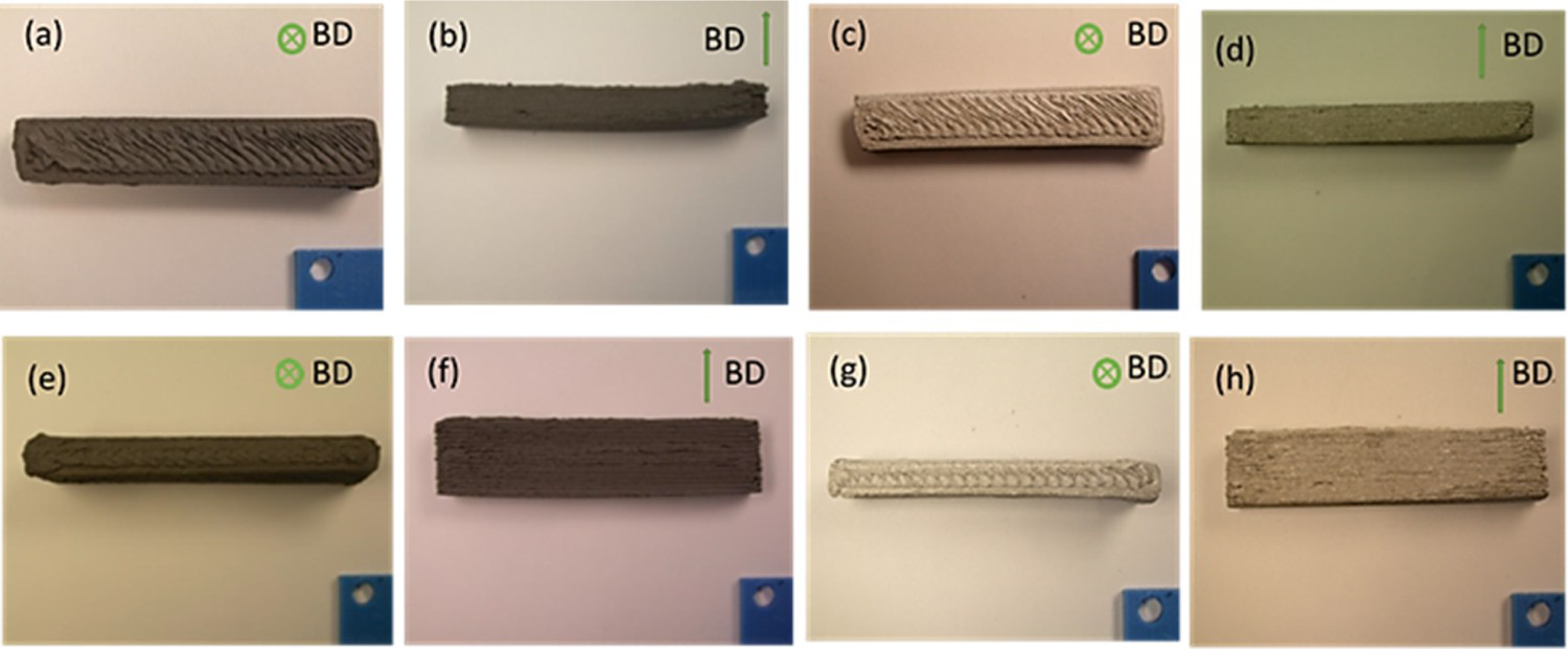
The XRD diffractograms of the as-sintered, solution treated and aged samples are shown in Figure 3. In the as-sintered alloy, three sets of peaks were observed. The most intense peaks were identified as the main reflections of the α-Mg, which is the matrix phase of the alloy. Peaks related to Al8Mn5 and MgAlFeO4 phases were also identified. Peaks corresponding to Mg17Al12 in the as-sintered sample were also expected. Indeed, Mg17Al12 precipitates might form on cooling from the sintering temperature. However, no peaks related to such phases were detected. This does not exclude their presence in the as-sintered samples, since their content could be lower than the minimum fraction that can be detected by XRD analysis. After the solution treatment, there is a subsequent increase in the intensities of the oxide peaks. The isothermal aging results in the formation of Mg17Al12 precipitates. The peak intensity was observed to be very small with respect to that of α-Mg. These results are in accordance with the work conducted by Mondet et al. [20], where AZ91 alloys were prepared by Spark Plasma Sintering (SPS).
XRD patterns of AZ91 after different heat treatments.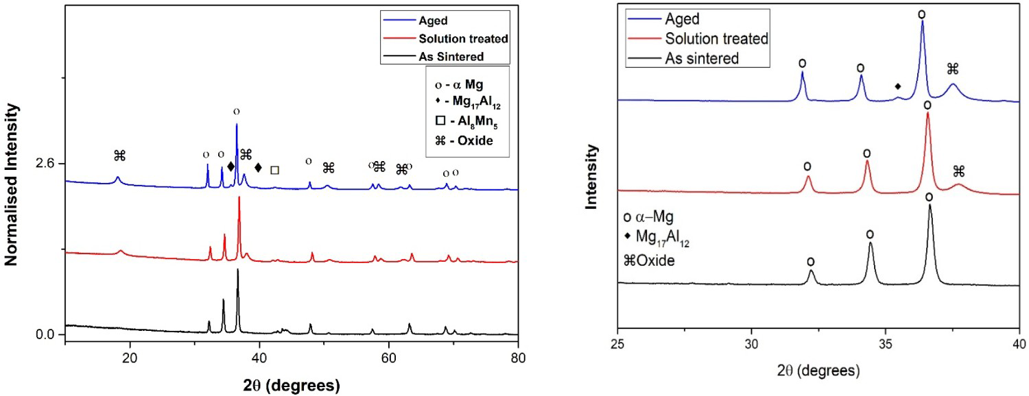
DSC curves of as-sintered and solution treated samples are shown in Figure 4. On heating, two peaks were observed. These are marked as 1 and 2 in Figure 4. Both the as-sintered and the solution treated samples had similar heating curves, and the same set of peaks were observed. At around 430°C, the first peak is observed. This corresponds to the melting of the eutectic product Mg17Al12 [21]. The second peak was observed at approximately 610°C, which corresponds to the melting of α – Mg. Although an endothermic peak was expected for dissolution and precipitation of Mg17Al12, it was not observed. The observations, however, are consistent with the studies conducted by Ohno et al [21]. The melting of the eutectic is at around 430°C is crucial, as it could possibly induce porosity during annealing. From this curve is also evident that the sintering of samples at 605°C occurred in the semi-solid state.
DSC curves of the as sintered and the solution treated samples.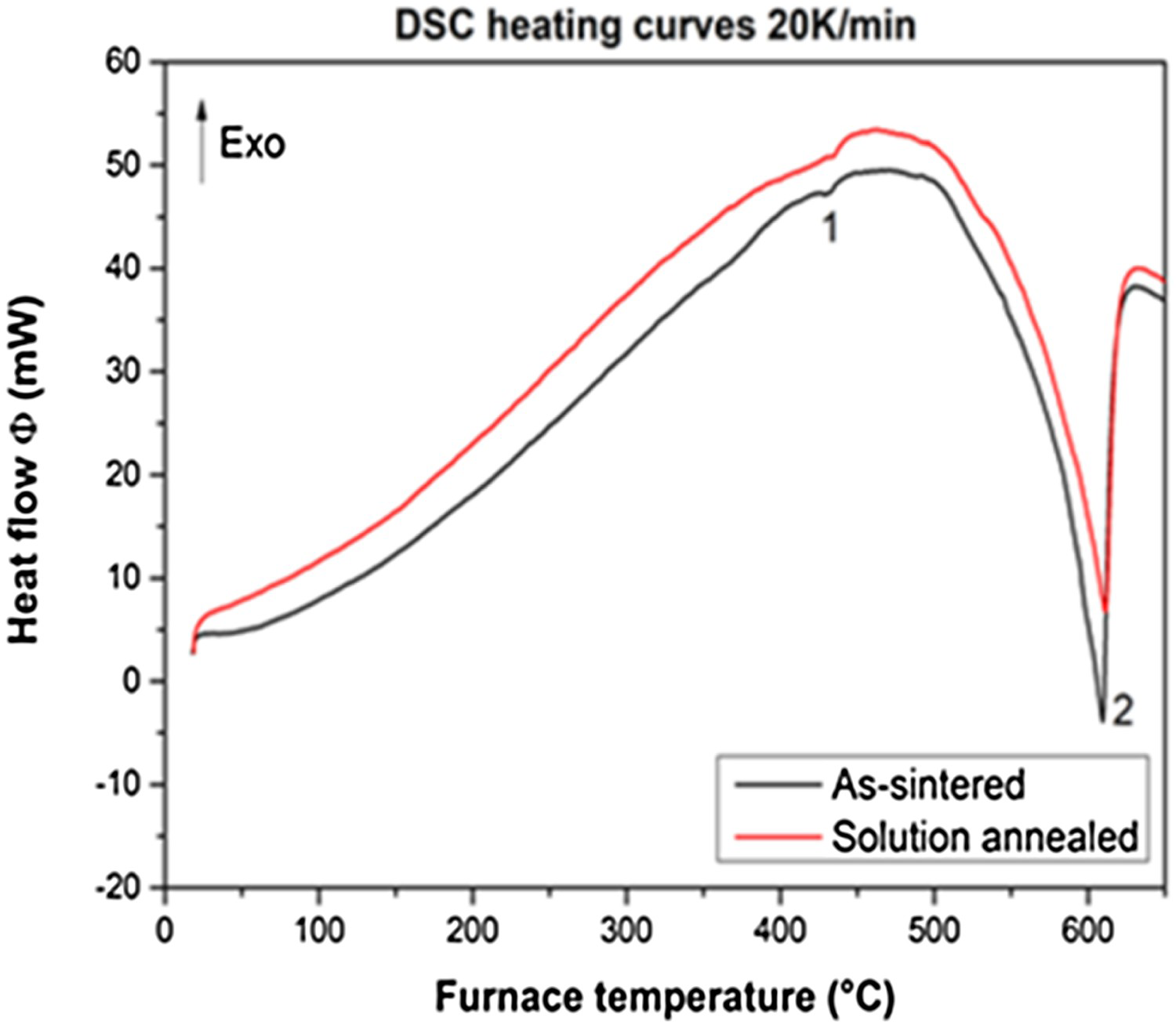
The optical micrographs of the as-sintered sample are shown in Figure 5. The overall microstructure consists of a continuous matrix with spherical particles and dark spots embedded in the matrix, as shown in Figure 5(a). The spherical particles are the sintered particles of AZ91. The dark borders are presumed to be Mg oxides (pointed out by arrows in the micrograph of Figure 5(b)) inherit from the feedstock powder. The black spots in the microstructures are identified to be pores. The total porosity of the as-sintered sample was calculated as 5 ± 2%. There is an increased pores concentration at boundaries between layers as shown in Figure 5(c), due to printing defects. The density of the material in the central part of the specimens was 98.8% Even if the sintering occurred in the semi-solid state, the large pores could not be closed.
Optical micrographs of the as sintered sample depicting (a) the overall matrix, (b) oxides around the sintered particles, some representative oxide layers are pointed by white arrows and (c) increased porosity at layer boundaries in the edge regions. Interfaces between adjacent layers are highlighted with dash lines.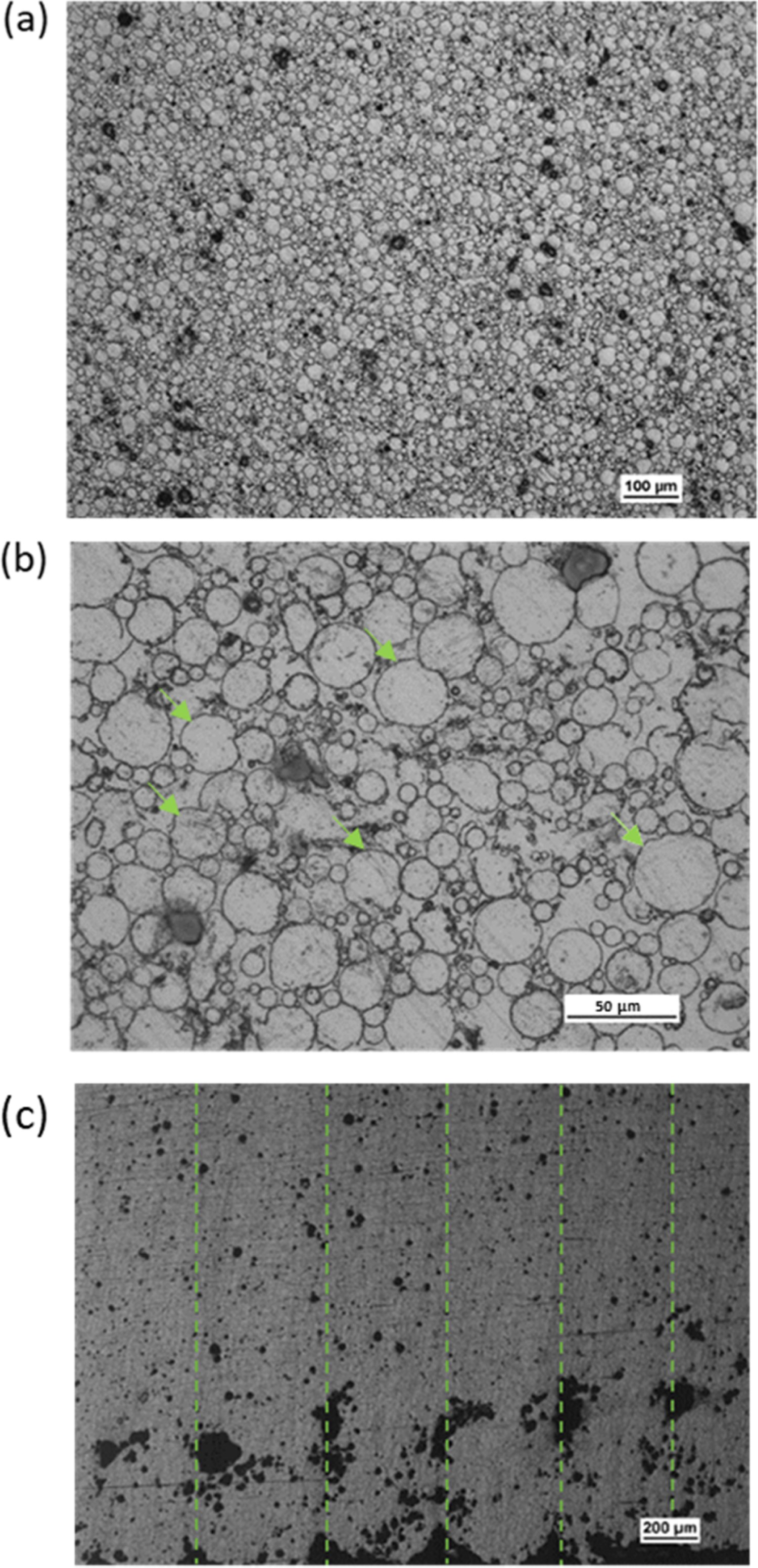
Figure 6(a,b) show the SEM microstructures of the as-sintered sample. The EDS results confirmed the presence of oxygen in the regions with bright contrast surrounding the sintered powder particles. Second phases that are rich in Al and Mn are noticeable within the matrix (see for instance the particle pointed out by the arrows in Figure 6(a)). They are supposed to be Al8Mn5 precipitates, in agreement with XRD results and with [22]. Furthermore, at higher magnifications, tiny white needles are visible, as shown in Figure 6 (b). These needles are consistent with the continuous precipitate morphology of Mg17Al12 which is illustrated in the study of Braszcznyska et al. [23] After solution treatment and aging at 168°C discontinuous precipitates are noticeable in the microstructure as illustrated in the micrograph of Figure 6(c). Braszcznyska et al [23] observed similar precipitates after aging at 150°C for 16 h in AZ91 produced by permanent mould casting.
SEM micrographs of the as sintered specimen at (a) low and (b) high magnification and (c) discontinuous precipitation after aging.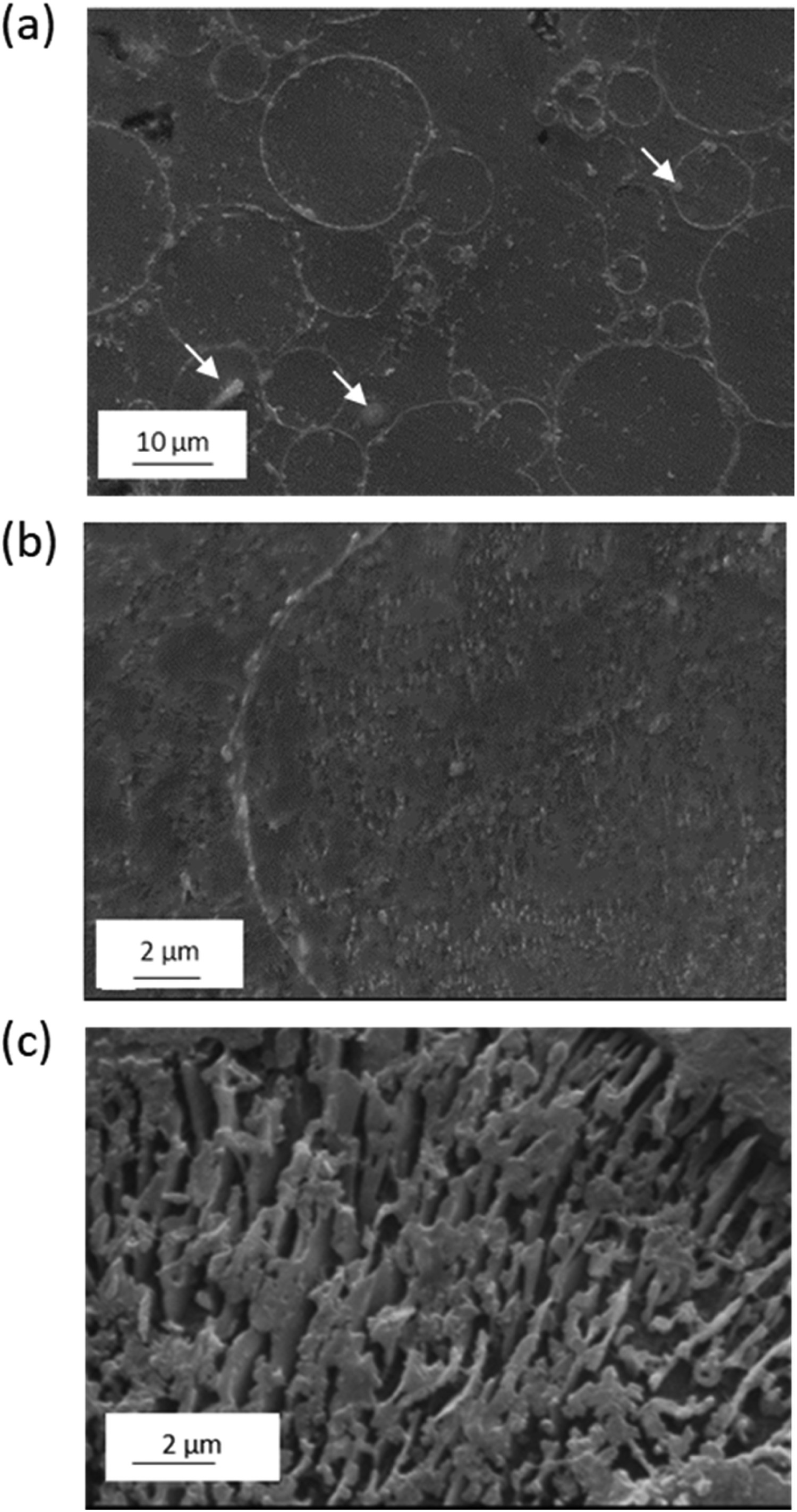
The Vickers hardness of the as-sintered, solution treated and aged alloys are summarised in Figure 7(a). The hardness of the as-sintered alloy slightly decreases after solution treatment. After the aging treatment, the alloy hardens due to precipitation of continuous Mg17Al12. The maximum hardness achieved is 81 HV. Hardness values of aged sample are consistent with those measured by Celotto et al. in cast AZ91E alloy aged at 150°C and 200°C [24].
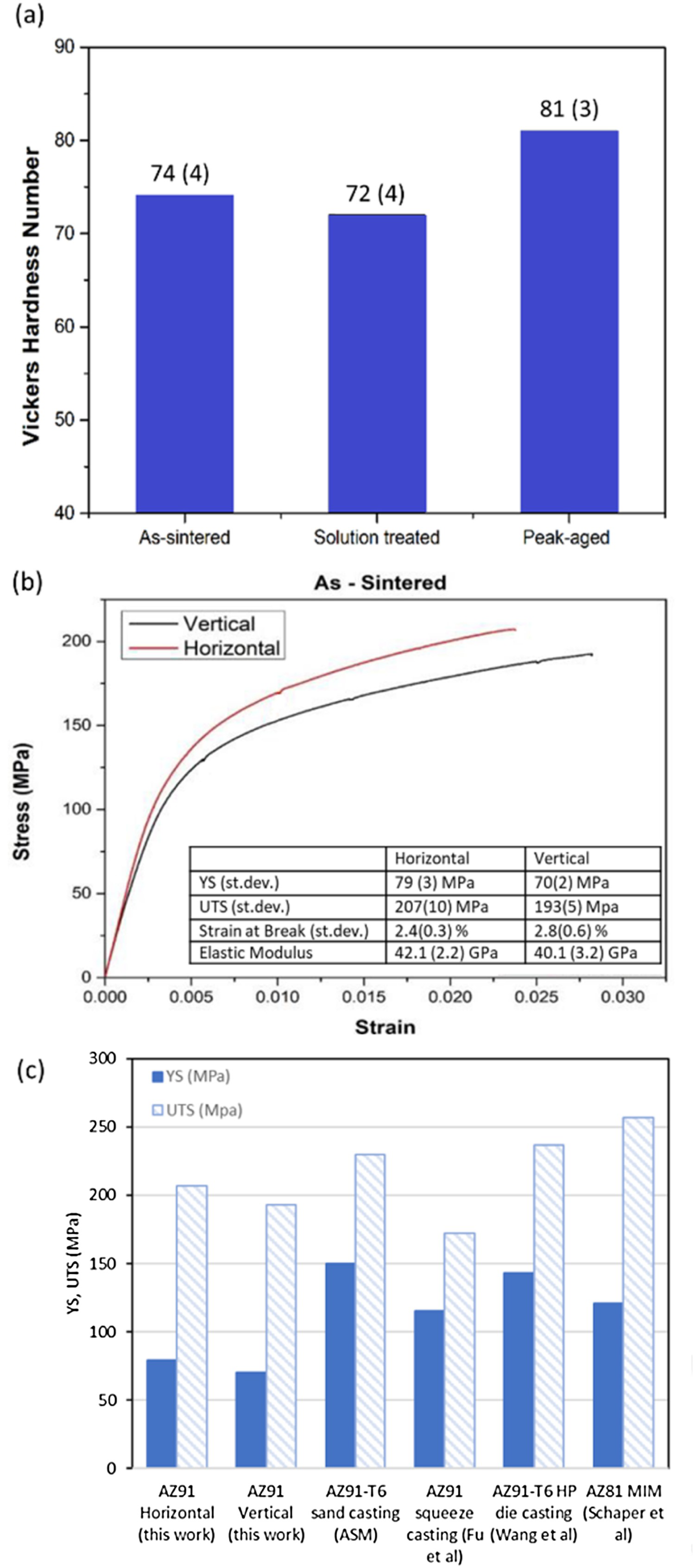
Tensile tests were performed on flat dogbone as-sintered specimens, representative curves are reported in Figure 7(b). The samples had a yield strength of 79 MPa in the horizontal build and 70 MPa in the vertical build. The ultimate tensile strength (UTS) was 207 MPa for the horizontal build and 193 MPa for the vertical build. The difference in strengths in build orientations is attributed to the different distribution of pores in the two samples, that are mainly concentrated at layer boundaries. Both samples show similar elongation at fracture, namely 2.4% and 2.8%, respectively. In a study conducted by Schaper et al, AZ81 based feedstock was used to prepare samples using MIM. In that case, the material showed YS of 121 MPa and UTS of 257 MPa in the as-sintered state [18]. In comparison, sand cast AZ91 has a yield strength of 150 MPa and a tensile strength of 230 MPa. A comparative illustration is depicted in Figure 7(c), in which literature results of AZ91 produced by squeeze casting and high pressure die casting are also reported [25–27]. The differences in strength among samples produced using different methods could be due mainly to the different porosity levels and size and distribution of second phases. Tensile tests were also conducted on the peak aged specimens, but the material showed a brittle behaviour and failed in the elastic regime, thus the results are not shown in this paper.
SEM micrograph of Figure 8 shows the fracture surface of the as-sintered AZ91 specimen. The crack has initiated on the surface of the dog bone specimen, close to the edge indicated by the arrow in the SEM image of Figure 8(a). The fracture propagated along the oxide layer boundaries, indeed spherical particles and ‘cups’ are well noticeable at higher magnifications. The cups are formed by the magnesium oxides after the spherical particles were displaced by the applied load. The SEM images in backscattered electron mode reveal large white polyhedrons rich in Al and Mn, therefore consistent with Al8Mn5 precipitates that broke in cleavage mode, suggesting that crack propagation has also taken place through such precipitates.
Fracture surfaces of as sintered sample at (a) 50×, (b) 500×, (c) BSE image at 5000× and (d) SE image at 5000×.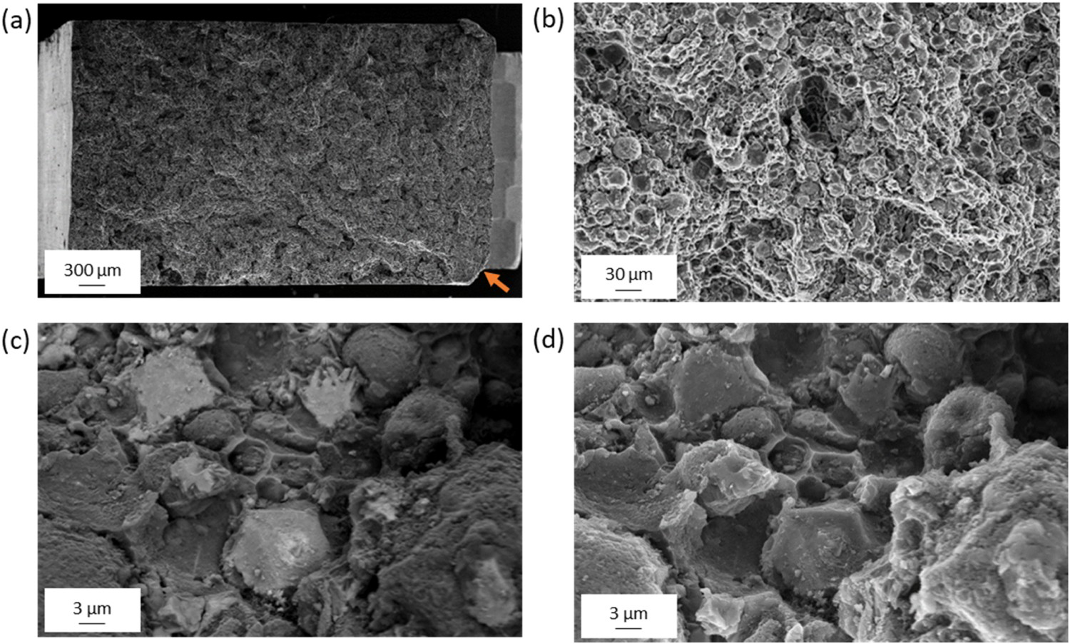
Conclusions
The AZ91 alloy was successfully produced using an EAM technique. The XRD diffractograms showed three sets of peaks in the as-sintered and the solution treated samples. These peaks were identified as α – Mg, Al8Mn5 and MgO. After T6 treatment, peaks of Mg17Al12 were also observed.
The alloy has a heterogeneous microstructure with a matrix α – Mg phase, Al8Mn5 and continuous precipitates of Mg17Al12 in the as-sintered and solution treated states. After the aging treatment, discontinuous precipitates of Mg17Al12 were observed.
The sintered samples exhibited a yield strength and UTS of 79 and 207 MPa, respectively, in the horizontal configuration and 70 and 193 MPa, respectively, in the vertical configuration.
Analysis of the fracture surface revealed that there is a continuous network of magnesium oxide layer around the powder particles. This acted as a preferential path for crack propagation.
Footnotes
Acknowledgements
The Helmholtz-Zentrum Geesthacht, where feedstock preparation, debinding and sintering was carried out by co-author J. Schaper, is highly acknowledged.The Italian Ministry of Education, University and Research is acknowledged for the support provided through the Project “Department of Excellence LIS4.0 - Lightweight and Smart Structures for Industry 4.0.”
Disclosure statement
No potential conflict of interest was reported by the author(s).