
Abstract
The clogging problem of close-coupled nozzles in the vacuum induction melting gas atomisation (VIGA) process is studied by numerical simulation and industrial experiments. To understand the factors affecting lick back on the nozzle, volume of fluid (VOF) multiphase flow model simulation was adopted to visualise the motion of alloy melt around the outer wall of the delivery tube in the primary atomisation process. When the melt orifice diameter is 4 mm and the atomisation pressure is close to 3.5 MPa, the atomisation process is continuous, the powder particle size is fine, and the atomiser can be reused. When the orifice diameter is 5 mm, and the atomisation pressure is greater than 2.5 MPa, the risk of nozzle clogging is avoided, the powder size is relatively coarse. In the case of using the same atomiser structure, this study explains the mechanism of lick-back and the resulting nozzle damage in VIGA units.
Introduction
In recent years, the demand for fine powders with narrow particle size distribution has increased due to the rapid development of thermal spray coating, additive manufacturing (AM) and metal injection moulding (MIM) applications [1–3]. Metal powder particles can be produced by various methods. One of the typical preparation processes is vacuum induction melting gas atomisation (VIGA), which uses close-coupled nozzles; electrode induction melting gas atomisation (EIGA), which can both prepare ultra clean metal powder. Owing to the advantages of large output, fine powder production and low gas consumption, VIGA technology is regarded to be one of the most important methods for powder production that is well-known in the literature [4–6]. Here, the metal melt flows out from the tip of the delivery-tube and immediately interacts with the high-pressure atomising gas. The kinetic energy of the gas is converted into the surface energy of the liquid metal, which is broken into a series of ligaments and small droplets. After a short period of cooling, the required spherical powder is obtained [7]. However, the most critical problem encountered in the VIGA process is nozzle blockage. When the supersonic gas interacts with the metal melt flow in the recirculation zone, some metal droplets will build up on the top plate of the gas nozzle and the outer wall of the delivery tube, resulting in nozzle damage by lick back. Limited studies have focused on this problem.
However, damage by lick back is unpredictable in the atomisation process. Once it happens, the atomisation stops, which brings huge economic loss and time waste to industrial production. Many parameters could affect these problems, such as melt viscosity, delivery tube geometry, atomiser geometry, atomiser & delivery tube coupling, atomisation pressure, etc. In previous studies, we studied the influence of the geometry [8], melt viscosity [9] and coupling length of the delivery tube [10] on the nozzle clogging. In the long-term industrial test, it is found that the change of atomisation pressure is one of the key factors leading to this problem. Many researchers have investigated various aspects of gas atomisation pressure parameters, Mates and Settles [11] reported that when the atomisation pressure reached 8.0 MPa, the gas atomisation intensity increased, and the finer powder could be obtained, but it would lead to higher gas consumption. Ting et al. [12] simulated the supersonic flow field structure of annular-slit nozzle. They reported that at lower pressures, the flow field presented an open-wake state. When the atomisation pressure was close to 4.82 MPa, the open-wake structure disappeared, and the closed-wake phenomenon appeared in the gas-flow field. Aydin et al. [13] further studied the effect of atomisation pressure on nozzle gas outlet velocity. The simulation and experimental results showed that the gas velocity did not increase monotonically with the increase of pressure. Arachhilage et al. [14] investigated the effect of gas pressure on the particle size distribution of metal droplets by VOF multiphase flow simulation method. This method realised the visualisation of the primary atomisation of metal melt flow. Zhao et al. [15] studied the effect of atomisation pressure on the gas flow field of close-coupled nozzle. The results showed that the gas velocity increases with the increase of gas pressure in a certain range. Wei et al. [16] proposed the method of combining VOF and discrete phase model (DPM) to predict the particle size distribution in secondary atomisation. Alloy steel powder prepared using high pressure has good fluidity and apparent density. The research of these scholars has accelerated the development of VIGA technology. This manuscript mainly studies the effect of the coupling between gas atomisation pressure and melt orifice diameter on nozzle clogging.
In this study, lick back during gas atomisation was investigated by analysing the coupling relationship between the different gas atomisation pressures (1.5, 2.5, 3.5 and 4.5 MPa) and melt orifice diameter (4.0 and 5.0 mm). Through the combination of numerical simulation [17] and industrial atomisation experiments, the behaviour of alloy melt in of alloy melt on close-coupled atomisation were understood. When the other parameters, such as the coupling length of the delivery tube, melt superheat and nozzle geometry are unchanged, the movement pattern of the alloy melt droplets around the outer wall of the delivery tube was observed. The numerical simulation results and the industrial test were compared. Gas atomisation was carried out with Ni-based alloy as raw material. While solving the problem of lick back, the particle size and morphology of the powder were optimised under different atomisation pressures and melt orifice diameters. This study not only provides a method to solve the problem of lick back, but also can improve the production efficiency of industrial atomisation.
Experimental setup and methods
Experimental setup
In this work, an atomisation device with a close-coupled nozzle system has been used to analyse the problem of nozzle blocking by the alloy melt in the process of atomisation. The improved VIGA equipment mainly consists of five parts: smelting system (Figure 1(a,b)) atomisation system (Figure 1(c)), gas supply system (Figure 1(d)), circulating water cooling system and vacuum system. The shape of powder collecting tank is shown in Figure 1(e). The height of the atomisation chamber is 4.2 m, and the diameter is 2 m. The load capacity of the magnesium oxide crucible is 20 kg. The feedstock material (here a Ni-based alloy) is melted in the crucible and heated by high-frequency induction furnace. The maximum heating temperature of the induction furnace is 2000 K, the heating power is 50–100 kW, and the vacuum degree of the equipment is 3.0 × 10⁻⁴ Pa. The temperature of alloy melt is measured by infrared laser thermometer. The heating rate of the alloy ingot is 50 K/min at the early stage and the heating rate was 75–90 K/min at the later stage. A gas flow meter (LZB-15) is installed on the gas pipeline to measure the gas flow rate. The measuring range is 1–20 m3/h. The overall structure diagram of the device is shown in Figure 1(f). The final powder morphology was observed by scanning electron microscope (LEO-150 SEM), and the particle size distribution was measured by a MICRO-PLVS laser particle sizer.
(a) Atomisation melting chamber (b) Atomising process of pouring Ni-based alloy (c) Close-coupled annular nozzle (d) Atomising argon cylinder (e) Powder collecting tank (f) Schematic of the vacuum induction melting gas atomisation process.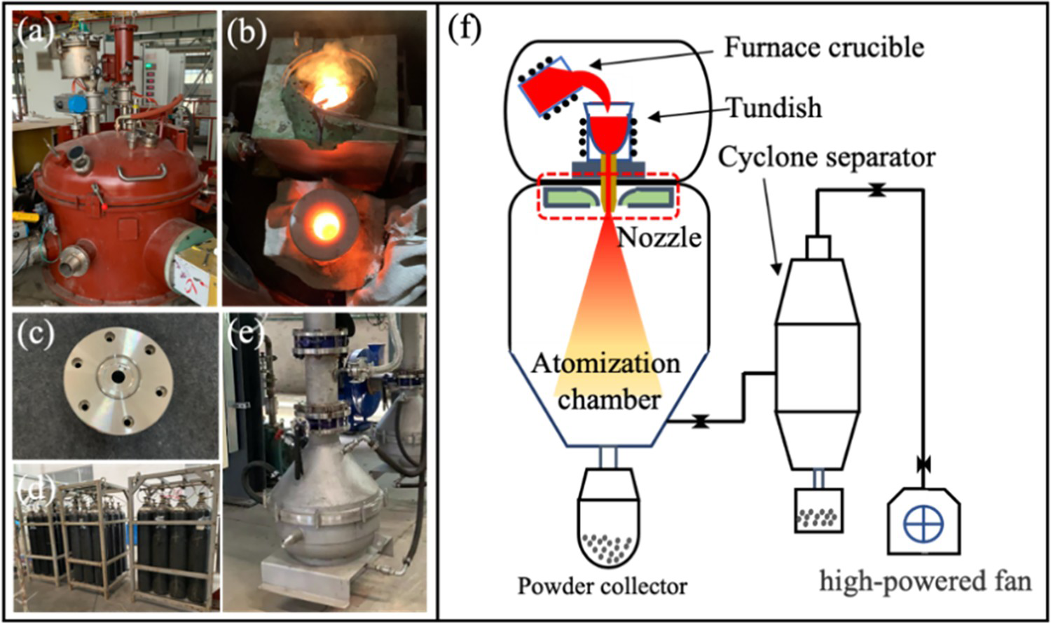
Figure 2(a) shows a schematic diagram of the closed-coupled nozzle considered in this study, referring to the nozzle structure of the traditional atomisation nozzle in the VIGA process and previously studied by researchers [18,19]. Two delivery tubes with different melt orifice diameters were used in these atomisation experiments: 4.0 mm, 5.0 mm, as shown in Figure 2(b). The minimum circumferential seam distance of de-Laval throat used in this test is 0.6 mm. In the atomisation process of the actual alloy melt, the atomising gas accelerates through the de-Laval nozzle to form a supersonic gas flow to atomize the melt flowing out of the delivery tube. The protrusion length of the melt delivery tube is 5 mm, the included angle of atomising gas injection is 55°, and argon is used as atomising gas.
(a) Schematic diagram of the close-coupled annular nozzle (b) Different melt orifice diameters of the delivery tube.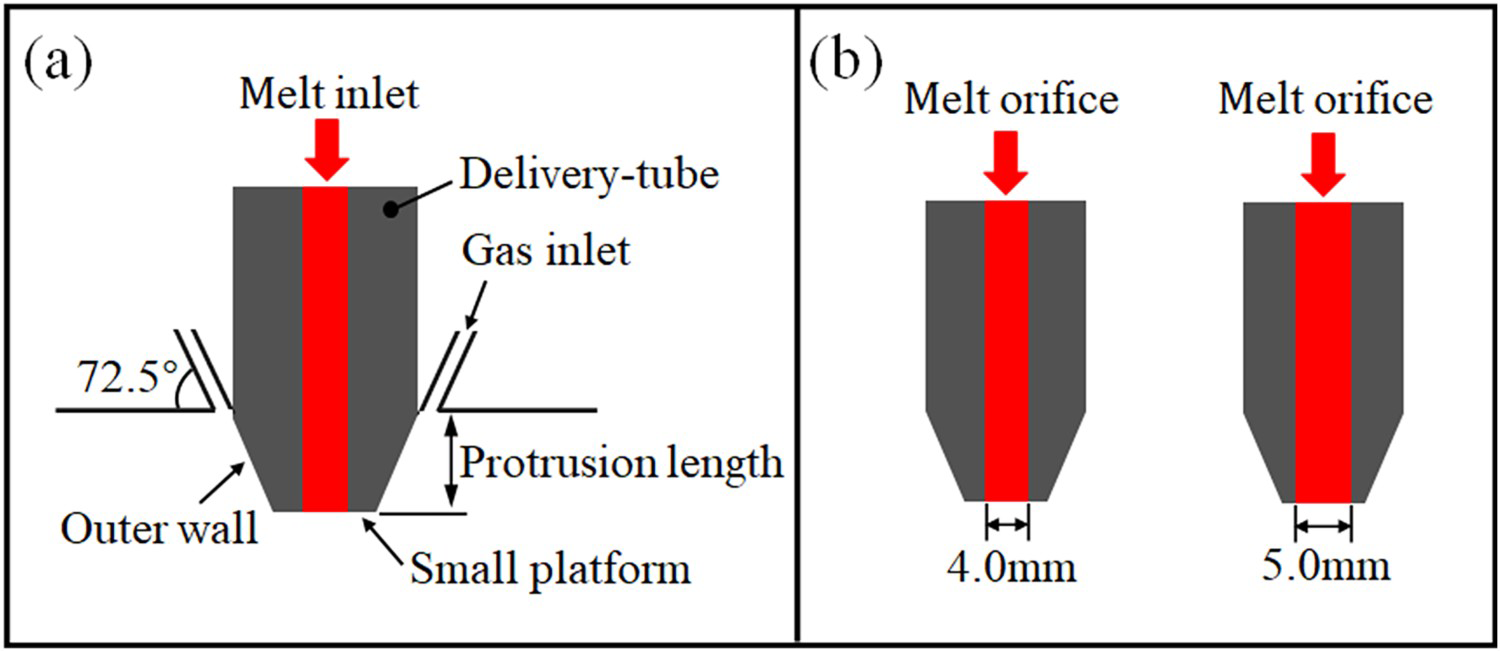
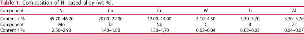
Composition of Ni-based alloy (wt-%).
Composition of Ni-based alloy (wt-%).
Experimental parameters in gas atomisation with different melt orifice diameters (MD).
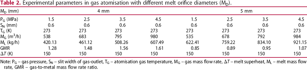
Note: PG – gas pressure, SN – slit width of gas-outlet, TG – atomisation gas temperature, MG – gas mass flow rate,  T – melt superheat, ML – melt mass flow rate, GMR – gas-to-metal mass flow rate ratio.
Before the industrial atomisation tests, in order to ensure that the alloy melt passing through the delivery tube flows out smoothly and will not stay in the tundish for too long time, the pressure at the tip of the delivery tube shall be tested, as shown in Figure 3(a). After the pressure gauge is fixed and sealed on the upper part of the delivery tube, the atomising gas (argon) is introduced into the nozzle. When the atomising gas is stable, the pressure value at the moment is read out from the pressure gauge. Figure 3(b) shows the variation curve of aspiration pressure and gas mass flow rate with atomisation pressure when the protrusion length of the delivery tube is 5 mm and the melt orifice diameter is 4 mm. As can be seen from Figure 3(b), when the inlet pressure increases, the aspiration pressure gradually decreases, the aspiration effect gradually increases, and the volume flow rate of gas increases. The numerical simulation results are consistent with the actual measured values and have the same trend. When the atomisation pressure is 4.5 MPa, the pressure value is close to −37 KPa.
(a) Gas aspiration pressure detecting device for the tip of delivery tube (b) Variation curves of aspiration pressure and gas volume flow rate under different atomisation pressures.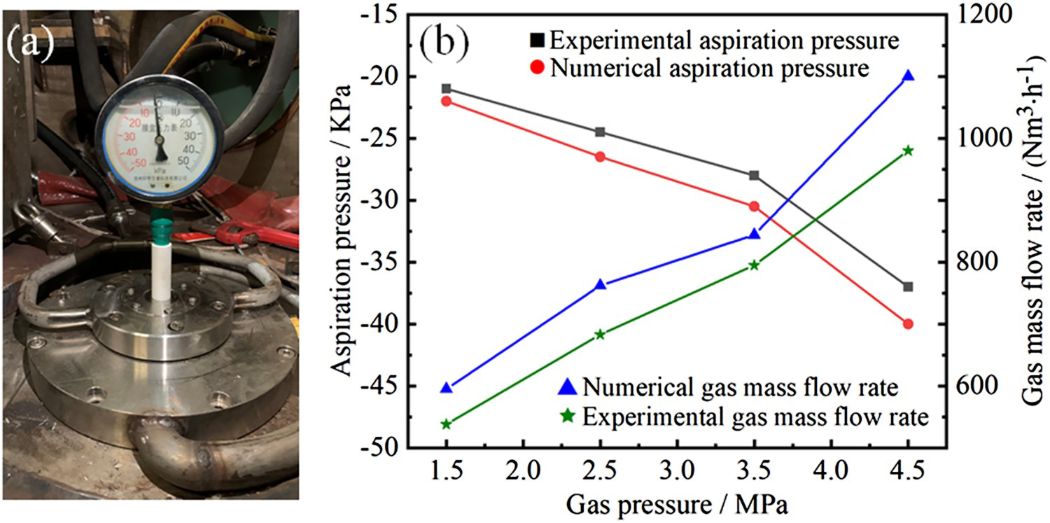
Boundary conditions and mesh
The gas-flow field of primary atomisation of alloy melt are numerically simulated by using the solver of Ansys Fluent 19.0. The atomising gas is set as a compressible ideal gas, and the calculation of flow field is carried out under steady-state condition. The length of the calculation area is 154 mm, and the maximum width is 50 mm. To reduce the amount of calculation and time of simulation, the geometric model of atomisation area is two-dimensional axisymmetric. The alloy melt inlet is set as the velocity-inlet, the melt movement is 2 m/s, and the atomising gas inlet is set as the pressure-inlet. The physical parameters of alloy melt [17] and atomising gas are shown in Table 3. The boundary conditions of the atomisation area are velocity-inlet, pressure-inlet, pressure-outlet, and no-slip wall, as given in Figure 4(a). The surface tension coefficient between the alloy melt and argon is set to 1.84 N/m. The specific simulated boundary conditions are shown in Table 4.
(a) Computational domain and boundary conditions (b) Mesh used in close-coupled nozzle simulation. Physical parameters of Ni-based alloy and argon [17]. Initial boundary conditions for simulation.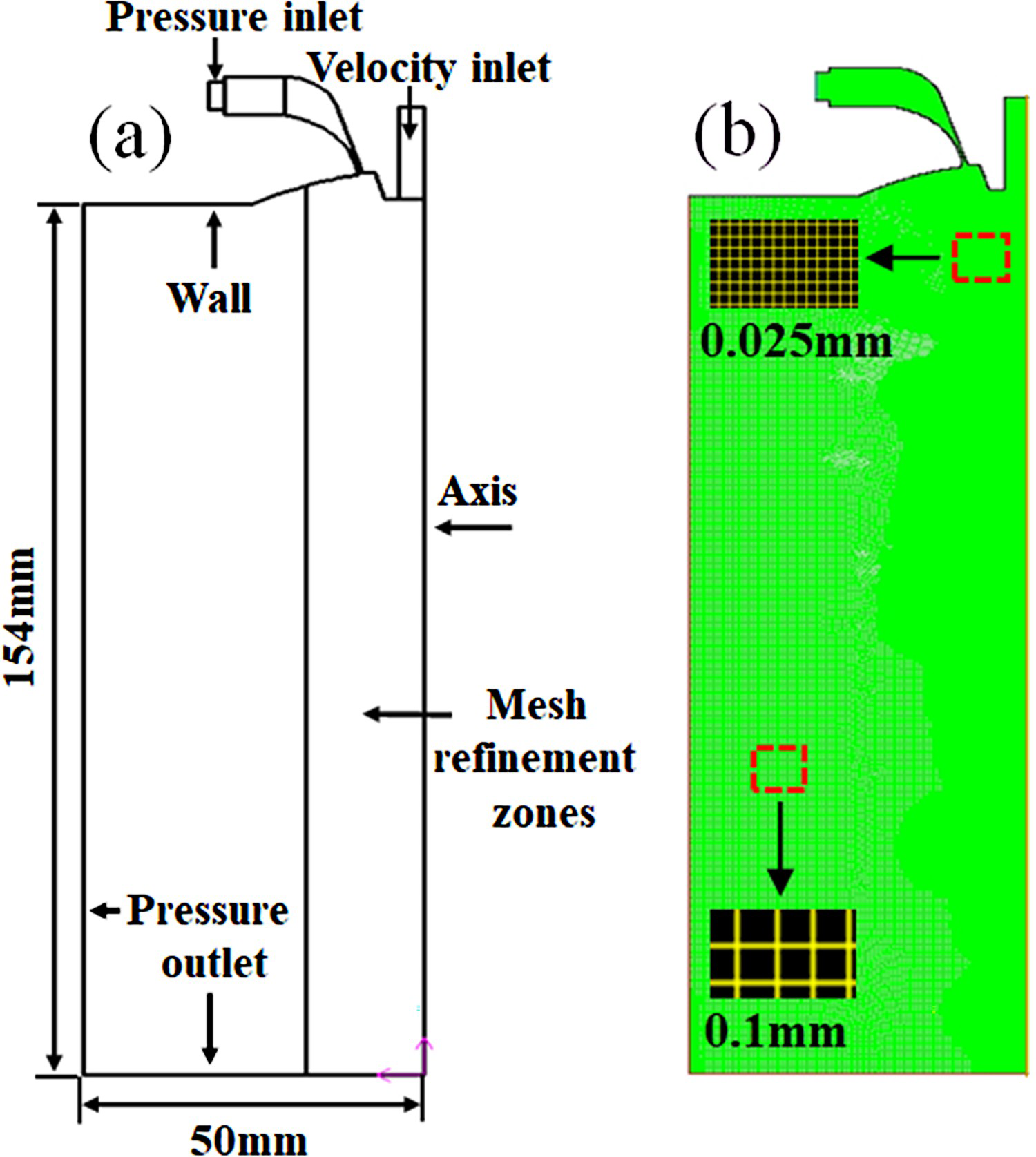
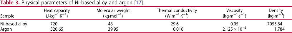
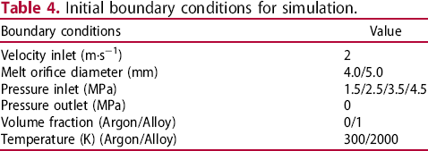
Figure 4(b) shows that the geometric model is meshed with GAMBIT software and the mesh size is set through the size function. In the primary atomisation area, in order to capture finer alloy melt droplets, the dynamic mesh adaptive method is used to refine the boundary and the areas with large pressure changes, such as the gas-flow field at the nozzle outlet and the tip of the delivery tube, so as to meet the accuracy requirements of the primary atomisation simulation. The minimum mesh size is 0.025 mm and the total number of elements is 517300. This method can improve the visualisation quality of the melt atomisation process. The numerical simulation method is based on the SIMPLEC pressure-velocity coupling algorithm, and the pressure interpolation scheme is applied to PRESTO. The iteration time step is 10−7s, and 100,000 steps are needed to ensure the stable convergence of the flow field. The transient solver of the implicit second-order upwind discrete scheme is used to solve the partial differential equations such as momentum and energy.
Before the primary atomisation simulation of two-phase flow, it is necessary to calculate the single-phase gas (argon) flow field. The velocity-inlet is set as the wall and the k-ϵ turbulence model is applied to simulate the supersonic compressible gas-flow field at the outlet of the nozzle. The k- model is suitable for complex flows such as high Reynolds number, mixed flow and swirl. The governing equations of single-phase gas flow field simulation include a continuous equation, momentum equation and energy equation, as follows [20]:
Continuous equation:
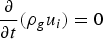
 is the gas density,
  is the velocity component in direction
  , and t represents the time.
Momentum equation:
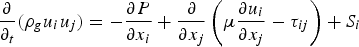
 is the velocity component in direction
  , P is the pressure,
  is the dynamic viscosity,
  is Reynold's stress tensor, and
  represents the generalised original term of the momentum equation.
Energy equation:
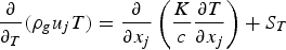
 represents the viscous dissipation term.
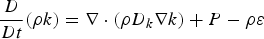
The k- model contains k and
  equations, which are as follows [21]:
 equation:
 equation:
 is the turbulent kinetic energy;
  represents the density;
  is the Effective diffusivity for
  ;
;  is the turbulent kinetic energy production rate;
  represents the turbulence special dissipation;
  represents the Effective diffusivity for
  ;
;  and
and  represent the model coefficient;
  is the velocity.
Once the calculation of single-phase gas flow field is stable, the gas–liquid two-phase flow is simulated. Set the alloy melt to enter the delivery tube through the velocity-inlet. The volume of fluid (VOF) model and k- model (Equations (4) and (5)) is combined to simulate the breakup process of the alloy melt during the primary atomisation process. This simulation mainly described the interactions between the metal flow and gas, the exchange of energy [19], and the formation of droplets. Only physical changes were modelled in these processes; hence, the relevant basic, physical equations, such as the continuity (Equation (6)) and momentum equations (Equation (7)), are listed below [22].


Continuous surface force (CSF) method [14] is used to model the surface tension force (body force), which only has non-zero values at the interface between gas and alloy melt. The surface tension force is defined as [24]:

 is the local interface curvature,
  is the surface tension coefficient and
  represents the interface normal.
After the meshes of the gas-flow field and the tip of the delivery tube are encrypted, in order to display more small droplets, large eddy simulation (LES) model is used instead of k- model to simulate the primary atomisation process of alloy melt. Compared with other models, the LES model can filter out turbulence and divide it into large and small eddies. Yoshizawa et al. [25] and Menon et al. [26] proposed a sub-grid kinetic energy model. The transport equation for this model is as follows:
 is the sub-grid kinetic energy,
  is the sub-grid stress,
  is the sub-grid viscosity coefficient,
  is the turbulent energy dissipation rate, and
  is the velocity.
Mechanism analysis of the nozzle clogging behaviour
At present, the atomiser often used in the VIGA process is a close-coupled type [2]. The factors leading to nozzle clogging are complex, the occurrence time is very short, and its formation process is difficult to observe in production. Figure 5 shows the mechanism of nozzle clogging. It can be seen from Figure 5(a) that when nozzle clogging occurs, some alloy melt often solidifies in two different positions: gas-outlet of the nozzle and outer wall of the delivery tube. After the primary atomisation of the alloy melt under the delivery tube, some ligaments and droplets reflow upward along the outer wall of the delivery tube and solidify on the wall in the low-temperature atomising gas environment. The alloy melt droplets far away from the edge of the delivery tube will be adsorbed near the gas-outlet of the nozzle and finally bonded to the upper cover of the nozzle. Figure 5(b) shows the nozzle clogging phenomenon in the industrial atomisation test. The solidified alloy melt on the outer wall of the delivery tube will not only damage the nozzle but also cause the termination of atomisation, this will bring serious consequences to the continuity of atomisation process and powder quality.
Mechanism of nozzle clogging during alloy melt atomisation (a) Schematic diagram of alloy melt droplet aggregation in the close-coupled nozzle (b) Photograph of nozzle clogging after atomisation.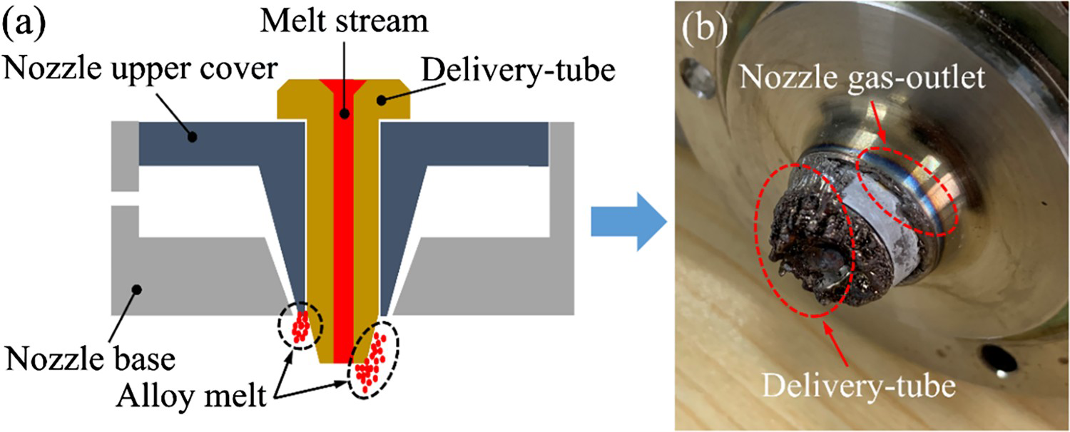
Figure 6 shows the state of the delivery tube and nozzle during the industrial test under different atomisation pressures with the melt orifice diameter of 4 and 5 mm, respectively. In these images, the white circle marks that the alloy melt is cooled and solidified on the gas-outlet of the nozzle, which will cause irreversible damage to the nozzle. The green circle indicates that the alloy melt is bonded to the outer wall of the delivery tube. The red circle refers to the solidification of the alloy melt on the small platform of the delivery tube. The melt orifice diameter of the delivery tube used in Figure 6(a1)–(a4) is 4 mm. From Figure 6(a1), it can be found that when the atomisation pressure is 1.5 MPa, the alloy melt gradually accumulates at the outer wall of the delivery tube and the gas-outlet of the nozzle during the atomisation process. This not only interferes with the gas-flow field structure on the side of the delivery tube, but also hinders the smooth outflow of alloy melt from the delivery tube for atomisation. For 2.5 MPa, as shown in Figure 6(a2), the melt flow gradually solidified and accumulated on the small platform of the delivery tube, and finally clogged the tube completely. However, when the atomisation pressure is 3.5 MPa, the atomisation process is continuous, and no residual alloy melt is found on the gas-outlet of the nozzle and the outer wall of the delivery tube, as given in Figure 6(a3). As the atomisation pressure increases to 4.5 MPa, it can be found that the alloy melt appears on the inner wall and tip of the delivery tube, as shown in Figure 6(a4). When the melt orifice diameter is 5 mm, as shown in Figure 6(b1)–(b4), the nozzle clogging problem only occurs when the atomisation pressure is 1.5 MPa (Figure 6(b1)), and the solidification position of the alloy melt is similar to Figure 6(a1). When the atomisation pressure is 2.5–4.5 MPa, the atomisation process is continuous without nozzle clogging.
Appearance of melt delivery tube and nozzle under different atomisation pressures after industrial test (a) melt orifice diameter of 4 mm (b) melt orifice diameter of 5 mm.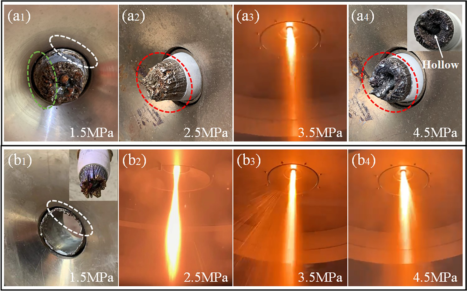
Figure 7 shows images of the primary atomisation of the alloy melt in the recirculation zone numerically simulated by LES (Large Eddy Simulation) model, which can visualise the surface of breakup of the alloy melt. Table 5 shows the simulation time of primary atomisation of alloy melt under different atomisation pressures. Due to a large number of turbulent eddies near the recirculation zone below the delivery tube, the alloy melt film will be broken into many ligaments and small droplets by strong atomising gas. The inconsistent direction of turbulent eddies makes the alloy melt droplets disperse near the tip of the delivery tube [14]. Firstly, the atomisation state of the alloy melt is observed when the melt orifice diameter is 4 mm. For 1.5 MPa, as shown in Figure 7(a1), In the process of atomisation, supersonic gas continuously scours the sidewall of the delivery tube, and the surface temperature is low. After primary atomisation, small droplets of alloy melt collide with the surface, and will quickly cool and bond in a lower atomised gas environment. it can be intuitively observed that the alloy melt through the primary atomisation is contacted with the small platform and outer wall of the delivery tube, respectively. under the action of gas-flow, and some melt droplets move to the gas-outlet of the nozzle and bond to the upper cover of the nozzle. Figure 7(a2) indicates that when the atomisation pressure is 2.5 MPa, part of the alloy melt after primary atomisation collides with the end of the delivery tube, and the collision time is extreme. The droplet cooling rate of the larger alloy melt is slow and will move downward with the gas, while the droplet cooling rate of the smaller alloy melt is faster. When the temperature of the alloy melt is lower than the melting point, it will bond to the small platform at the end of the delivery tube. However, when the atomisation pressure is 3.5 MPa, no bonded alloy melt is found on the wall of the delivery tube, and the alloy droplets after the primary atomisation immediately move downward with the supersonic gas-flow, as presented in Figure 7(a3). When the atomisation pressure is 4.5 MPa, from Figure 7(a4), it is found that the alloy melt appears again on the small platform of the delivery tube. However, when the melt diameter is 5 mm, it is found from Figure 7(b1)–(b4) that the liquid film of the alloy melt becomes thicker during the primary atomisation, and the ligament after the melt is broken increases. Only when the atomisation pressure is 1.5 MPa, the alloy melt freezes on the outer wall of the delivery tube and the gas-outlet of the nozzle, as shown in Figure 7(b1). This is consistent with the results obtained from the actual industrial test, and also proves the accuracy of the numerical simulation.
Primary atomisation cloud diagram of alloy melt under different atomisation pressures (a) melt orifice diameter of 4 mm (b) melt orifice diameter of 5 mm. The simulation time of primary atomisation of alloy melt under different atomisation pressures.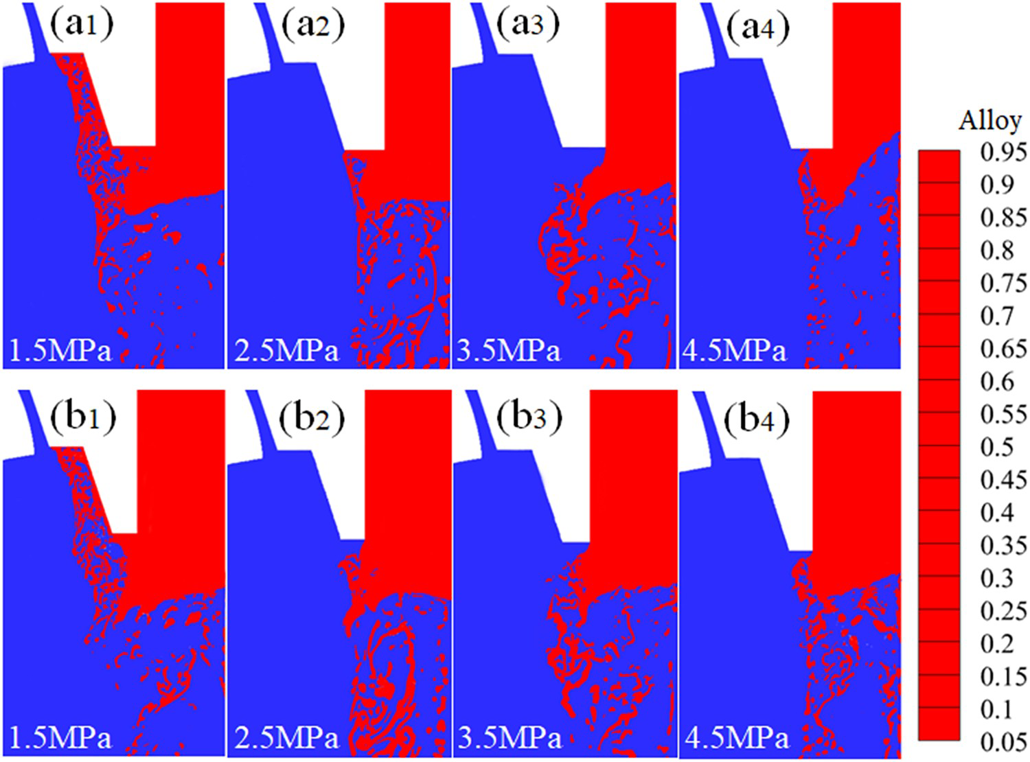
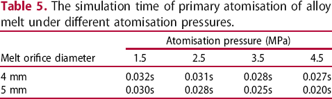
Figure 8 shows the temperature distribution in different areas at the end of the delivery tube. Based on the data in Table 6, it is found that the alloy melt temperature in the delivery tube is 1999K, as shown in point A. The temperature of the small platform at the end of the delivery tube is higher than that of the side wall of the delivery tube, which are 1850 and 1620 K respectively. The temperature of the alloy melt bonded on the side wall of the delivery tube is less than 1550 K, which indicates that the alloy melt begins to solidify gradually in the cold atomised gas environment, such as point D. Point E represents the alloy melt ligament after primary atomisation, at a temperature of 1870K, which is then further broken by secondary atomisation through interaction with supersonic gas.
(a) The distribution of alloy melt at the end of the delivery tube during the primary atomisation process. (b) The temperature distribution graph at the end of the delivery tube. Temperature in different areas at the end of the delivery tube.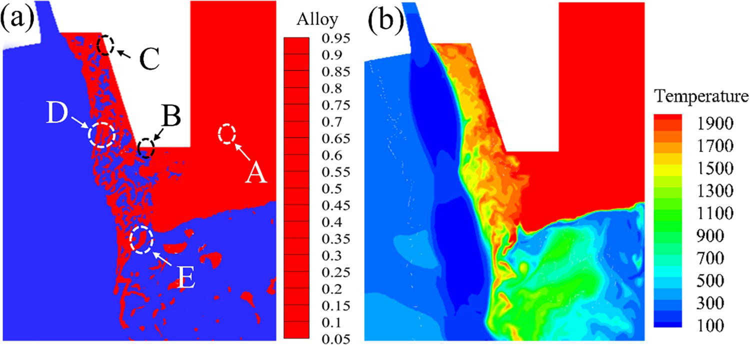
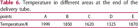
The above numerical simulation results show that when the melt orifice diameter is 4 mm, the nozzle clogging disappears gradually with the increase of atomisation pressure. However, when the atomisation pressure is 4.5 MPa, the alloy melt is accumulated at the tip of the delivery tube after the industrial test. In this case, we simulated and calculated the gas-flow field at 1.5, 2.5, 3.5 and 4.5 MPa, respectively, as given in Figure 9. It can be seen from Figure 8 that during the atomisation process of the close-coupled nozzle, there is a recirculation zone under the delivery tube [7]. When the atomisation pressure is within the range of 1.5–3.5 MPa (Figure 9(a)), the distance between the upper part of the recirculation zone and the small platform of the delivery tube is almost the same. However, when the atomisation pressure increases to 4.5 MPa, the position of the recirculation zone is relatively upward, and part of the recirculation zone enters the delivery tube. The velocity of upward gas in the recirculation zone reaches about 185 m/s, and the axis velocity stagnation point (point C) is closest to the delivery-tube, as shown in Figure 10, which makes the melt flow of the alloy begin to atomisation without leaving the tip of the delivery tube. Under the action of the ‘umbrella structure’ principle [15], the melt flow edge gradually solidified from the inside to the outside of the small platform. In severe cases, the delivery tube will be completely blocked similar to Figure 6(a4). In addition, the strong gas-flow in the recirculation zone will reverse spray in the melt delivery tube, which will reduce the downward flow velocity of the alloy melt, and further increase the heat dissipation of the melt before atomisation, resulting in the early solidification of the melt without leaving the delivery tube. Compared with the 4 mm diameter, when the melt orifice diameter is 5 mm, as shown in Figure 9, the distance between the atomisation recirculation zone and the small platform of the delivery tube increases, and the position of the recirculation zone moves down within the atomisation pressure of 3.5–4.5 MPa, as shown in points A (4.5 MPa) and B (3.5 MPa) in Figure 10, so that the alloy melt carries out primary atomisation at a relatively far position below the delivery tube, avoiding the risk of nozzle clogging.
Velocity nephogram of gas-flow field under different atomisation pressures (a) melt orifice diameter of 4 mm and (b) melt orifice diameter of 5 mm. Axial velocity comparison curve of gas-flow field.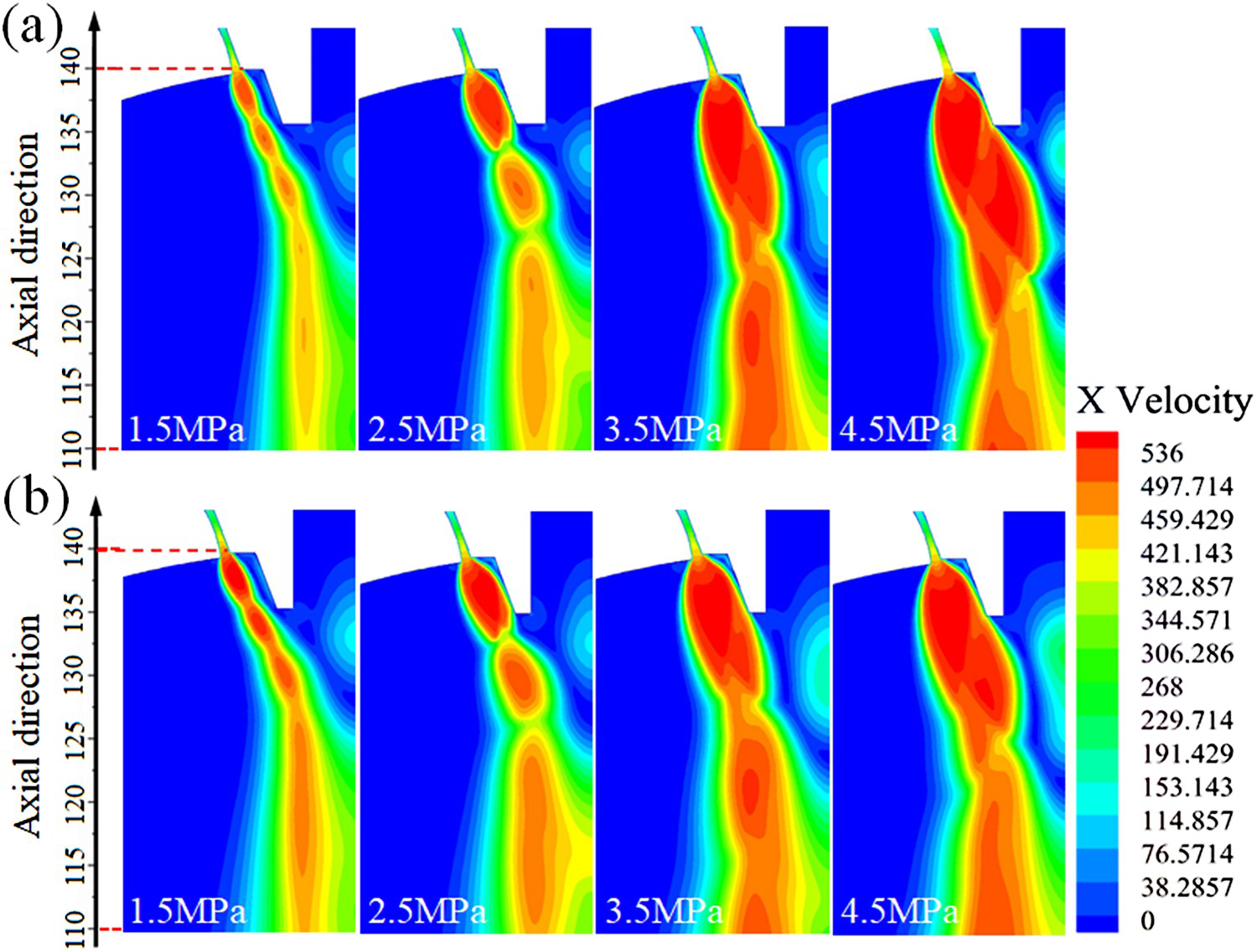
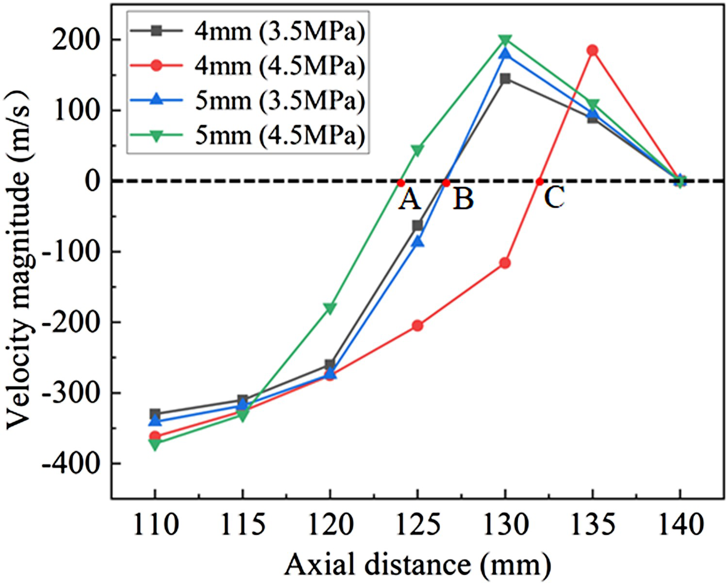
According to the observation of the structural morphology of the nozzle and delivery tube after atomisation in the industrial test (Figure 6), the atomisation pressure and velocity vector nephogram mainly discussed here correspond to the melt orifice diameter of 4 mm. Figure 11(a) shows the pressure contour nephogram near the close-coupled nozzle under different atomisation pressures. When the atomisation pressure is 1.5 MPa, the supersonic gas expands completely near the outer wall of the nozzle, and the area marked by the red circle is a negative pressure area. After the primary atomisation, the droplets of the alloy melt will be sucked back to the negative pressure area. In the cold atomising gas environment, the alloy melt on the outer wall of the delivery tube and the upper cover of the nozzle is solidified. This will change the external structure and morphology of nozzle outlet and delivery tube and seriously affect the stability of the atomisation process. However, when the atomisation pressure is 2.5–4.5 MPa, the expansion shock wave of supersonic gas is completely attached to the outer wall of the delivery tube. The graph shows that the negative pressure zone is replaced by the positive pressure zone, and the droplets of the alloy melt are hardly sucked into the upper cover of the nozzle during the atomisation process, so that the repeated use of the nozzle can be guaranteed.
(a) The pressure contour nephogram near the close-coupled nozzle under different atomisation pressures with melt orifice diameter of 4 mm (b) Velocity vector fields around the delivery tube under different atomisation pressures with melt orifice diameter of 4 mm.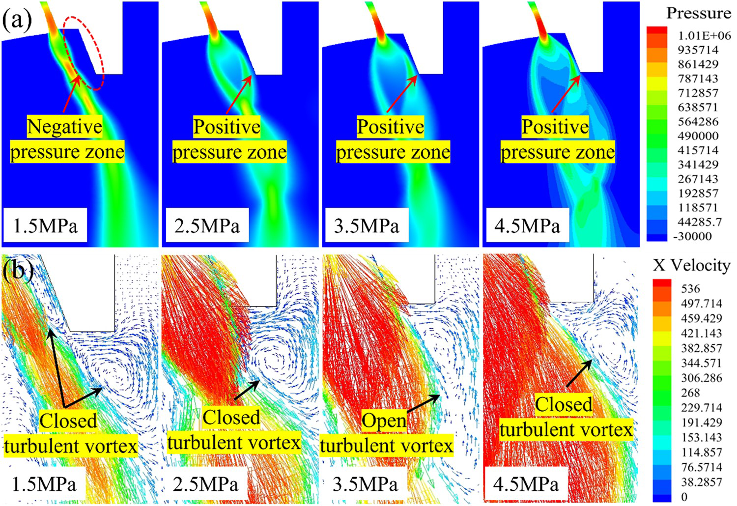
For better observation of back flow mechanism at the negative pressure area and the alloy melt hanging flow phenomenon at the small platform of the delivery tube, Figure 11(b) presents the velocity vector fields around the delivery tube under different atomisation pressures. For 1.5 MPa, the alloy melt droplets after primary atomisation are first involved in the closed turbulent vortex below the delivery tube. A small number of droplets will be sucked into the turbulent vortex (negative pressure zone) on the outer wall of the delivery tube. This will burn the upper cover of the nozzle and clog the melt delivery tube, halting the atomisation process, which is consistent with the results reported by Motaman et al. [27]. When the atomisation pressure is 2.5 MPa, it can be found that only a closed turbulent vortex exists below the small platform of the delivery tube, so that the long-time reflux melt droplets solidified on the small platform and eventually blocked the delivery tube. However, for 3.5 MPa, an open turbulent vortex appears below the small platform of the delivery tube. The alloy melt droplets quickly move downward with the gas-flow in the turbulent vortex and hardly touch the small platform. When the atomisation pressure increases to 4.5 MPa, the supersonic gas-flow at the outlet continues to expand, resulting in the turbulent vortex at the end of the delivery tube changing from open vortex to closed vortex, which will increase the risk of melt droplets solidifying on the small platform of the delivery tube, and the problem shown in Figure 6(a4) appears.
In addition, when the melt orifice diameter is 4 mm, we monitored the pressure change of the atomisation tower during the experiment process, as shown in Figure 12. It can be found that when the atomisation pressure is 1.5–3.5 MPa, the internal pressure of the atomisation tower is negative pressure, about: −28–4 KPa, which can promote the alloy melt to flow out smoothly from the delivery tube. However, when the atomisation pressure is 4.5 MPa, the pressure of the atomisation tower is positive pressure, about 1 –14 KPa. This will hinder the downward flow of the alloy melt and cause back injection in serious cases. This can also explain the test situation in Figure 6(d) at 4.5 MPa.
Pressure detection range of atomisation tower in industrial atomisation test.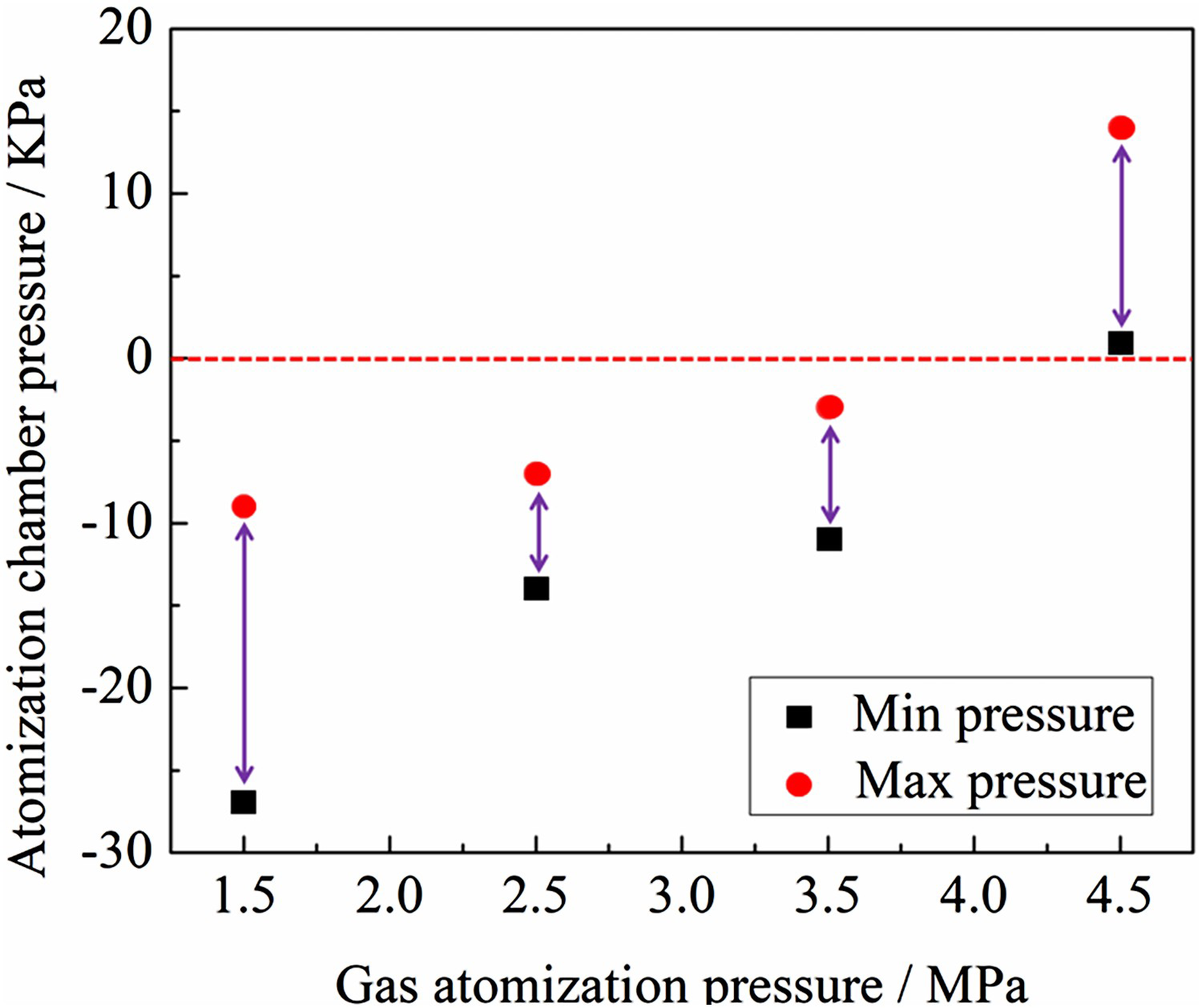
Statistics of atomisation time of each experiment under the different gas pressures.
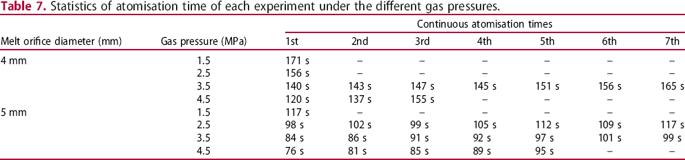
Comparing the simulation and experimental results, it is found that continuous atomisation can be achieved at 3.5 and 4.5 MPa. Therefore, this section only enumerates the SEM images of different melt orifice diameters (4 and 5 mm) powders prepared under the atomisation pressure of 3.5 and 4.5 MPa as shown in Figure 13 (since to the alloy melt solidifies at the gas outlet of the upper cover of the nozzle under the atomisation pressure of 1.5–2.5 MPa, the spray tray is damaged and cannot be reused, so it is not considered). When the melt orifice diameter is 4 mm, as shown in Figure 13(a,b), the Ni-based alloy powder has fine particle size, good sphericity, and smooth surface. However, when the melt orifice diameter is 5 mm, the powder particle size increases, which is caused by the smaller GMR (gas-to-metal mass flow rate ratio) due to the larger melt mass flow rate, as shown in Figure 13(c,d).
SEM images of powder with different melt orifice diameters and atomisation pressures (a) 4 mm, 3.5 MPa (b) 4 mm, 4.5 MPa (c) 5 mm, 3.5 MPa (d) 5 mm, 4.5 MPa.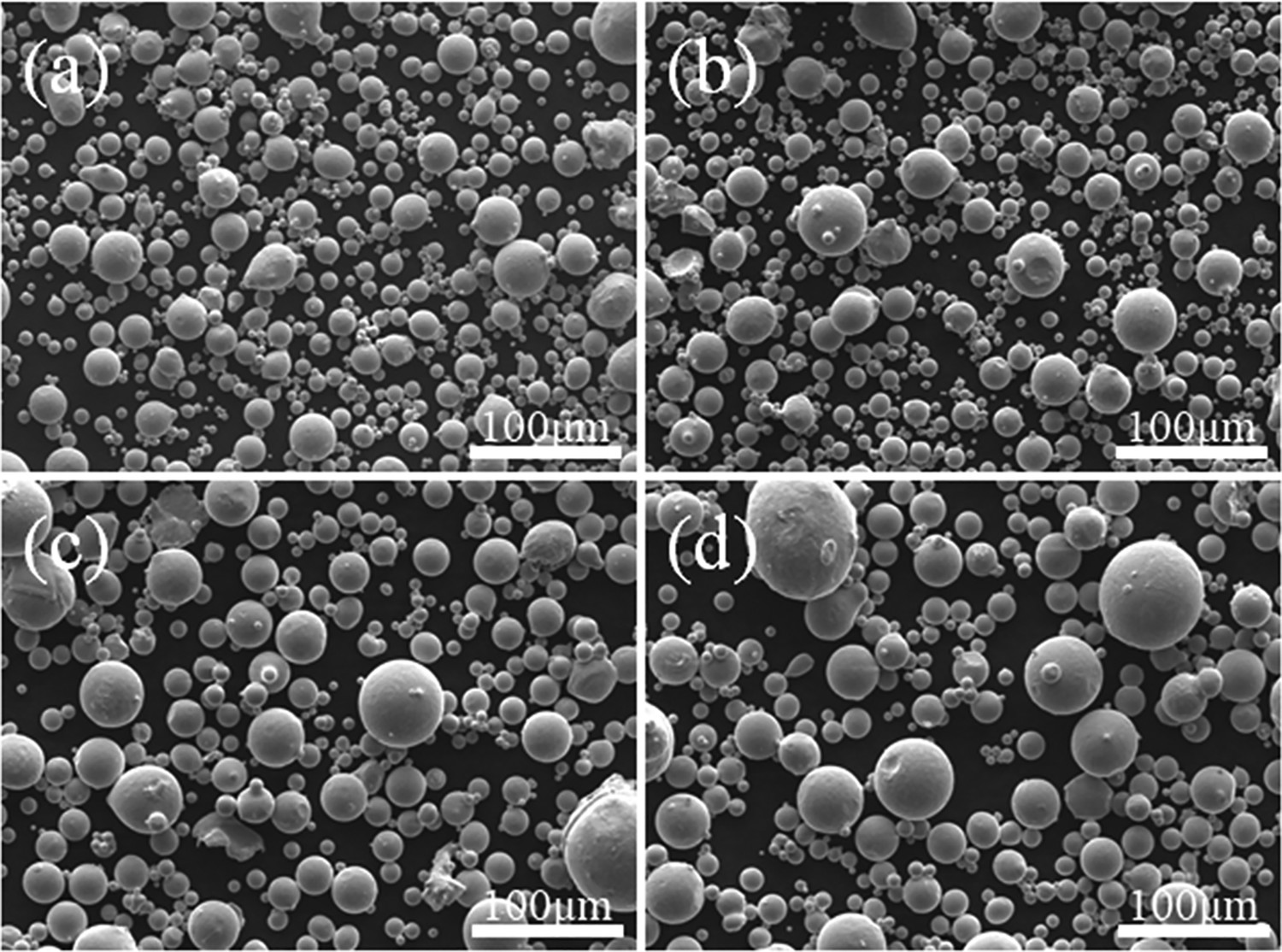
The particle size distribution of atomised powder with different melt orifice diameters was measured under the pressure of 3.5 and 4.5 MPa, respectively. As shown in Figure 14(a), when the melt orifice diameter is 4 mm and the atomisation pressure is 3.5 MPa, the median diameter of the particles is about 41.02 μm. When the atomisation pressure is 4.5 MPa, the median diameter of particles is about 36.59 μm. However, when the melt orifice diameter is 5 mm, although the atomisation pressure is different (3.5 and 4.5 MPa), the median diameter of the powder is relatively close, about 51 μm, as shown in Figure 14(b).
Comparison of the particle size distributions of the powder produced under atomisation pressure of 3.5 and 4.5 MPa (a) melt orifice diameter of 4 mm (b) melt orifice diameter of 5 mm.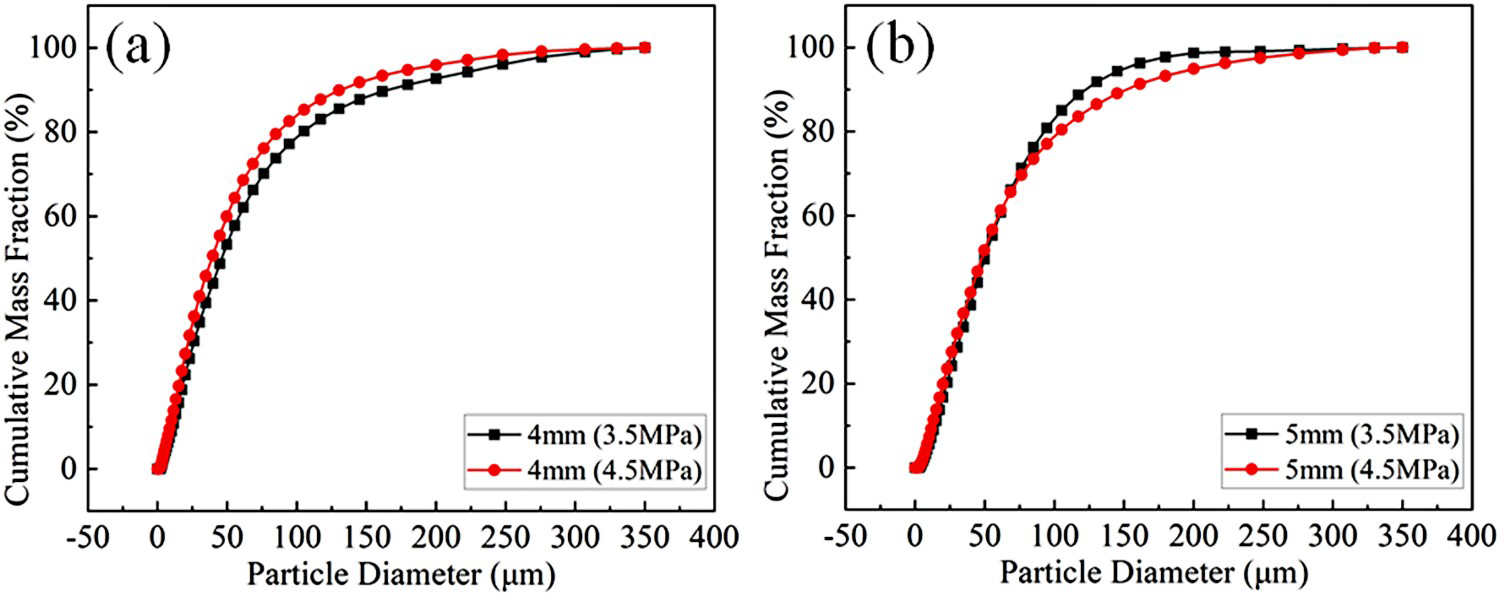
In the VIGA technology, in order to solve the frequent clogging problem of close-coupled nozzles, the coupling relationship between atomisation pressure and melt orifice diameter is studied. Therefore, the distribution of gas-flow field, negative pressure zone and primary atomisation of alloy melt are calculated by numerical simulation software to evaluate the effect of gas pressure on nozzle clogging. The results show that properly increasing the atomisation pressure and melt orifice diameter can avoid blockage of the nozzle, resulting in a continuous atomisation process.
The motion trajectory of alloy melt droplets around the delivery tube is effectively predicted by the combination of VOF model and LES model, and the mechanism of nozzle clogging in the primary atomisation process with the change of atomisation pressure under different melt orifice diameters is explained. The simulation results are consistent with the industrial test results, which verifies the correctness of the mathematical model and simulation method. When the melt orifice diameter is 4 mm and the atomisation pressure is 1.5–2.5 MPa, nozzle clogging often occurs in the atomisation process. When the atomisation pressure is 3.5 MPa, the atomisation process is continuous, and the delivery tube and the nozzle can be used repeatedly. However, when the atomisation pressure increases to 4.5 MPa, the alloy will be sucked back, and there is a risk of nozzle clogging after long-time atomisation. When the melt diameter is 5 mm and the atomisation pressure is greater than 2.5 MPa, the nozzle clogging disappears, but compared with the melt diameter of 4 mm, the prepared alloy powder is coarser. By increasing atomising pressure to study nozzle clogging problem, the waste of industrial test consumables can be reduced, and atomisation efficiency and powder quality can be improved.
Footnotes
Disclosure statement
No potential conflict of interest was reported by the author(s).
Data availability statement
The datasets generated and analyzed during the current study are available from the corresponding author on reasonable request.