
Abstract
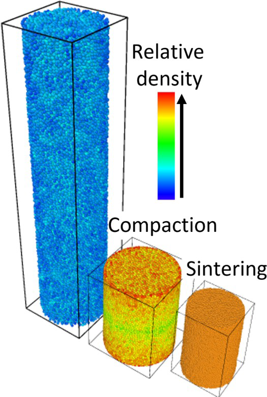
A Discrete Element Method (DEM) model is used to simulate the compaction and sintering of ceramic oxides. The process kinematics is decomposed into loading, unloading and ejection of the pellet. Interactions between the particles are considered elastoplastic by implementing a model able to tackle large densities. A simplified approach is used in the sintering stage, which focuses on the final part geometry rather than kinetics. The results are in good agreement with experimental data and FEM simulations from the literature regarding density gradient, elastic spring-back and final geometry. The simulations show that the friction coefficient between the agglomerates and the die is the primary factor for the density gradient in the pellet. This density gradient induces non-homogeneous sintering, which results in a final geometry with a diabolo effect. It is the first time that DEM reproduces this effect with the advantage of considering explicitly the particulate nature of the powder.
Keywords
Introduction
The finite element method (FEM) has received considerable attention for simulating powder compaction and sintering [1]. FEM is a numerical tool that allows solving the partial differential equations of the mechanics of a continuous media. Applied to powder forming processes, such as compaction and sintering, FEM uses elastoplastic or elasto-viscoplastic models [2] as constitutive equations. These simulations can consider the geometry and boundary conditions, such as pressing conditions and friction between the powder and dies. However, the models implemented in the FEM are derived from the mechanics of continuous media. They do not consider the particulate character of powders directly (i.e. the microstructure of powders and their composition is not considered explicitly). They cannot easily describe fracture phenomena of green compacts because they do not describe rearrangement, fracture of particles or debonding [2,3]. The complex particulate nature of the powder is generally taken into account by calibrating phenomenological models to experimental data. Therefore, each new powder needs to be characterised, which requires complex instrumented matrix tests performed at different compaction pressures and stress states.
The discrete element method (DEM) is an alternative simulation method that can be used to take into account powders’ granular microstructure directly. Initially introduced by Cundall & Strack [4] for geomaterials, the DEM consists of simulating a granular medium by taking into account each particle, generally represented by a sphere (Figure 1(a)). Contact laws with a normal and a tangential component define the interaction between the particles that indent each other (Figure 1(b)). The particle's motion is calculated to satisfy force and moment equilibrium. This method has been used mainly to simulate metallic [5–7], ceramic [8] and composite powders [9,10]. With DEM, it is possible to simulate the rearrangement and the plastic deformations during cold isostatic and closed die compaction of powders [6,11], as well as the fracture of agglomerates [12]. DEM has also been used to model sintering, taking into account diffusion as well as coalescence [13]. Thus, the DEM is a powerful method to simulate the entire process from compaction to sintering.
(a) Sketch of a discrete medium simulated by DEM with contact forces with normal (N) and tangential (T) components. (b) Two DEM particles of radius Ri and Rj indented (indentation δ) and forming a bond of size ab.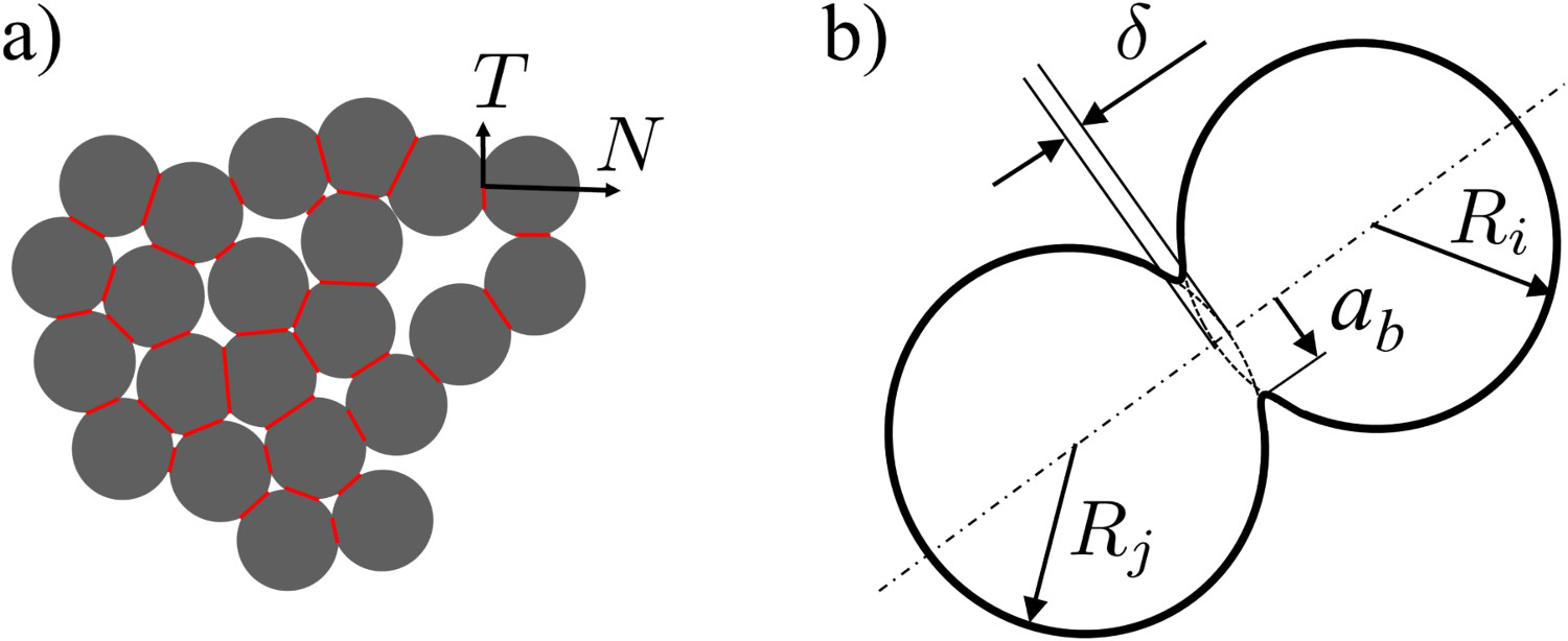
Although up to hundreds of thousands of particles can be simulated, the dimensions are too small to represent an industrial part. This explains why most DEM studies focus on a small volume of material and why finite element approaches have been adopted in the last 20 years to model real parts. Some methods propose a micro–macro coupling from microscopic DEM simulations to derive macroscopic constitutive relations [14].
The computation time can be significantly reduced by using GPU parallelisation [15]. Computation time can also be reduced by simulating fewer particles that are larger than the size of the real particles. In that context, the present study reports on a method for DEM to simulate a macroscopic compact by considering particle agglomerates instead of crystallites or unit particles. Interactions between the particles are considered elastoplastic. We use this method to simulate the compaction and sintering of uranium oxide powder at a macroscopic scale. A double-action dry pressing has been implemented for the compaction stage, and its process kinematics are decomposed into loading, unloading and ejection of the pellet. After the compaction, the pellet is sintered at a temperature of 1700°C.
The present study couples with the DEM simulations of compaction, ejection and sintering to deliver the final shape of an industrial part. This methodology has been employed previously with FEM [16]. To our best knowledge, this is the first time it has been attempted with DEM. The advantage of DEM is that it brings a wealth of information that FEM cannot provide and that it uses constitutive contact laws that explicitly take the granular nature of the powder into account.
Model description
A typical ceramic microstructure is composed of crystallites, aggregates and agglomerates. The size of these entities depends on the ceramic powder, but typically, crystallite size is in the range of hundreds of nanometers. Porous aggregates made of strongly bonded crystallites are micronic, while agglomerates made of weakly bonded aggregates have a broader range, varying from a few to hundreds of microns (Figure 2). P. Pizette et al. [17] have studied crystallite and aggregate length scales with DEM.
(a) Crystallite, aggregate and agglomerate length scales for DEM simulations (P. Pizette [17]). (b) An agglomerate represented by a single DEM sphere used here.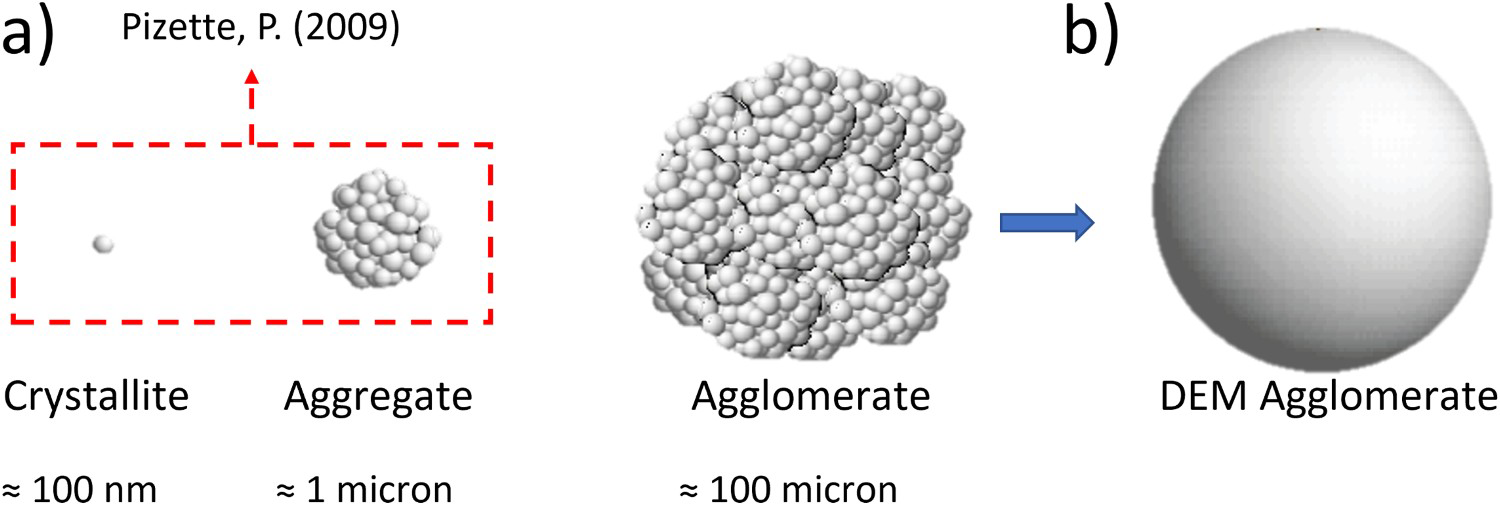
An entire system can be simulated by using the agglomerate length scale without requiring billions of unit particles (as required by the simulation at the crystallites or aggregates scale). In that case, one agglomerate is considered as one single porous particle for DEM. This approach may represent particle deformation and rearrangement well, but it cannot represent agglomerates fracture explicitly. Figure 2 summarises this approach, which is implemented in dp3D, an in-house code mainly used for material science applications.
In DEM, a contact force law is required for computing the total force applied on each particle. It gives the normal force N as a function of the mutual indentation δ between the two particles (Figure 1(b), Figure 3). Forces are shown positive when repulsive. During the loading of a contact, no elastic domain is considered, owing to the weak nature of agglomerates. The plastic loading is adapted from the high-density model proposed in [18]. Consider a material characteristic of the agglomerate in which uniaxial stress response writes:
Evolution of a contact between two agglomerates using an elastoplastic model. A contact may be plastic if the overlap increases through time and is irreversible or elastic if unloading arises. A contact may snap if this overlap decreases further than a critical value. Note how the unloading stiffness increases as the plastic indentation increases.
 is a plastic parameter,
  the axial strain and m a hardening parameter. The normal repulsive force (
 ) for two particles, i and j, at time
  is:
is:

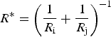
 is the contact stiffness, which is a sum of two terms,
  and
and  :
:
 is the equivalent radius for particles i and j:
 , and the plastic parameter
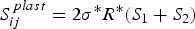
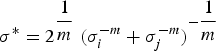
  , are material parameters that have to be fitted with the experimental density-stress curve: the hardening parameter changes the curvature of the loading curve in shown in Figure 3, and the stress parameter changes its amplitude. When considering a contact between two different materials with plastic parameters
  and
and  ,
,  writes:
 in Equation (3) is preserved from [18], and depends on the indentation
  at the contact. The term
  depends on the local relative density, and is adapted to consider porous agglomerates:
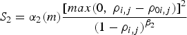
 is a function of the hardening parameter m [18],
  is a parameter that depends on the porosity of the agglomerates,
  is the local density around the particles and
  is the initial local density (before plastic indentation). Note that when
  tends to unity,
  tends to infinity to model incompressibility. The local density
  is computed using Voronoi tessellations with the Voro++ package [19]. Equation (6) allows some hardening of the particulate material to be taken into account due to the local densification. This is in contrast with standard DEM schemes that only consider the mutual indentation between particles.
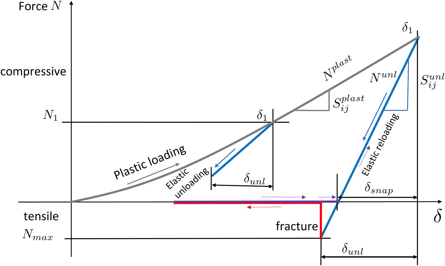
Elastic unloading is written by considering an elastic stiffness  :
:
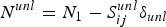
 is the force at the maximum plastic indentation
  and
and  is the amount of indentation retrieved elastically (
 , Figure 3). The elastic stiffness is modelled by considering that a bond has been formed between the two particles during plastic loading and using the model of Jefferson et al. [17,20]:
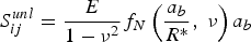
 is the Young's Modulus,
  the Poisson's ratio and
  the radius of the bond formed during the plastic loading
 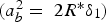 .
.
The elastic unloading thus depends on the elastic parameters of the agglomerates and on the size  of the bond. In other words, the elastic stiffness of an unloading contact depends on its plastic history. The function
  has been derived by Jefferson et al. [20] and typically increases from 1 to 1.3 as the relative size
  increases. The plastic loading stiffness is capped by the unloading stiffness
 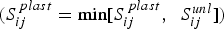 to ensure that the plastic response is never stiffer than the elastic one.
The bond formed during plastic loading may sustain tensile forces as sketched in Figure 3. The force necessary to break this bond,  , depends on how much the agglomerates indented each other:
 is the tensile strength, to be fitted with experimental data. For the time being, no shear strength is introduced in this model. Bonds only fracture in tension. When the tensile force
  reaches
  the bond breaks and no force is transmitted anymore. If the contact resumes, it will only transmit repulsive force when
  , with
  given by:

 is reached during reloading, the contact reloads elastically following the
  branch in Figure 3, until the indentation increases above
  and the contact re-plastifies.
The tangential force model is composed of a sticking mode and a sliding mode. The sticking mode uses the Hertz-Mindlin model while during the sliding mode, the tangential force is limited by Coulomb friction. Two friction coefficients are used: the friction between agglomerates ( ) and the friction between the agglomerates and the die (
 ). The DEM literature has already studied the effects of these friction coefficient on the powder response [21,22]. In particular, their role on the fluidity (the ratio between the radial and axial stresses) and on the density gradient in the compact have been reported.
The Bouvard Pan model [23,24] is used for the sintering stage. This model takes into account grain boundary and surface diffusion but does not consider grain growth. The details of the DEM model implementation of the sintering model can be found in [25]. In short, the model introduces a normal force  :
:
 is the contact radius,
  is a diffusion parameter (grain boundary limited) and
  is the surface energy. The first term on the RHS of Equation (11) is the viscous response of the contact while the second term is always tensile and accounts for the sintering shrinkage.
Here, because we model sintering at the scale of agglomerates that are much larger than the actual grains, the kinetics of sintering are not correct (we use alumina material parameters that can be found in [13]). However, the relative densification kinetics (regions of large relative density shrink slower than regions of small relative density) should be correctly rendered. Thus, the final geometry of the sintered compact should be appropriately modelled.
Process kinematics
A uranium oxide powder was chosen to simulate the compaction and sintering process. The geometric relative density in the simulation (as if indented spherical discrete elements were dense) is multiplied by a factor 0.45 to obtain the relative density of the compact, thus considering the porosity of agglomerates. The 0.45 value is close to the value (0.41) of density measured by mercury porosimetry by [26]. It also has the advantage of leading to an initial geometrical density (0.4) with a realistic coordination number (2.5). The ceramic powder with an initial relative density of 0.18 and 40 000 particles representing agglomerates is introduced into a cylinder die of approximately 10 mm in diameter and 40 mm in height. Figure 4 summarises the process kinematics. The powder is pressed by two flat punches (double-action dry pressing, same force on the upper and lower punch) up to an axial stress of 600 MPa (1). The upper punch is then unloaded until the axial stress reaches 50 MPa (2). This accompanying stress is maintained during ejection, during which the cylinder slides out of the die (3). Finally, the upper punch is completely unloaded (4).
(a) Process kinematics of the compaction process implemented for DEM simulations, (b) DEM compact before compaction, after compaction and after sintering.
Results and discussion
Compaction
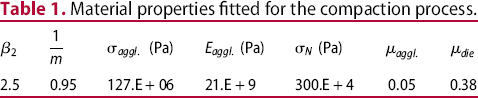
 to ensure that contact forces between the agglomerates and the dies are dictated by the soft agglomerates (Equation (5)). The Young's modulus of the die is set to 550 GPa, which is typical of tungsten carbide. Table 1 shows the material properties used for the compaction of uranium oxide. Each material parameter can be fitted using a given stage of the compaction process. The
  and
and  parameters (Equation (1)) are fitted using the compaction curve as they essentially control the axial stress response. The
  parameter (Equation (6)) controls the asymptotic increase of the stress when the powder approaches full density. It is also fitted using the axial stress response.
  and
and  (Equations (8)–(9)) are fitted using the experimentally measured axial spring-back of the compact after ejection. The friction coefficients are fitted using the ratio between the radial and axial stresses during compaction (experimentally measured) and using the density gradient in the compact (obtained from FEM simulations [27]), as detailed below. After compaction,
  evolves and a very large value is adopted to better fit with experimental data.
Material properties fitted for the compaction process.
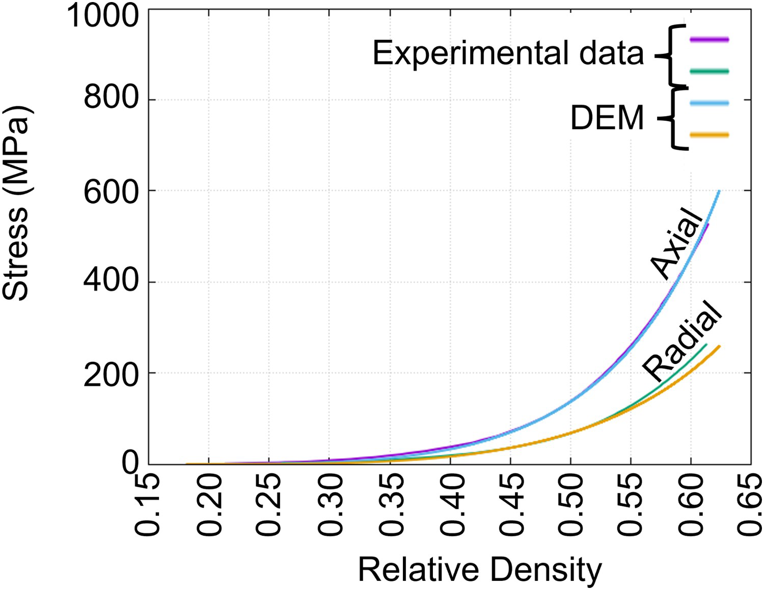
The axial and radial stress evolution are shown in Figure 5 for the loading stage. The experimental data originates from [8]. A good fit is obtained with the values of m, Axial and radial stress during load for experimental data [8] and DEM simulation of UO2 powder. Influence of agglomerates’ friction coefficient  and
and  of Table 1. Because we have access to both the axial and radial responses of the powder, we are able to fit the friction coefficient in the powder (
 ). Although less good, the fit for the radial stress is reasonable. The powder fluidity (the ratio between radial and axial stresses) is approximately 0.5, which is typical of ceramic powders. The friction coefficient in the powder (
 ) is the main parameter that controls fluidity. Figure 6 shows that a larger friction coefficient is associated with a smaller fluidity. This may indirectly model the performance of an internal lubricant or of the roughness of agglomerate surface.
 . Increasing the value of this material parameter results in a less fluid powder.
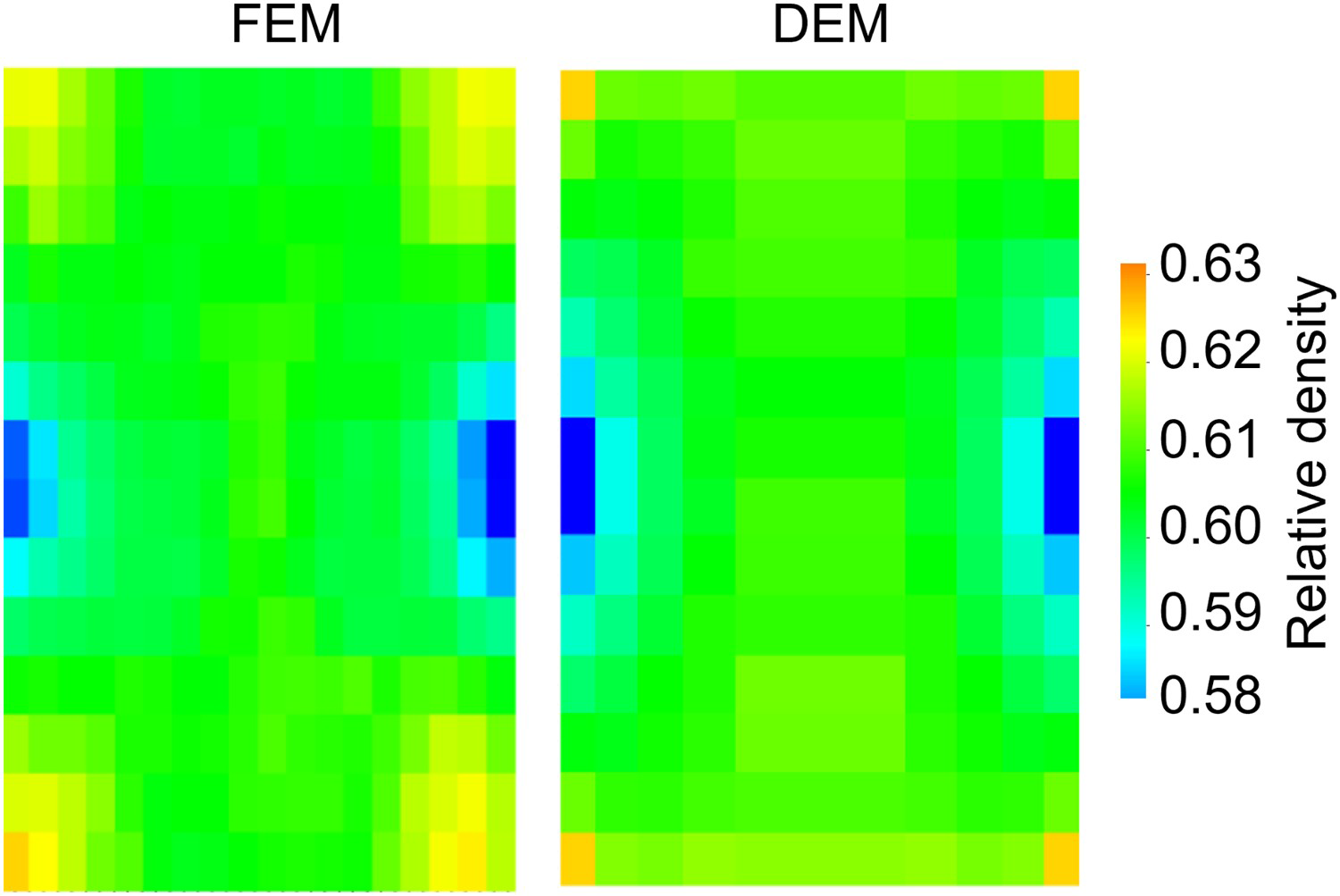
DEM simulations give access to the density gradient after the loading stage. For double action pressing, no experimental data is available. Thus, the density gradient of the pellet cross-section is compared with FEM simulations [27] in Figure 7. Although DEM simulations give 3D information, we present a 2D map to compare with axisymmetric FEM simulations. DEM simulation shows a good qualitative agreement with FEM simulation. For both methods, a larger density is predicted in the corners of the cylindrical pellet and a smaller density at the radial extremity at mid-height. This gradient is mainly dictated by the friction between the powder and the cylinder die. Figure 8 indicates that increasing Density gradient of the pellet cross-section after loading for FEM (adapted from [27]) and DEM simulations. 2D density gradient of a 3D compact: influence of the friction coefficient between agglomerates and the cylinder die  leads to a more pronounced density gradient. The value of
  is a measure of the performance of the die lubrication. We have observed that after loading, the density gradient continues to evolve slightly during unloading and ejection.
 .
.
Elastic energy has been stored in the pellet during compaction. The DEM elastic unloading model (Figure 3, Equations (7) and (8)) allows the axial and radial spring-back to be simulated. The amount of spring-back is essentially affected by process kinematics (axial compaction stress) and material parameters ( and
and  in Table 1). We have observed that after pellet ejection, axial and radial elastic spring-backs are 4% and 1%, respectively. These results are in good agreement with experimental data. The DEM simulation shows also that the pellet diameter varies slightly with the pellet height and that this variation is directly linked with the density gradient of the pellet. Experimental data could not detect or confirm this slight variation of 25 microns. Note that this diameter variation is in qualitative agreement with FEM.
Sintering
The green compact obtained from DEM is sintered up to a relative density close to unity. The final sintered geometry strongly depends on the density gradient. Sintering is slower in the regions where the local density is high and is faster in the regions where the local density is low, as the driving force for sintering scales with the remaining porosity. It generates an inhomogeneous final geometry in the pellet, the so-called diabolo effect: it densifies more in the middle of the pellet than in the top and bottom. This diabolo effect's amplitude is 40 µm for the DEM simulation and 35 µm for the experimental data. Even though alumina thermal properties were used for the sintering process, the DEM simulation presents satisfactory results regarding the final pellet geometry. After sintering, DEM simulation indicates that a slight density gradient is still present in the pellet. This result could not be corroborated with experimental data.
Conclusion
A new DEM model was used to simulate the compaction and sintering of ceramic powders at the scale of a whole part. DEM has been chosen because it can directly take into account the powder's granular microstructure, simulating the rearrangement and the plastic deformation of agglomerates. The model chosen considers an agglomerate as a single discrete element, reducing the total number of particles to be simulated and decreasing the computational cost. Results demonstrate that an entire system can be simulated using only agglomerates without requiring billions of particles. A good agreement with experimental data and FEM simulations regarding stress-density curve, density gradient, elastic spring-back and final geometry is obtained. As classically observed experimentally [28,29], the DEM simulations show that the friction coefficient between the powder and the die is the primary factor for the density gradient in the pellet. DEM simulations indicate the presence of a diabolo-effect right after ejection, and it occurs due to a non-homogenous spring-back caused by the density gradient. During the sintering process, this density gradient induces non-homogeneous densification, which results in a final geometry with a so-called diabolo effect.
This work is a proof of concept for DEM to correctly simulate the evolution of a ceramic powder from the compaction stage up to the sintered stage at the length scale of an industrial part. The advantage of DEM is that a more realistic representation of the powder is modelled. In particular, DEM could be used to model composites, to investigate the effects of the initial density (before compaction) or of size distribution. Still, it should be clear that the material parameters used in the simulations need some fitting and that an experimental characterisation is still necessary.
Footnotes
Disclosure statement
No potential conflict of interest was reported by the author(s).