
Abstract
Microstructural characteristics and wear properties of Fe-16Mn-10Al-5Ni-0.86C lightweight steel (LWS) manufactured by laser powder bed fusion (LPBF) process were investigated and compared with conventional LWS. Both LWS alloys constituted an austenite matrix and B2-IMC. The LPBF LWS sample showed polygonal-typed B2-IMC, whereas conventional LWS had rod-typed B2-IMC. The ball-on-disk method was used to perform a wear test at 25°C under three different load conditions of 20N, 3N and 40N. The wear results indicated that the LPBF LWS sample exhibited a similar amount of wear loss under the 20N and 30N load conditions, but it showed better wear resistance under the 40N compared to conventional LWS. After the wear test, the abrasive wear behaviour was confirmed as the main wear mechanism in both LWSs. The formation of oxide layers and debris was analysed through observation of the cross-sectional area of the worn surface.
Introduction
Fe-16Mn-10Al-5Ni-0.86C lightweight steel (FeMnAlNiC LWS) is an austenite + B2 intermetallic compound (IMC) duplex steel developed by adding Ni to Fe-Mn-Al-C alloy [1]. The density of this alloy is 6.82 g/cm3, which is 13% lighter than the density of low-carbon steel (7.8 g/cm3). In this material, manganese and nickel are utilized to stabilize the austenite, and manganese also improves the solubility of aluminium. Aluminium decreases the density of LWS (appx. 1.5% per adding 1 wt.%) and forms B2-IMC together with Ni, allowing more B2-IMC to be formed [1–7].
Fe-Mn-Al-Ni-C LWS can induce the B2-IMC by quenching at temperatures between 920°C and 950°C [1,7–9]. If B2-IMC forms fine on the deformation band or twin boundary in the grain, it is known to increase the yield strength and tensile strength by preventing the movement of dislocations during deformation. When B2-IMC particles in a material coarsen, it can have a detrimental impact on the mechanical properties of the material. As the size and number of B2-IMC particles increase, the material's mechanical properties can be adversely affected in multiple ways. The coarse B2-IMC particles can act as stress concentrators and cause localized plastic deformation and eventual fracture, leading to a reduction in the material's properties. Moreover, the formation of brittle intermetallic compounds due to B2-IMC coarsening can lead to crack initiation and propagation, further deteriorating the mechanical properties of the material. This is because intermetallic compounds are more likely to crack under stress, resulting in premature failure of the material. B2-IMC achieves outstanding corrosion resistance as well as wear resistance because it has high-strength characteristics and stable structures. Due to this, lightweight steel has great potential in national defence, transportation and aviation applications [1,2,7–10]. The conventional manufacturing methods for Fe-Mn-Al-Ni-C LWS require more time and money, especially when producing complex components that involve additional processes such as extrusion, forging and casting.
Additive manufacturing (AM) is a process that manufactures 3D parts based on computer-aided design (CAD) models of shapes that nearly resemble the final shape, which has the advantages of manufacturing parts with complex shapes, optimization of part topology, part consolidation and decreasing material loss [11–14]. Therefore, many attempts have been made to manufacture low-carbon steel, high-carbon steel, high-manganese steel, aluminium, titanium and high-entropy alloy, and articles investigating the microstructure and mechanical properties are being presented [11,12,14–21]. Laser powder bed fusion (LPBF), which is a well-known metal AM process that uses a high-powered laser to selectively melt and fuse metal powders together layer by layer. The process allows for the creation of complex geometries and structures with high accuracy and precision [22]. In contrast to other conventional methods, LPBF processing frequently necessitates no post-processes, such as mechanical tooling, and as a result, demonstrates significant flexibility. When the LPBF process is applied to Fe-Mn-Al-Ni-C LWS, multiple potential precipitate sites for B2-IMC, leading to the expectation that unique microstructures that could not be achieved with conventional manufacturing processes will be formed. However, some researchers have studied on the wear resistance of Fe-Mn-Al-C LWS. Acselrad et al. [23] studied that the Fe-Mn-Al-C austenitic steel has similar wear resistance to both the 304 stainless steel and the M2 tool steel. According to Peng et al. [24], the wear rate of Fe-25.1Mn-6.6Al-1.3C steel was examined under different heat treatment conditions. They discovered that the hardness, mechanical properties and wear resistance of the steel were influenced by the size and distribution of κ-carbides. The researchers discovered that when the steel was aged for approximately 2 h at 550°C, fine κ-carbides with nano-scale sizes were formed within and on the austenite grain boundaries, which resulted in improved wear resistance. Understanding the friction and wear behaviour of lightweight steel is essential for expanding its application range and enhancing its reliability and stability, particularly in challenging environments.
In this present study, Fe-16Mn-10Al-5Ni-0.86C lightweight steel (LWS) was manufactured using a laser powder bed fusion (LPBF) method, and its microstructural and wear properties were investigated and compared with those of conventional hot-rolled LWS. Additionally, this study examined the wear behaviour of LPBF LWS by considering microstructural factors.
Experimental methods
Fe-Mn-Al-Ni-C master alloy was used to prepare the powder feedstock for LPBF in this work, and it was melted under a vacuum and atomized with Ar gas. The laser diffraction technique was used to determine the powder particle size. Most of the produced powders had a spherical shape. The laser diffraction technique (Mastersizer 3000) was used to determine the particle size, and measurements were D10: 7.11 μm, D50: 18.66 μm and D90: 35.21 μm, respectively.
The LPBF process was carried out in a high-purity Ar environment (purity: 99.995%) with Mlab cusing (Concept Laser GmbH, Germany) equipment. During the LPBF process, the laser power was set to 90 W, the laser scanning speed was set to 450 mm/s, and the layer thickness was set to 25 μm. To prevent mechanical anisotropy, the rotation angle between the (n) layer and (n + 1) layer was applied at 17°, with a bi-directional scanning strategy and using a chessboard pattern. Based on the aforementioned parameters, the volumetric energy density (VED) was calculated using Equation (1).
For microstructure observation, specimens were polished using #400 –#1200 grit silicon carbide paper, followed by mirror polishing using 1 μm diamond suspension and colloidal silica (CS) suspension. FE-EPMA (Field Emission Electron Probe Micro Analyzer, JXA-8530F Plus) confirms for alloying element distribution. For constituent phase analysis, an X-ray diffractometer (XRD, Ultima IV, Cu K2 radiation, scan step size: 0.02 deg., scan rate: 2 deg. min-1) was used. Also, FE-SEM (MYRA 3 XMH, Tescan, Czech Republic) with high-resolution electron backscatter diffraction (HR-EBSD, Nordlys-CMOS detector, binning 2 × 2, Oxford, United Kingdom) was used for crystallographic orientation, grain size and phase fraction measurements.
To conduct the wear test, the above materials were machined into cuboid shapes of 10 (L) mm × 10 (W) mm × 5 (T) mm. A tribometer (J&L Tech, Korea) was used to conduct a ball-on-disk dry wear test with conditions of normal force (N): 20, 30 and 40, rotation speed: 0.1 m/s, track radius: 4 mm and loading time: 2000 s at a 25°C. Tests were conducted three times with each condition, and wear loss was measured using an electronic scale with 0.1 mg resolution.
Initial microstructure characteristics of Fe-Mn-Al-Ni-C lightweight steels
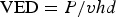
Figure 1 shows EBSD phase maps and KAM (kernel average orientation) maps of the BD plane of the LPBF-built LWS and ND plane of the conventional LWS. According to the phase map of both materials, the microstructure of LPBF-built LWS exhibited homogeneously distributed of fine (0.45 μm) B2-IMC within the austenite grains. However, in the case of conventional LWS, the heterogeneous distributed B2-IMC consisted of band-like shape (average length: 13.4 μm) and finer rod type B2-IMC (average length: 5.1 μm) within the austenite grains. Meanwhile, the fraction of B2-IMC in both LWSs was analysed 13.4% (LPBF LWS) and 39.9% (conventional LWS). It is notable that the LPBF LWS shows different size and fraction in B2-IMC compared with conventional LWS. It is presumably due to the rapid cooling demonstrated by high-power laser during the LPBF process. Nano-scale B2-IMC mainly precipitates at the unstable region within grain such as twin boundary and deformation band by quenching. In the case of conventional LWS, annealing is performed at temperatures around 900°C to induce this effect [1,23,24]. On the other hand, repeated irradiation of a high-power laser during LPBF process causes repeated melting and rapid-cooled solidification, and it is reported that dislocations can be integrated to compensate for the contraction caused by the rapid cooling [22]. The homogeneously distributed fine B2-IMC within the austenite grains observed in the LPBF LWS is a desirable microstructure for improving the material's mechanical properties. This is because a uniform distribution of fine particles can effectively hinder dislocation motion, resulting in enhanced strength and ductility. In contrast, the heterogeneously distributed B2-IMC in band-like shapes and finer rod types found in the conventional LWS can act as preferential sites for crack initiation and propagation, which can lead to reduced mechanical properties and decreased material reliability. The KAM map depicted in Figure 1(a2,b2) presents the both LWSs show high KAM value distribution near B2-IMC boundaries. High KAM value distribution is also found near sub-grain boundaries (white line) in the austenite grain in the case of the LPBF LWS.
EBSD showing austenite matrix and BCC-B2 phase map of LPBF LWS (a1) and Conventional LWS specimen (b1) and Kernel Average Misorientation (KAM) map ((a2), (b2)), and ((a3), (a4)), ((b3), (b4)) showing size distribution of constitutive phases of both LWSs.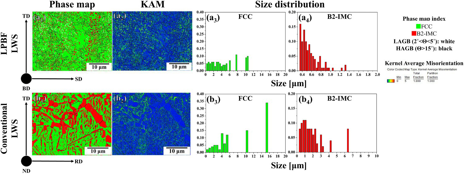
Through the XRD analysis results depicted in Figure 2, the constituent phases of the LPBF-built LWS and conventional LWS were identified. As a result, the γ-austenite and B2-IMC phases observed in the EBSD phase map were identified as identical. The LPBF LWS presents a broaden peak compared to the conventional LWS, which can contribute to the dislocation pile up mentioned in the paragraph above and sub-grain boundary formation. The broadened peak observed in the XRD analysis of the LPBF LWS is an indication of a smaller crystallite size and a higher density of defects, such as dislocations and vacancies, compared to the conventional LWS. This is due to the rapid solidification rate and high cooling rate during the LPBF process, which results in a finer microstructure and more defects. The presence of these defects and the formation of sub-grain boundaries can have a significant impact on the material's mechanical properties. The increased density of defects can hinder dislocation motion and contribute to strain hardening, resulting in improved strength and ductility. The formation of sub-grain boundaries can also act as barriers to dislocation motion, effectively strengthening the material. B2-IMCs were represented by FeAl and NiAl, and they have compositions that are different from δ-ferrite.
XRD analysis results for LPBF LWS (black line) and Conventional LWS (red line) showing (a) constituent phases and (b) FWHM of both LWSs.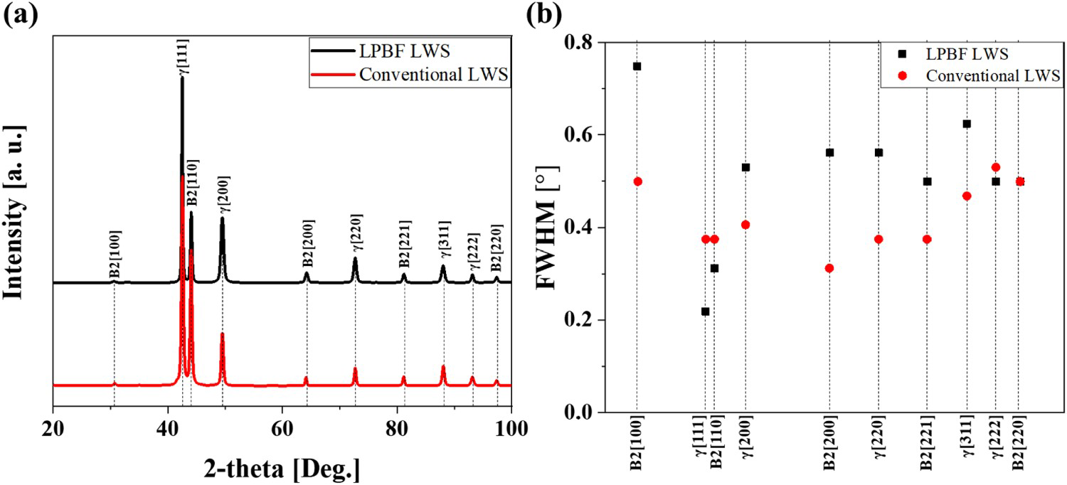
EPMA mapping in Figure 3 indicates the element distribution. The LPBF LWS has an uneven distribution of Fe, Mn, Al, Ni and C elements, whereas the conventional LWS reveals the elements evenly distributed in the matrix, which is more similar to the EBSD phase map. Therefore, based on aforementioned results, both LPBF-built and conventional LWSs show differences in size and fraction of B2-IMC due to differences in manufacturing process, and a phenomenon that looks different from other surfactants. The inhomogeneous distribution of Fe, Mn, Al, Ni and C elements in the LPBF LWS is due to the complex thermal history and rapid solidification rate during the LPBF process. The EPMA mapping results show that these elements are not uniformly distributed throughout the microstructure and can concentrate in certain areas. The uneven distribution of these elements can have a significant impact on the microstructure and properties of the material. Such as the concentration of Al and Ni at the grain boundaries can promote grain boundary strengthening, resulting in improved mechanical properties. On the other hand, the concentration of C in the interdendritic regions can lead to the formation of carbides, which can reduce ductility and toughness.
EPMA analysis results showing the distribution of alloying elements in the initial microstructure of LPBF-built LWS and conventional LWS.
Figure 4 and Table 1 show wear test results of the LPBF LWS and conventional LWS. Figure 4(a) is the average wear loss per load condition. In the 20N condition, LPBF and conventional LWSs obtained average wear losses of 3.0 ± 0.2 mg and 2.9 ± 0.2, respectively. The average wear value obtained under the 30N condition was 4.3 ± 0.2 mg (LPBF) and 4.2 ± 0.2 mg (Conventional), and no significant difference was found. In the load condition of 40N, the wear loss of LPBF LWS was 5.1 ± 0.2 mg, which was lower (higher wear resistance) than the conventional LWS with 5.5 ± 0.1 mg. Based on the results above, load condition of 20N and 30N confirmed that conventional LWS had approximately similar wear resistance compared to LPBF LWS. On the other hand, LPBF LWS exhibits better wear resistance than conventional LWS under the condition of 40N. Figure 4(b) depicts the wear rate by load conditions. The wear volume reflects conditions where wear occurred on the counterpart ball, and wear volume was calculated using the following equation according to ASTM G99-05 [25].
Weight loss for LPBF and conventional LWSs with different wear load conditions. Chemical compositions of initial powders, LPBF LWS and conventional LWS (wt.%). Comparison of wear loss values and wear rates of LPBF and conventional LWSs with different load conditions.
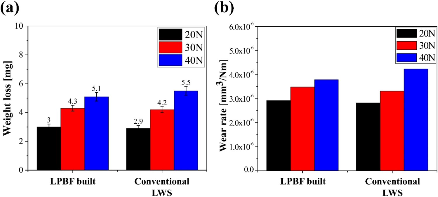

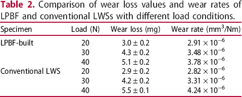
Figure 5 shows the coefficient of friction (COF) of LPBF LWS and conventional LWS according to wear load conditions. In the case of the LPBF LWS, no significant change in COF was observed as the load increased to 20N and 30N. In the case of the conventional LWS, COF was decreased as the wear load increased from 20N to 30N. However, the COF values of both alloys became similar under the wear condition of 40N. Meanwhile, the influence of the test load on COF is explained using the friction heat generation equation below.
Friction coefficient variation of Fe-16Mn-10Al-5Ni-0.86C LWSs.
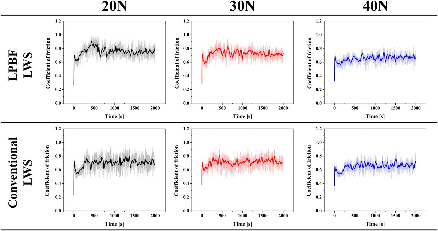
Figure 6 depicts the worn track SEM images of the two materials in each condition. The images reveal the presence of debris and flakes resulting from sliding as well as adhesion of debris on the worn surfaces of both materials. Based on the worn track observation, LPBF LWS and conventional LWS were determined to have identical adhesive wear behaviours at 20N and 30N. However, the worn surface of LPBF LWS at 40N load condition showed spallation, which is a different wear behaviour compared to the 20N and 30N conditions.
SEM observation results for the wear track surfaces of (a) LPBF LWS and (b) conventional LWS.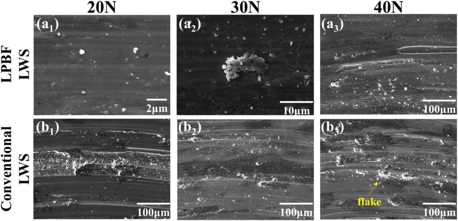
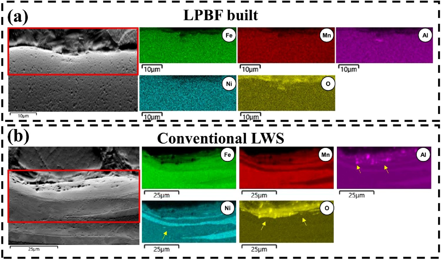
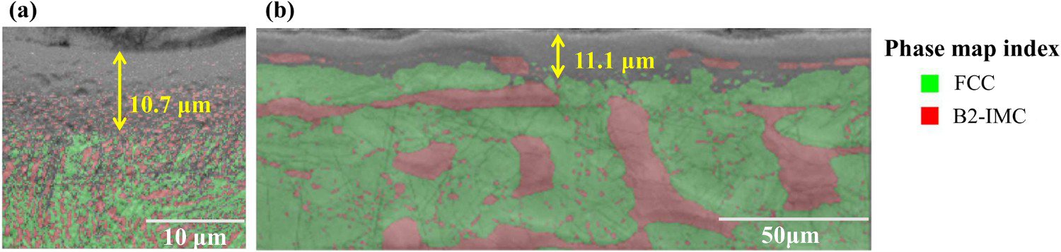
Figure 7 depicts the high magnification SEM image and EDS mapping of worn tracks after the wear test at 40N of both LWS alloys. The observations identified that the debris, flakes and adhesion layer of LPBF LWS and conventional LWS were composed of Al2O3. Due to the tribochemical reaction between the alumina balls and the Fe-Mn-Al-Ni-C LWS sample surface, an Al2O3 layer was formed. Furthermore, during the wear test, as the alumina balls slide against the sample surface, the resulting high shear stresses and frictional heat cause the diffusion of oxygen atoms from the environment into the sample surface. The presence of the Al2O3 layer plays a significant role in reducing contact between the counterpart and the matrix, effectively preventing further peeling off the matrix and contributing to an improvement in wear resistance. Additionally, the existence of homogeneously distributed (Ni, Al) intermetallic compounds on the worn surfaces, which exhibit high hardness and further enhance the wear resistance of the LWS Figure 8 shows cross-sectional SEM-EDS analysis results of the wear surface after the wear test at 40N of both LWS alloys. It is notable that oxides were formed in the austenite matrix through the Ni element map in the conventional LWS. Based on these results (Figure 8), it was thought that the matrix of conventional LWS would show lower wear resistance compared to LPBF LWS. Figure 9 shows the EBSD phase map with BSEI image. The zero solution of an EBSD map can appear if a diffraction pattern is not detected due to plastic deformation and lattice distortion. The depth for zero solution region of the cross-sectional area was measured 11.1 μm in the conventional LWS, which was deeper than the LPBF-built LWS at 10.7 μm. In addition, considering the phase fractions of initial microstructures and EDS maps of Figure 8(b), the larger size and higher fraction of B2-IMC in the conventional LWS is expected to result in a relatively lower Ni content in the austenite matrix than LPBF LWS. Nickel is often added to steel as an alloying element to improve its mechanical properties, including its hardness, strength and toughness [25]. In the case of wear resistance, the addition of nickel can increase the hardness of the material by promoting the formation of hard, wear-resistant phases such as carbides and nitrides. Nickel also has a beneficial effect on the wear resistance of steel by improving its ability to resist plastic deformation and cracking, which are two common wear mechanisms. In other words, the conventional LWS exhibits higher wear resistance due to the B2-IMC, but in the 40N load condition, abrasive wear of austenite dominates, leading to higher weight loss (lower wear resistance) compared to LPBF LWS.
SEM images and EDS results of the wear track surfaces and debris in the 40N load condition. (a) LPBF LWS and (b) conventional LWS with EDS mapping analysis of the debris adhesion region. SEM images and EDS results of the cross-sectional images of wear track areas and debris in the 40N load condition. (a) LPBF LWS and (b) conventional LWS with EDS mapping analysis of the debris adhesion region. EBSD analysis results of cross-sectional view of worn surface in the 40N wear condition; (a) LPBF LWS and (b) conventional LWS.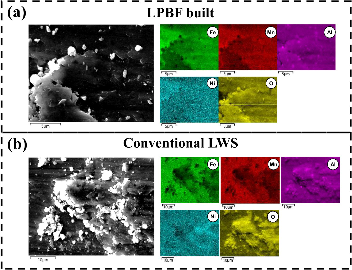
In this study, Fe-16Mn-10Al-5Ni-0.86C lightweight steel (LWS) was manufactured using a laser powder bed fusion (LPBF) process, and its microstructural and wear properties were examined and compared to those of (conventional) hot-rolled LWS, and came to the following conclusions:
The homogeneous microstructure, finer grain size and homogeneous distribution of fine (0.45 µm) B2-IMC were observed in the LPBF LWS sample. In contrast, the heterogeneous distributed B2-IMC consisted of band-like shape (average length: 13.4 μm) and finer rod type B2-IMC (average length: 5.1 μm) within the austenite grains in conventional LWS. Additionally, the fraction of B2-IMC in both LWSs was measured 13.4% (LPBF LWS) and 39.9% (conventional LWS). The presence of homogeneously distributed fine B2-IMC within the austenite grains in the LPBF LWS represents a favourable microstructure for enhancing the mechanical properties of the material. Wear tests at 20N and 30N conditions show similar weight loss values in both lightweight steels, but in the 40N condition, LPBF LWS identified better wear resistance than the conventional LWS. The wear rate exhibited a consistent increase as the load progressively increased. Comparison of wear rates confirmed that LPBF LWS had lower values (higher wear resistance) than the conventional LWS in the 40N condition. In both materials, the friction coefficient value gradually decreased as wear load increased. Worn surface and cross-sectional area of worn surface observations confirmed that those both LWS showed abrasive wear behaviour, and Al2O3 debris was observed on the cross section. In the case of the conventional LWS, a thick Al2O3 layer was observed on austenite matrix at the 40N condition. EBSD analysis of the cross-sectional area at 40N load condition confirmed that the LPBF LWS represents higher wear resistance of austenite matrix. Future work will be focused on the effect of varying the composition of LPBF LWS on its microstructure and wear properties. This would allow for a deeper understanding of the relationship between composition, microstructure and wear behaviour, providing valuable insights for further optimization and development of LPBF LWS materials.
Footnotes
Disclosure statement
No potential conflict of interest was reported by the author(s).