
Abstract
Nickel-based superalloys are currently the material of choice for use in high-temperature applications due to their excellent high-temperature strength. It is understood that many mechanisms contribute to this property, but debate exists regarding how to model these mechanisms and predict the overall strength. This review covers the different strengthening mechanisms occurring in polycrystalline Ni-based superalloys and how these may be modelled, with the aim of revealing the gaps in the literature. It is found that models for precipitation and coherency strengthening are particularly controversial, and a unified model for the yield strength of superalloys is missing from the literature. This is of commercial importance for the design of new alloys with superior mechanical properties to those currently available.
This review was submitted as part of the 2018 Materials Literature Review Prize of the Institute of Materials, Minerals and Mining run by the Editorial Board of MST. Sponsorship of the prize by TWI Ltd is gratefully acknowledged.
Introduction
Nickel-based superalloys are currently the ubiquitous materials for use in the hottest regions of the gas turbine engine, due to their exceptional strengths at high temperature. However, the drive to reduce the cost and environmental consequences of air travel, while increasing the flight speed, is pushing the limit of current materials technology. These demands may be met by operating the gas turbine engine at higher temperatures, above the current limit of Ni-based superalloys. To design new alloys for this purpose, the underlying strengthening mechanisms must be fully understood and able to be predicted. This would therefore enable the design of new alloys with microstructures tailored specifically to optimise the strengthening mechanisms known to be occurring.
The microstructure of Ni-based superalloys consists of a matrix of disordered, face-centred cubic (FCC) γ phase containing a large volume percent ( ) of coherent, ordered
  phase precipitates (Ni
 (Al,Ti)). This precipitate phase is also cubic, with the L
 structure (Strukturbericht notation).
The exceptional high-temperature mechanical properties of these alloys can be attributed to the Experimental data for some current Ni-based superalloys showing increasing yield strength with a temperature of up to  phase, which, via multiple concurrent mechanisms, can improve the yield strength by up to a factor of 5 compared to the precipitate-free γ matrix [1]. The ordered nature of the
  precipitates also gives rise to a remarkable property of Ni-based superalloys – increasing strength with a temperature of up to
  C (Figure 1).
  C (yield stress phenomenon) [2]. Reproduced with permission from Cambridge University Press.
In polycrystalline alloys, a multimodal A bimodal distribution of secondary and tertiary  size distribution is generally desired. Depending on the processing route, primary
  precipitates of the order of 1 µmm may exist on grain boundaries, which prevent coarsening of the γ grains during both manufacture and service. Smaller secondary (∼200 nm) and tertiary (∼10 nm) precipitates (Figure 2) are present to offer strengthening via inhibition of dislocation motion.
  precipitates in a Ni-based superalloy.
Many of the strengthening mechanisms present in Ni-based superalloys have been studied extensively, but there remains a lack of consensus as to the extent of each effect. This review offers a broad summary of the various strengthening mechanisms known to occur in polycrystalline Ni-based superalloys, and how these may be modelled with the aim of predicting the overall yield strength. Only room temperature effects are considered in the scope of the present review. The aim of this review is to collate the literature, and to clarify the gaps in our present understanding of the strengthening mechanisms of Ni-based superalloys. With this in mind, this review can pave the way for a unified picture of these mechanisms, which is useful for alloy design to meet the future requirements of the aerospace industry.
Mechanisms of strengthening
The  precipitate size, composition and morphology all affect the resulting alloy strength. Ardell [1,3] described precipitation strengthening of superalloys as arising from five separate mechanisms; chemical, stacking fault, modulus, coherency and order strengthening. Chemical strengthening arises from the increased surface energy due to the new interface created when a precipitate is sheared by a dislocation. Stacking fault strengthening and modulus strengthening occur due to the different stacking fault energies and elastic moduli of the matrix and precipitate phase, respectively. In the former case, when the matrix and precipitate phases have different stacking fault energies, the separation of the two partial dislocations also differs within each phase, impeding the subsequent motion of the dislocations. In the case where the two phases have different elastic moduli, the dislocation energy will differ within each phase, thereby affecting its motion. Coherency strengthening occurs when the lattice parameters of the matrix and coherent precipitate phase differ, therefore causing a strain field to be set up surrounding the precipitate. Finally, order strengthening occurs when the precipitates have an ordered crystal structure, which is disrupted by a dislocation travelling through the precipitate, thereby creating an anti-phase boundary with associated energy (APBE).
Any of these mechanisms can be operative at one time, however, one may have a much more significant effect than the others in a particular alloy system, or depending on factors such as precipitate volume fraction or size. This is where the lack of consensus in the literature arises.
For example, Gerold and Haberkorn [4] and Decker [5] also name these same mechanisms as those affecting the yield strength of Ni-based superalloys, however, chemical strengthening is ignored since it predicts an overly large effect on the critical resolved shear stress (CRSS) at small particle sizes, which is not seen experimentally. This omission is not inconsistent with Ardell [3], who dismissed the effect of chemical strengthening by stating that this is likely to only be significant at very small precipitate sizes, if at all.
In this initial analysis of Ardell, order strengthening was described as the most significant of these processes [1]. In contrast, Ahmadi [6] has argued that the APBE and coherency strain are the most significant mechanisms for increasing the yield strength in alloy Allvac 718Plus, and Kozar et al. [7] concluded that APBE and the volume fraction of the tertiary  are the most important factors for increasing the strength of alloy IN100.
Coherency strengthening is also particularly controversial. Raynor and Silcock [8] describe it as negligible (with order strengthening dominant), whereas other studies [4,9,10] conclude that it is the major strengthening mechanism. There are also many examples in the literature between these two extremes [11–14].
Hereon, order and coherency strengthening are considered separately. Stacking fault and modulus strengthening are not considered within this review, since due to the very similar properties of the γ and  phases, these mechanisms contribute negligible strengthening in Ni-based superalloys [8,15,16]. Chemical strengthening is not discussed either, as this has been shown to have a negligible strengthening effect in Ni-based superalloys [15].
Of course, there are further strengthening mechanisms present in Ni-based superalloys, unrelated to the presence of  . These include solid solution and grain boundary strengthening. What follows is a more detailed overview of these individual strengthening mechanisms in polycrystalline Ni-based superalloys. Additionally, how to combine these mechanisms to give an overall measurable yield strength is another area of dispute covered in this review.
Solid solution strengthening
Ni-based superalloys contain many different elemental additions which may sit on the lattice sites of both the γ and  phases. Since the atomic radius of each added element differs to that of the major element – Ni, the crystal lattice is distorted around the substitutional solute atom. The resulting strain field interacts elastically with that of a dislocation, thereby impeding the motion of dislocations and increasing the strength relative to a pure Ni matrix. These interactions arise from both an atomic size misfit and an elastic modulus misfit [17]. The latter arises from the presence of hard or soft regions of the matrix, caused by the presence of solute atoms of differing stiffness to that of the matrix atoms. Although this is an assumption, it has been shown to result in a better fit to experimental data than when atomic size mismatch alone is taken as the source of strengthening [18].
The phenomenon of solid solution strengthening is commonly taken into account in the γ matrix phase [19,20], but is rarely considered in the  phase due to its ordered structure [7,21].
Precipitation strengthening
It is generally accepted that the amount of strengthening due to the addition of precipitates increases with the volume fraction of Dislocation pairs during in situ deformation of a Ni-based superalloy, showing characteristic looping around  particles [6]. Plastic deformation in the disordered γ matrix phase of Ni-based superalloys most commonly occurs by the passage of single dislocations of type
  or their associated partials (where a is the lattice parameter). However, the ordered structure of the
  precipitates means that the passage of a single dislocation of this type moves atoms into unfavourable, high energy positions, with an associated APBE. Therefore, once ordered
  precipitates are present in the microstructure, the dislocations must travel in pairs to restore the
  structure (Figure 3) [8].
  precipitates [22]. Reproduced with permission from Taylor & Francis Ltd.
The mechanism of plastic deformation in Ni-based superalloys depends on the size of the Cutting of  precipitates within the microstructure. When the particles are small (in under-aged and peak-aged alloys), deformation occurs by pairs of
  type dislocations cutting through the precipitates (Figure 4), with an anti-phase boundary between them. The leading dislocation creates the anti-phase boundary, while the trailing dislocation removes it.
  precipitates by dislocations in a Ni-based superalloy [23]. Reproduced with permission from Elsevier.
For small precipitates, which are more easily cut by dislocations, each dislocation of the pair is located within a different precipitate. This arrangement is termed weak pair coupling (Figure 5(a)). In contrast, in larger precipitates both dislocations in the pair are held closer together by the large APBE, and are found within the same precipitate (strong pair coupling) (Figure 5(b)). Weak pair coupling has been determined to be more significant in supersolvus IN100, resulting in an increment of approximately 350 MPa to the yield strength, compared to 325 MPa for strong pair coupling [7]. However, in subsolvus IN100 this trend is reversed, with strong pair coupling giving rise to ∼225 MPa of strength compared to just ∼190 MPa from weak pair coupling [7]. (a) Weak and (b) strong pair coupling arrangements. CB and CB
 describe the leading and trailing dislocation of the pair, respectively. The anti-phase region is shaded [19]. Reproduced with permission from Elsevier.
In overaged alloys, the precipitates are yet larger, and deformation occurs not by cutting but by dislocations looping around the precipitates via Orowan looping [4,24]. It is commonly assumed that the maximum strength of superalloys occurs when the precipitate sizes correspond to the transition between strong and weak pair coupling, at a constant temperature [19].
However, Preuss et al. [25] observed that Orowan looping in polycrystalline Ni-based superalloys is not commonly seen. This has also been confirmed by other authors [26,27], but contradicted by Raynor and Silcock [8] and Chen et al. [28]. It is suggested by Preuss et al. [25] that the lack of Orowan looping could be due to the small values of misfit or the complexity of the bi- or tri-modal particle size distributions that are generally seen in superalloys. This is not inconsistent with [8] or [28].
Coherency strengthening
The strain field resulting from the difference in lattice parameter of the γ matrix and Schematic showing the coherency strain set-up when a lattice misfit exists between phases of different lattice parameters (a and b). precipitate phases (Figure 6) also increases the yield strength by impeding dislocation motion.
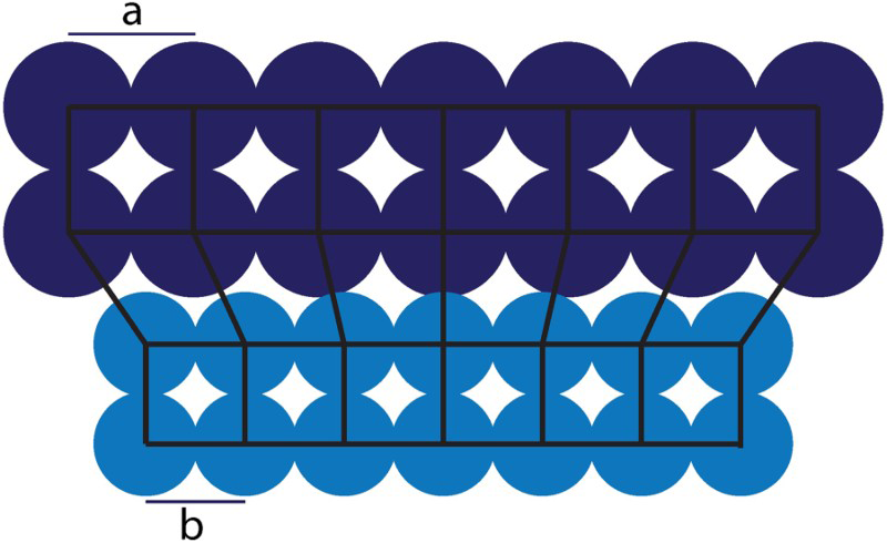
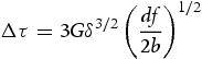
Evidently, a key parameter in determining the coherency strengthening effect is the lattice misfit (δ) between the γ and  phases. The general equation of the lattice misfit of an alloy is given as
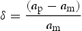
 and
and  are the lattice parameters of the matrix and precipitate phase, respectively.
For superalloys, commonly the lattice misfit is defined as
 and
and  are the lattice parameters of the
  and γ phase, respectively [2,29–32]. Equation (2) is equivalent to Equation (1) but with respect to an average lattice parameter of
  and γ.
In calculating the misfit, a distinction must be made between the constrained and unconstrained lattice parameters. The constrained value is that measured in the two-phase material, where the lattice parameters of each phase are forced to be more similar in the vicinity of the interface, to maintain coherency. In positively misfitting alloys, the lattice parameter of the precipitate phase is larger than that of the matrix, and is therefore forced to decrease. Lattice parameters of each phase measured in their single phase material, being unaffected by a neighbouring phase, are termed unconstrained. In contrast to the constrained lattice parameter, this is a fundamental parameter which does not depend on the size or morphology of the precipitate, nor the interface orientation with respect to the matrix. The use of constrained or unconstrained parameters should therefore be clarified in coherency strengthening models in the literature.
Preuss et al. [25] studied unimodal particle size distributions, and concluded that lattice misfit is independent of particle size. However, this could be due to the similar composition of the  within the narrow size distribution studied. As compositions differ between primary, secondary and tertiary particles [33–35], this conclusion is unlikely to hold across these cases. However, experimental measurements of the constrained lattice parameters of primary, secondary and tertiary
  are notably absent from the literature.
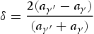
Many modern commercial Ni-based superalloys are designed to have a negative misfit between the γ and The directions of resultant stresses (indicated by arrows) caused by a tensile stress applied to a negatively misfitting alloy [2]. Reproduced with permission from Cambridge University Press. phases [2]. By definition, negatively misfitting precipitates must be under a tensile stress to maintain coherency with the matrix when constrained. Equivalently, the matrix phase must be under a compressive load (Figure 7). This reduces the drive for dislocation motion in the softer γ channels, thereby increasing strength.
However, Mughrabi [30] argued that a positive misfit (as defined by Equation (2)) would result in increased strength at high temperatures, and would be beneficial in terms of creep and fatigue resistance, although it was acknowledged that further experiments and modelling are required to confirm this. Using 3D discrete dislocation dynamics simulations, Gao et al. [29] also found that very small, positive misfits are preferable for increased resistance to deformation when under tensile loading conditions along [001], although the role of temperature was not included in this study.
The misfit is generally designed to be small ( ) [30], to minimise coarsening at high temperatures [2]. However, Zhang et al. [36] concluded that bigger misfits give superior mechanical properties (lower creep rate) because this requires more interfacial dislocations, blocking the movement of further dislocations that would shear the precipitates. In the same study, it was found that the mechanism of dislocation motion at high temperature (1100
 C) differed in two superalloys (TMS-75(+Ru) and TMS-138, with small (
 ) and large (
 ) lattice misfits, respectively). In the low misfit alloy, dislocations climb around the
  precipitates, whereas in the large misfit case, cross-slip occurs.
Evidently, there is a significant lack of consensus as to the role of coherency strain in these alloys, and the associated optimum sign and magnitude of the lattice misfit. Difficulties arise from the lack of distinction in coherency models between constrained and unconstrained lattice misfits, and the effect of a multimodal particle size distribution with associated compositional differences. It should be noted that the effect of temperature is an added complication.
Grain boundary strengthening
Perhaps the most comprehensively studied strengthening effect in superalloys, the presence of grain boundaries also serves to increase the strength of polycrystalline materials. The motion of dislocations is impeded by the presence of these boundaries, therefore when present, larger stresses are required to cause plastic deformation of the material [7]. The effect of grain boundaries on strength is well described, and the established model is detailed in Section 3.4.
Strengthening models
Solid solution strengthening
The γ phase
Solid solution strengthening of the γ matrix phase is commonly included in strengthening models in the literature [7,17,19,20,37,38], and has been determined to give an increment of around 100 MPa to the yield strength of IN100 [7]. In general, the solid solution strengthening effect can either be modelled by defining the solute atoms as obstacles that pin dislocations, or in contrast, by describing low energy positions in which each dislocation ideally lies [38–40]. In the latter, the presence of solute atoms augments the naturally occurring variable-energy landscape within a crystal lattice.
The presence of discrete solute atoms acting as obstacles to dislocation motion within the disordered γ matrix phase gives rise to strengthening by two factors; the difference in atomic size and the difference in shear modulus of the solute and matrix atoms. By modelling the interaction between a solute atom and a screw dislocation, Fleischer found that the modulus effect is the most significant [17].
However, using a statistical theory, Labusch [37] subsequently reached an alternative result which was corroborated by experimental data. The main difference between the two theories is the description of the dislocation flexibility. Additionally, Fleischer used an average value of the force of interaction of individual solute atoms on a dislocation, whereas Labusch considered a mean field distribution of multiple obstacles. The two studies do produce very similar results, however. The stress increment ( ) caused by a solute atom is calculated by Fleischer [17] to be
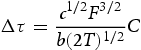
The exponent of  determined by Fleischer [17] arises from the assumption of low obstacle density, meaning that a dislocation does not immediately encounter another obstacle after overcoming one initially. In contrast, an exponent of
  emerges from the statistical theory of Labusch [37], when solving the derived equations in the asymptotic limit of low solute content or strong dislocation-solute interactions.
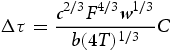
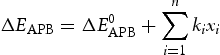
These models were subsequently extended to account for the presence of multiple, different solute atoms by Gypen and Deruyttere [41]. To determine the overall extent of solid solution strengthening using this model, the contribution of each individual element (i) to the yield strength (τ) is calculated and then summed
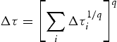
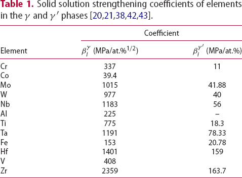
 ). Mishima [20] used compression testing of Ni containing small ternary additions of other elements to determine experimentally the increase in the strength of FCC Ni by solid solution strengthening. Using the data of Mishima [20] and other authors [38,42,43], the value of
  for each individual element studied can be determined. This constant is dependent on both the atomic radius and the elastic modulus of the alloying element. Values for
  are given in Table 1, but it should be noted that the units for this constant differ, depending on the exponent q.
 (MPa/at.%1/2)
 (MPa/at.%)
Subsequent authors [19,44] used the value of  proposed by Labusch [37] for the exponent q, as this was deemed to fit better to experimental data for superalloys. It therefore follows that each element in the γ matrix phase (i) provides a contribution of
  to alloy strength, given by
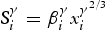
 is the concentration of element i in the γ phase, and
  is the solid solution strengthening coefficient specific to element i (with units of MPa/at.%2/3).
Using this value of  in Equation (5) then enables the calculation of the total strength arising from solid solution in the γ phase
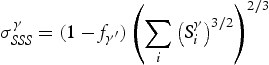
 is the volume fraction of the
  phase.
The  phase
phase
The presence of alloying elements in the ordered  phase has also been shown experimentally to give rise to solid solution strengthening [7,21,45–47], however, it is rarely included in strengthening models in the literature [19,44].
In the case of the  phase, a variation of Equation (6) can be used to determine the strengthening increment associated with each alloying addition (
 ). However, for this phase, the strength has been shown, through fitting to experimental data, to vary linearly with concentration (q=1) [21,47], in contrast to the 2/3 exponent (q) for the matrix γ phase. This gives
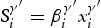
 is the concentration of element i in the
  phase, and
  is the solid solution strengthening coefficient specific to element i in the
  phase. Values for
  are given in Table 1.
The different strengthening increments of the γ and  phases (Equations (6) and (8)) arise due to the ordered nature of the
  phase. In addition to the local lattice distortion and local modulus variations caused by the presence of a misfitting element in the lattice, the ordered nature of the
  lattice means that variations in atomic bonding also exist, depending on which sub-lattice site the added element resides.
As for the γ phase, the total solid solution strengthening effect of the  phase is found by summing the individual contributions of each element, following Equation (5), giving
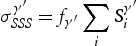
 precipitates is likely to differ [33,48] and therefore the extent of solid solution strengthening in each will also differ.
Precipitation strengthening
Precipitate shear
The initial models to be proposed for precipitation strengthening involved individual precipitates simplified to point objects distributed at random on a particular glide plane, and the dislocation modelled by its line tension,  [49]. In these models, the yield stress of the material was taken to be the minimum applied shear stress that enabled the dislocation to traverse the whole glide plane [50].
For a dislocation to move through an array of point obstacles, randomly distributed on the glide plane, Brown and Ham defined the critical shear stress,  , required as
 ),
),  [7].
[7].
A force balance is all that fundamentally is required to model the strengthening arising from the presence of ordered precipitates in superalloys. The contributing factors are the external force on the dislocation, the force of repulsion between the two partial dislocations of the pair, and the force from the APB, which acts in opposite senses for the leading and trailing dislocations. This results in two equations – for the leading and trailing dislocation, respectively [19]


 is the applied shear stress,
  and
and  are the lengths of the leading and trailing dislocations, respectively, that drive cutting,
  is the force of the dislocation pair per unit length and
  and
and  are the segment lengths of the leading and trailing dislocations, respectively, that are cutting the precipitates.
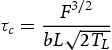
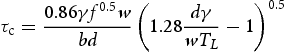
However, in reality the obstacles are not infinitely small, so a value for the precipitate spacing, L is required. Kozar [7] related the spacing between finite, spherical particles to the volume fraction, f, and the average planar diameter,  by
by
An improvement to these original models resulted from both modelling the precipitates as having finite shape and size, and defining the mechanism of interaction between the precipitate and dislocation [24]. This enabled the different regimes of dislocation motion – weak pair coupling, strong pair coupling and Orowan looping – to be defined and modelled separately.
Brown and Ham [50] concluded that the shear stress required for strong particles is defined by the equation
 is considered, and only low volume fractions of
  are applicable.
In contrast, Reppich [27,52] defined the shear stress of material containing strong precipitates as
 volume fractions are applicable, and the empirical parameter w is required to account for uncertainties and other strengthening mechanisms.
These equations differ to those of a separate investigation by Kozar et al. [7], where strong and weak pair coupling were described by Equations (18) and (19), respectively, even though this model was also based upon the original equation of Brown and Ham (Equation (10)), but edited for superalloys by taking into account finite precipitate size and the presence of two dislocations linked by an APBE

 is the spacing between particles (after taking into account finite size) and
  is the precipitate spacing in the case of strong pair coupling.
  is different to
  since two dislocations are present in the same precipitate, and at the critical configuration for precipitate cutting, the length of the dislocation present within the precipitate is not equal to the precipitate diameter
  of Equation (13). This model is an improvement, since high volume fractions of
  may be considered, however, a constant interparticle spacing is assumed, which is not applicable to the case of multimodal particle size distributions, common in superalloys.
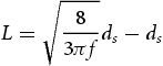
Evidently, a value for the precipitate spacing is required for these models, but this is also inconsistently defined in the literature. Hüther and Reppich [27] describe the particle spacing ( ) as
) as  , based on the average planar spacing in a square lattice. Alternatively, Gerold and Haberkorn [4] obtained expressions for L which vary depending on the flexibility of the dislocation line

However, it is unproductive to emphasise the precipitate spacing while ignoring the distribution of the precipitates themselves – the precipitate spacing is evidently affected by their distribution on the dislocation glide plane.
Some authors use a square lattice through which the dislocation pairs propagate, for which the obstacle spacing approximates to  with N as the number of obstacles per unit area [3,8,19]. This is not equivalent to other characteristic obstacle spacings, such as the average planar spacing (
 ) or the average obstacle spacing along the dislocation line itself [3]. Another option is to use a statistical, random distribution of particles of random size, which is said to increase the accuracy of results [53,54].
Foreman and Makin [49] showed that the calculated value for  differs depending on the shape of the array modelled. For strong obstacles (those present in the strong pair coupling regime), experimental data were predicted well by approximating a regular array of obstacles. Although modelling the dislocation as lying along the length of the square array was shown to give values for
  that were too large, when defining L as the average of the square and diagonal lengths (Equation (23)), the experimental data were fitted well for strong obstacles
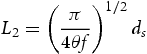
 ) is shown to fit the experimental data well [49]. Friedel statistics describe the movement of dislocations through an array of obstacles by the sequential ‘unzipping’ and then bowing out from each encountered precipitate [3]
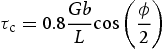
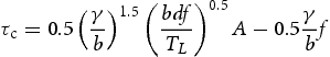
Using Equation (24) for L, and the same force balance given in Equation (11), Raynor and Silcock [8] reached an expression for the increase in shear stress caused by precipitation hardening:
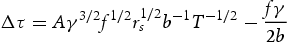
 being the mean planar radius of the precipitates and A a numerical factor. An earlier study [26] reached a different conclusion (Equation (26)), although there are similarities in the first term

 phase can reach 70%, and where the precipitate size distribution may be tri-modal. Even within a distribution of secondary or tertiary
  precipitates, there is a range of particle sizes, which is not taken into account in these equations but will affect the yield strength.
In fact, in contrast to these classical models, it has been shown that weak and strong pair coupling models are not reproduced closely by the experiment, in particular for high volume fraction alloys [19]. An added complication is the transitional region between weak and strong pair coupling. Classical models consider these two regions separately, and assume a smooth convergence between the two regimes. In reality, the two cannot be smoothly joined because they have very disparate arrangements. For example in weak pair coupling, the leading dislocation curves out around the precipitates. In contrast, in strong pair coupling the leading dislocation is straight. Clearly, a transitional region must occur between the two separate regimes. This inconsistency is paramount in Ni-based superalloys, since the size of the precipitates is often within this transitional region.
Galindo-Nava et al. [19] have attempted to solve these inconsistencies by unifying the weak and strong coupling regimes. They defined a transitional region where the leading dislocation has just exited the precipitate while the trailing dislocation is just about to enter the precipitate (Figure (8)). Schematic showing the configuration of the dislocation pair in the transitional region between strong and weak pair coupling [19]. Reproduced with permission from Elsevier.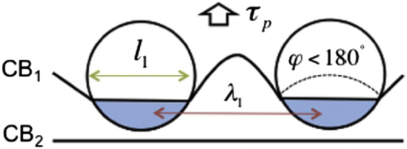
A further lack of consensus exists regarding what feature of the  phase gives rise to the strengthening increase – volume fraction or number density. Most commonly in the literature, the volume fraction is used [7,8,52,55]. However, Galindo-Nava et al. [19] use the number density. This follows from the fact that it is the γ /
  interface that provides the initial barrier to dislocation motion (giving rise to a yield strength). Of course after initial yielding, the motion of dislocations through the
  precipitates also imparts strengthening, therefore at this point,
  volume fraction may be the more appropriate variable.
Further inconsistencies in the literature arise from the shape of the precipitates and their size distributions. This is significant in the case of superalloys, since precipitate morphologies commonly vary from spherical to cuboidal to octo-dendritic [56] (Figure 9). Some models apply purely to spherical particles [57] while others consider different morphologies [53,58,59]. The precipitate morphology has been shown by discrete dislocation simulations to affect the strength of Ni-based superalloys [24]. It was found that spherical precipitates are stronger than cubic precipitates of size 100 nm and APBE 320 mJ m−2, but as precipitate size and APBE decrease, this has less of an effect. Kozar et al. [7] found that their yield strength model fitted well to the experimental data for a subsolvus IN100 alloy. However, the yield strength for the supersolvus IN100 alloy was overpredicted. This is evidence for the requirement of a full description of the particle size distributions for yield strength modelling. Micrographs showing characteristic morphologies of  precipitates in model Ni–Al–Ti–Cr–Mo alloys, which can vary from spherical to cuboidal to octo-dendritic.
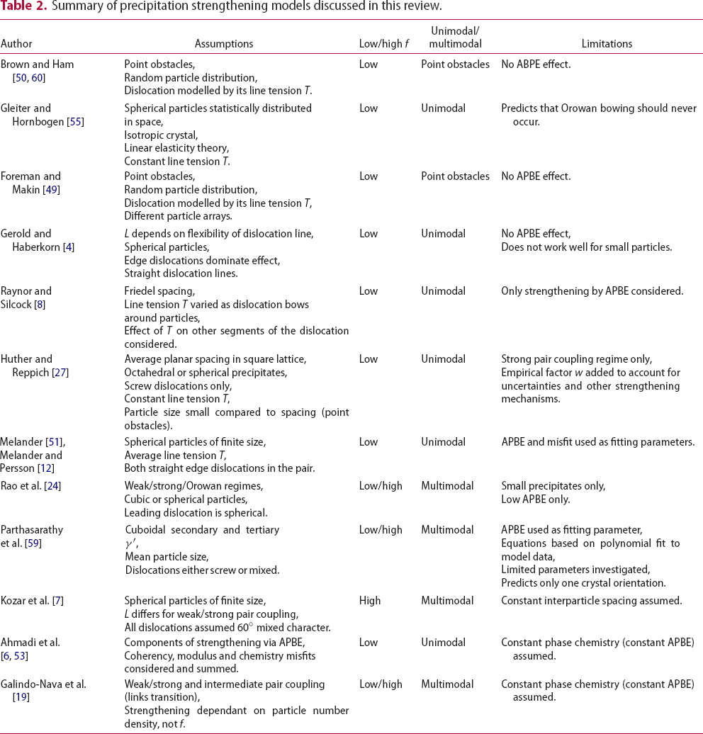
Summary of precipitation strengthening models discussed in this review.
Equations (11) and (12) and the subsequent equations presented in this section were defined using the APBE as the only factor to impede dislocation motion, so precipitation (order) hardening is the only strengthening mechanism considered. The APBE therefore features heavily in these equations, and its value must be determined.
Anti-phase boundary energy (APBE)
The shearing of precipitates by dislocation pairs gives rise to an anti-phase region between the two dislocations. Within this region the ordering is disrupted, with Al atoms sitting on the Ni sites (for example), and vice versa. The ensuing energy increase caused by these unfavourable nearest-neighbour atoms means that shearing of dislocations through ordered precipitates is less favourable than through a disordered phase. Accordingly, since more energy must be inputted to cause this precipitate shear, the strength of the alloy is increased.
It is clear then that the magnitude of the APBE produced must be linked to the overall strengthening effect imparted by the ordered nature of the  phase. The APBE may be determined experimentally using the separation distance between the dislocations in a pair [61,62], but this is not trivial, and is subject to much uncertainty. Modelling therefore is a useful alternative.
The original models for APBE in FCC structures involved a study of the bonds broken and reformed across the boundary, taking into account nearest-neighbour bonds only [63–66]. However, it was later shown that a minimum of second-order nearest-neighbour interactions must be accounted for in calculation of the APBE of ordered FCC structures [67], although further interactions improve the accuracy of the model [68,69].
A thorough model for the APBE was proposed by Inden et al. for the L and L
and L structures of ordered FCC alloys, in particular Ni
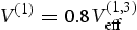
 Fe [70]. The model describes the APBE as a function of composition. Correlation functions were proposed to simplify the modelling of APBEs, and interactions up to the fourth nearest neighbour were included. This model was commonly used by subsequent authors [71–73]. In this study, the APBE on the {111} planes (
 ), assuming perfect ordering, is determined using the equation
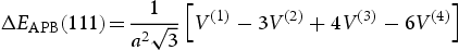
 to
to  are the nearest-neighbour interaction energies for the first to fourth nearest-neighbour atoms.
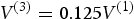
The terms  to
to  are obtained from the internal enthalpy of the γ phase (
 ) and the ordering enthalpy (
 ) using the following equations:
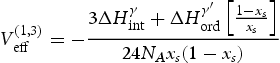
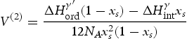
 is Avogadro's constant and
  is the concentration of the solute element in the ordered phase.
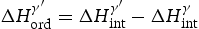
Crudden et al. [71] have more recently used the same model for the APBE in Ni-based superalloys, using equilibrium precipitation software (ThermoCalc) to determine the internal enthalpies of γ and  . The difference between these values, assuming identical compositions of γ and
  , gives the enthalpy of ordering of the
 ) linearly linking the solute content (
 ) to the APBE. The effect of each element is then simply summed to give the overall APBE in an alloy of n different elements
 is the APBE of pure Ni
 Al. This method was deemed to be more reliable than the original theory of Inden [70] through closer fit to experimental data. However, this method was only applicable to low solute concentrations. Experimentally, the APBE of the {111} planes in stoichiometric Ni
 Al has been measured to be
  mJ m−2[61] and
  mJ m−2 [78].
Other methods of modelling the APBE computationally do exist, but are not detailed within this review [79–81].
It should be noted that APBE is very closely linked to the precipitate composition, and this has been shown to vary with precipitate size [33,82]. Therefore, the magnitude of the APBE will differ between precipitates, in particular, between precipitates of different size distributions (secondary and tertiary  ). This could result in large differences in the order strengthening effect of the secondary and tertiary
  , thereby affecting the predicted yield strength. Such compositional variations must be carefully considered in yield strength models, although currently this is not seen in the literature.
Orowan bowing
At large particle size, Rao et al. [24] observed a transition to Orowan looping, with a corresponding decrease in CRSS as precipitate size increased. This is consistent with classical theories in the literature for strengthening by precipitates [83], but is in contrast to Preuss et al. [25] who stated that Orowan looping is not commonly seen in polycrystalline Ni-based superalloys. A number of reasons were given for this conclusion, including the fact that superalloys generally do not contain large precipitates, the low lattice misfit in these alloys, or the bi- or tri-modal size distribution of precipitates.
Orowan looping (or bowing) around precipitates occurs when the stress reaches a value given by [50]

Coherency strengthening
Many equations and models exist with the aim of describing the effect of coherency strengthening, but different assumptions are used and the fit to experimental data is poor. However, the one consistent observation is the fact that coherency strengthening is dependent on the magnitude of the lattice misfit, irrespective of its sign.
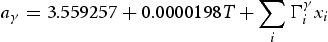
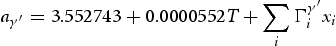
To quantify misfit, values for the lattice parameters of each phase are required. These can be deduced experimentally or by using equilibrium phase modelling (ThermoCalc). Alternatively, in the alloys-by-design model [90], Reed et al. defined equations for the lattice parameters (in units of Å) of the γ and  phases as
 and
and  are Vegard coefficients, x is the mole fraction, and T is the temperature (kelvin). The misfit is then calculated using Equation (2). Equations (35) and (36) were developed by fitting experimental data for the single-crystal alloy CMSX-4 at 900
 C [90]. As such, these equations cannot be assumed to be valid for any other alloy or temperature.
It has been concluded that the yield strength of several austenitic steels was not affected by misfits between 0 and 0.4%[8]. In contrast, other studies have concluded that coherency strain in  strengthened alloys does have a significant effect on yield strength, for misfits between 0.2 and 0.8%[4,9]. In fact, an increase in lattice misfit from 0.2 to 0.8% was seen to double the hardness of ternary Ni–Al–X alloys. Conversely, at times the effect of coherency is completely ignored [7].
Alternatively, Decker [5] states that coherency strengthening is only important in certain alloys, due to the effects of certain elements. For example, it is stated that Mo would reduce the coherency strain because it preferentially partitions to the γ phase and (as the atomic radius of Mo is large) therefore increases the lattice parameter of the matrix phase. Hence, Decker concludes that alloys strengthened by the coherency effect would have no Mo content. However, this conclusion cannot be drawn consistently, as in negatively misfitting alloys (where the γ phase has the larger lattice parameter), adding more Mo would actually increase the misfit.
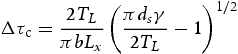
Oblak et al. [91,92] studied the effect of  precipitates in alloy 718. It was found that the effect on CRSS (
 ) due to coherency strains from
  precipitates on {100} is approximately given by
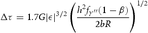
where ε is the tetragonal misfit (i.e. of type  ), β is the fraction of precipitates with c-axis perpendicular to the Burgers vector and
  is the volume fraction of the
  phase. h and R are the half-thickness and radius of the precipitates [91]. It was concluded that coherency strengthening is the major source of strength in superalloys containing D
 phase
phase  precipitates. Order strengthening was also considered but was found to be less significant. However, it was stated that in traditional
  strengthened alloys, order, not coherency hardening, is the primary strengthening mechanism. It is not clear why the conclusions drawn for coherency strengthening in the
  strengthened alloy 718 cannot also be applied to
  strengthened alloys. Besides the tetragonal shape of the precipitates in the former, there is no other significant difference. Therefore, this study could be more evidence for the importance of coherency strengthening.
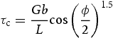
Gerold and Haberkorn [4] also attempted to model the effect of coherency strain, which is taken to be the dominant strengthening mechanism in alloys with spherical, coherent precipitates. They derived the equation
Conversely, Mott and Nabarro [93] described coherency strain without considering the effect of dislocations at all by simply defining the hydrostatic pressure caused by a misfitting volume.
Evidently, a systematic and fundamental study of the role of coherency strengthening in Ni-based superalloys is required to enable the design of new alloys with superior mechanical properties. A detailed understanding of the variation of misfit with temperature is also lacking in the literature. This is consequential since these materials exist at high temperatures during service, so it is the high-temperature misfit that influences the mechanical properties in service.
Grain boundary strengthening
It is commonly established that the extent of grain boundary strengthening is described well by the Hall–Petch relationship [94,95]:

 is a constant that has been determined to be 750 MPa
  for superalloys [7,19].
For the case of superalloys, however, it must be noted that there are two components to grain boundary strengthening; in addition to strengthening from the grain boundaries in the γ matrix phase, the large, primary  precipitates also contribute. Equation (39) should be modified to account for the finite volume of material applicable to grain boundary strengthening – that is, regions of γ matrix phase, and regions of neighbouring primary
  precipitates. This can be simply done by multiplying by a prefactor,
  , where f is the total fraction of the material that is either γ matrix or primary
  precipitate phase. The factor
  has been estimated experimentally as the fraction of primary
  precipitates that are neighbouring to another primary
  precipitate [7].
The extent of grain boundary strengthening by primary  precipitates has been found to give rise to an increment of around 50 MPa in the yield strength of subsolvus IN100, compared to the supersolvus variant [7]. However, since other strengthening mechanisms also vary between these alloys, this increase is not reproduced in the overall yield strength. The extent of grain boundary strengthening by the γ phase was more significant, reaching approximately 300 MPa in subsolvus IN100.
Total yield strength
Evidently, there are many underlying mechanisms that add to the appreciable yield strength of Ni-based superalloys. However, there is a lack of consensus in the literature as to how these mechanisms combine to give an overall, measurable yield strength. Some authors conclude that a single mechanism is the major cause of strengthening in Ni-based superalloys [3,14,72,91]. However, many authors combine some, or all, of the various mechanisms to determine the overall yield strength [4,7,8,19,96]. For example, Singhal and Martin [14] take into account precipitation and coherency strengthening, by adding together the equations given by Gleiter and Hornbogen [55] and Gerold and Haberkorn [4] (Equation (38)) for APBE and coherency strengthening, respectively. This was concluded to fit with the experimental data.
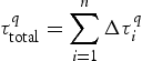
In general, it may be agreed that the total yield strength is a sum of the individual strengthening mechanisms
Summary and outlook
It is clear that there are currently many issues with modelling the strength of Ni-based superalloys. There is a significant lack of agreement on which mechanisms are dominant, or even which are operative. The details of how to model precipitation and coherency strengthening are particularly varied in the literature, and there is no unanimously agreed standard for modelling any of the strengthening mechanisms, or how to combine them to give an overall yield strength. The individual shortcomings that limit each model are discussed in this review, demonstrating that there is no single model that addresses all the issues found in Ni-based superalloys. The effect of temperature adds another complication.
It has been suggested by Kozar et al. [7] that the variation of the particular active strengthening mechanism could account for some of this difficulty. For example, cross-slip-induced hardening is said to occur in both primary and secondary  precipitates, whereas strong pair coupling occurs in the secondary and tertiary particles. In contrast, solid solution strengthening and hardening from grain boundaries are most important in the γ matrix. Many of the models detailed in this review do not ever consider the concurrent operation of multiple modes of dislocation propagation (for example, bowing and strong pair coupling occurring simultaneously), but simply consider one at a time. This is non-physical, since precipitates of different sizes exist in real microstructures (or at least the apparent precipitate size is different depending on the slip plane of the dislocation), and therefore this must clearly affect the resulting yield strength. Parthasarathy et al. [59] go as far as noting that precipitate cutting can actually be aided by bowing of the dislocation slightly around the precipitate beforehand. This lowers the critical stress required for cutting, thereby affecting the modelled yield strengths.
A comprehensive understanding of the extent of the many concurrent strengthening mechanisms operative in Ni-based superalloys is essential to enable the design of superior alloys for present and future applications. If these mechanisms are fully understood, alloys can be designed with microstructures optimised to the strengthening mechanisms that are known to be occurring. An attempt has been made to use yield strength modelling to design an optimised new Ni-based superalloy [72], however, it was found that although the ‘ideal’ alloy showed increased strength, it lacked ductility. In that study, only strengthening via precipitates was taken into account. Clearly, multiple mechanical properties must be taken into account to design optimised superalloys. In the end, this will overcome the current limitation of aircraft engine design – the materials.
Footnotes
Acknowledgments
The author would like to thank Dr H. J. Stone and Dr E. I. Galindo-Nava for feedback.
Disclosure statement
No potential conflict of interest was reported by the author.
References
 precipitating alloys
 hardened nickel alloys
 hardened nickel-base alloy
 (ordered Ni
 Ti) precipitates
 Nickel-base superalloys
 Al with ternary addition of transition metal elements
 hardened superalloy Nimonic PE16 in high-voltage electron microscopes
 lattice misfit in superalloys—with special reference to the new
  -hardened cobalt-base superalloys
 strengthened Co-base superalloys in the Co-W-Al-Ti quaternary system
 interface width in a commercial nickel base superalloy studied by three-dimensional atom probe tomography
 Al by alloying with zirconium
 Al alloyed with iron additions
 precipitating nickel-base alloys—II. Experiments
 Al (
Al ( )
) Al by ternary additions
 Al
Al ) precipitates in an advanced nickel-based superalloy
 precipitating Ni-base alloys. Theoretical concept
 precipitates in nickel-base superalloys
 precipitate dispersion of polycrystals of a nickel-base superalloy
 Al
Al Al
Al and AuCu type superlattices
 Al: generalized peierls model in combination with ab initio electron theory
 , Ni
, Ni Al, Ni
 Ge and Fe
 Ge: Peierls-Nabarro analysis starting from ab-initio GSF energetics calculations
 Al
Al Al
Al and DO
 compounds
 -phases of the Ni-Al system
 ) precipitates formed at different cooling rates in an advanced Ni-based superalloy
 O
O particulate-reinforced aluminium matrix composites
 precipitates