
Abstract
The superimposition of time-dependent damage on fatigue, otherwise, known as creep-fatigue interaction (CFI), significantly affect the fatigue life of power plant boiler components. IN740H is a candidate material for advanced ultra-supercritical (A-USC) boilers components. The creep-fatigue interaction of alloy IN740H was studied at 760°C, by conducting low cycle fatigue (LCF) at a strain amplitude (Δϵt/2) value of 0.4% and holding at peak strain in tension, compression and both for 0, 1, 5, 10 and 30 min duration. Though hold time adversely affects fatigue life, tensile hold is the most damaging of all three hold modes. The reason behind maximum damage with tensile hold is grain boundary cavitations and coalescence of cavities leading to internal cracks formation at grain boundaries.
Introduction
The precipitation hardenable nickel base superalloy IN740H was recently developed for manufacturing pressure parts in A-USC boilers operating at 760°C steam temperature [1–3]. Structural components in power plant boilers experience thermal transients due to start-up and show-down operations and load fluctuations caused by varying demand of electricity [4]. Due to fluctuating temperature and pressure in the boiler tubes and other thick section components, cyclic thermal stresses are developed and low cycle fatigue along with creep eventually becomes an important failure mode [5]. In many instances, failures of boiler components have revealed signs of damage, which is attributed to creep-fatigue interactions [6,7]. Gemmill [6] has discussed that failures due to time dependent plasticity were observed in components like boiler drums, superheater tubes and headers, steam pipes etc of steam power plants. Therefore, efforts are being made to design the boiler components against creep damage superimposed by fatigue. The interactions of these two damage modes complicate the subject immensely and understanding in this regard is scarce. For instance, fatigue damage arises due to the frequent start-ups and shut-downs that produce surfaces cracks and creep damage occurs during dwell time which is manifested by creep voids at the grain boundaries and thus accelerates the damage [8]. Therefore, it is of great importance for the design, life prediction and long term operation of hot section components to have a fundamental understanding of combined creep-fatigue deformation. It is simulated at the laboratory scale by conducting high temperature LCF tests employing different strain rates or with the incorporation of a hold time at peak strain. In an earlier study from this group where LCF behaviour of alloy IN740H was studied at 760°C employing strain rates ( ) of 1 × 10⁻², 1 × 10⁻³, 1 × 10⁻⁴ s−1, it was established that the creep effect during tests at a lower strain rate, i.e. 1 × 10⁻⁴ s−1 lowers the fatigue life of alloy IN740H significantly [3]. Creep effects manifested in [3] as intergranular separation of grain boundaries due to ingress of oxygen during slow strain rate fatigue tests. In the present research, it is attempted to understand the damage modes by comparing the mechanical responses and microstructural degradation by conducting a fully unbalanced condition (tensile and compressive holds) and fully reversed balanced loading conditions (both hold). The fatigue tests were carried at
  of 1 × 10⁻³ s−1 with 0, 1, 5, 10 and 30 min hold duration at a strain amplitude (Δϵt/2) value of 0.4% for understanding the time dependent damage effect on fatigue behaviour of alloy IN740H. The thermal fluctuations in actual operations are well below the Δϵt/2 chosen for the study and the hold durations were chosen based on practicality of testing in laboratory conditions. The effect of mechanical responses and how it influenced the fatigue life from a normal fatigue was studied by performing the strain controlled hold cycle. An attempt is made to correlate the creep-fatigue interaction behaviour to microstructural damage by conducting extensive electron microscopic studies.
Experimental procedures
Chemical composition of the as-received alloy IN 740H in wt-%.

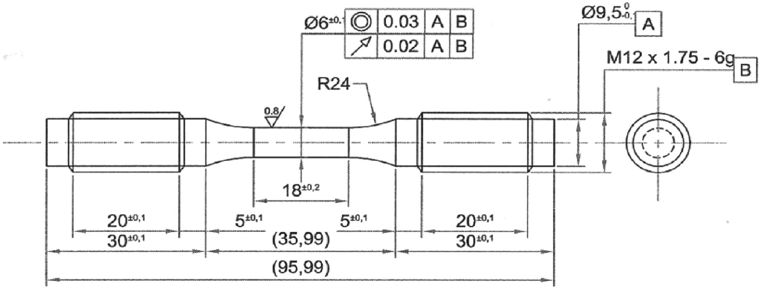
CFI tests were carried out under fully reversed total axial strain amplitude control mode by conducting a fully unbalanced condition (tensile and compressive holds) and fully reversed balanced loading conditions (both hold) at 760°C ± 2°C using a servo electric testing machine model INSTRON 8862. The tests were conducted at a nominal Dimensional drawing of a LCF test specimen used in the present study. of 1 × 10⁻³ s−1 at Δϵt/2 value of 0.4% with hold durations of 0, 1, 5, 10 and 30 min. Also fatigue tests without hold times at a Δϵt/2 value of 0.4% at different
  of 1 × 10⁻², 1 × 10⁻³ and 1 × 10⁻⁴ s−1 were conducted to compare and elucidate the effect of hold time on fatigue life. A dimensional drawing of the fatigue test specimen is given in Figure 1. The test temperature was controlled by a 3-zone PID temperature controller model Eurotherm maintaining a constant temperature within ± 2°C in all the three zones. The temperature on the specimen was measured with two Pt-13%Rh thermocouples tied to the gauge length portion of the specimen. Strain measurements were made using a high temperature extensometer with a gauge length of 12.5 mm and travel range of ± 20%. Cusping of the cyclic stress–strain hysteresis loop indicated crack initiation in the specimen within the gauge length. This was invariably associated with sudden load drop in the cyclic deformation curve and was considered as cycle to failure (Nf). For tests, where cyclic saturation was not observed, the hysteresis loops corresponding to mid-life (Nf/2) were used for calculation of the plastic strain and stress amplitudes at saturation.
Results of hold time fatigue tests at 760°C; Δϵt/2 = 0.4%, = 1 × 10⁻³s−1.
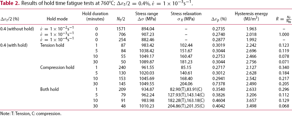

Note: T: Tension, C: compression.
Results
Microstructure
The microstructure of the as-received alloy consists of γ-austenitic grains and annealing twins as shown in the optical micrograph in Figure 2. The grain size measurements were done by analysing 10 images taken at 100X using the ImageJ software and the average grain size was found to be 110 µm. The SEM micrograph in [3] of the as-received alloy also reveals the necklace carbide structure along the grain boundary. The alloy IN740H is strengthened by γ′ and carbide precipitates. The γ′ precipitates in the as-received alloy are spherical in shape and of 10–20 nm and volume fraction of γ′ is ∼18% [3]. Discrete M23C6 carbides were observed at the austenitic grain boundaries and MC carbides were observed in the grain body as shown in the TEM micrographs in [3].
Optical micrograph showing the austenitic grains with annealing twins.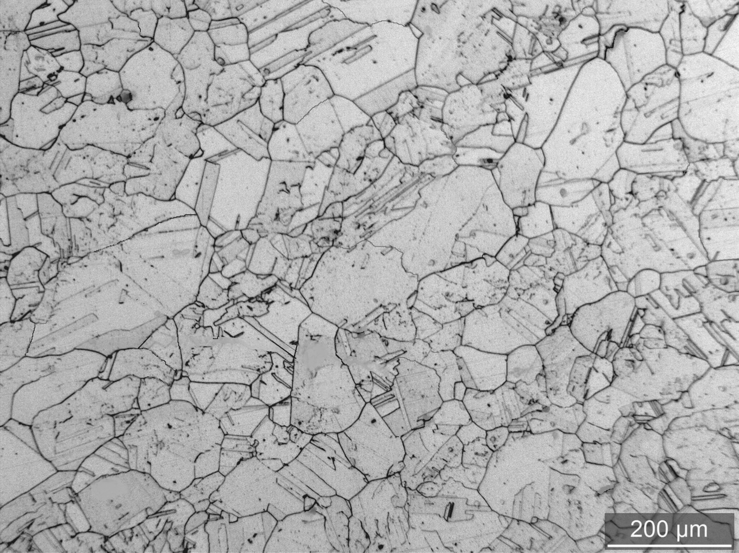
Cyclic deformation behaviour
Cyclic deformation curves were obtained by plotting the tensile peak stresses against the number of cycles. The cyclic deformation curves in tension hold shows almost a stable region for initial few cycles followed by softening till failure as shown in Figure 3(a). The initial few cycles of hardening was observed in case of compression hold and both hold followed by softening till failure as shown in Figure 3(b,c). It is observed that the deformation curves corresponding to fatigue tests with compression hold lie above the deformation curves of tension hold and both hold. It essentially means that the alloy requires more stress in tension to obtain the desired strain of 0.4%, when the fatigue test is conducted with hold at compression peak strain.
Effect of hold time on cyclic deformation behaviour of alloy IN740H at 760°C at Δϵt/2 = 0.4% in (a) tension hold, (b) compression hold and (c) both hold.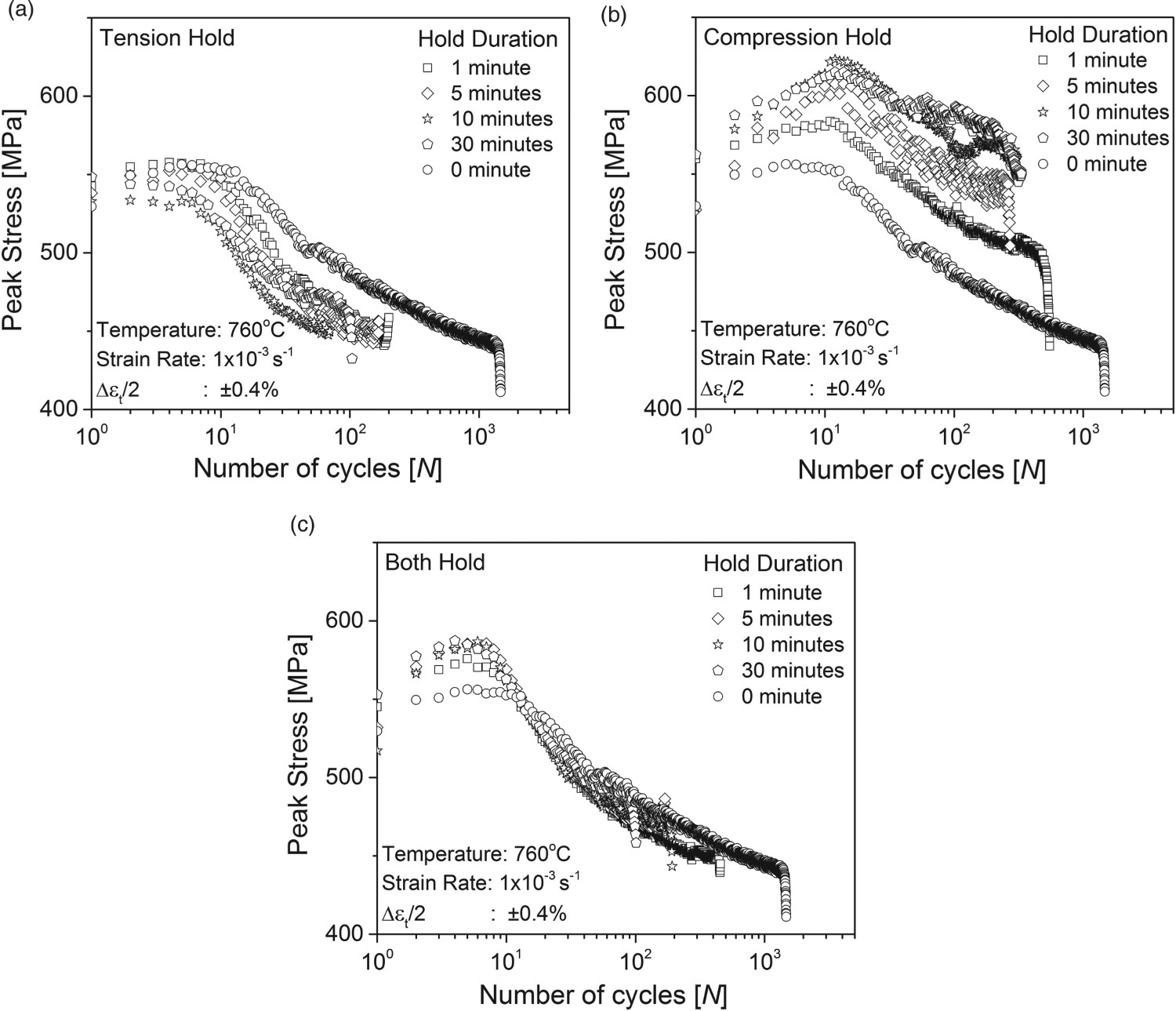
The hysteresis loops corresponding to the stable cycles of 0 min hold and hold time fatigue tests are shown in Figure 4. It is observed that hysteresis loops corresponding to fatigue tests with tension hold shift to the right and downwards with respect to hysteresis loops corresponding to 0 min hold fatigue test as shown in Figure 4(a). In similar way, the hysteresis loops corresponding to fatigue tests with compression hold shift left and upwards with respect to hysteresis loops corresponding to 0 min hold fatigue tests as shown in Figure 4(b). The magnitude of shift is observed to be proportional to the magnitude of the relaxed stress during the hold period. The hysteresis loops corresponding to both hold are observed to be symmetric about the origin and widen with increase in the hold time as can be seen from Figure 4(c).
Stabilised hysteresis loops corresponding to fatigue tests at 760°C and Δϵt/2 = 0.4% with different hold modes and durations: (a) tension hold, (b) compression hold and (c) both hold.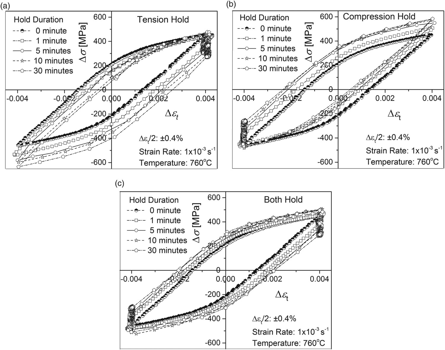
The mean stress developed during fatigue tests with different hold modes and durations are plotted and compared with 0 min hold fatigue, i.e. without hold time is shown in Figure 5. In 0 min hold fatigue slightly compressive mean stress of around −15 to −20 MPa was developed as shown in Figure 5. In tension hold compressive mean stress was developed and it increases with increase in hold duration reaching a value of about −80 MPa, when the hold duration is 30 min (ref. Figure 5(a)). In compression hold tensile mean stress was developed in the material and it increases with increase in hold duration reaching a value of about 60 MPa, when the hold duration is 30 min (ref. Figure 5(b)). The magnitude of mean stress developed during fatigue tests with compression hold is comparatively less than the magnitude of mean stress developed during fatigue tests with tension hold. The mean stress developed during fatigue tests with both hold is compressive in nature and lies close to the vicinity of mean stress developed during 0 min hold fatigue test as can be seen in Figure 5(c).
Mean stress developed during fatigue tests at 760°C at Δϵt/2 = 0.4% and hold in: (a) tension hold, (b) compression hold and (c) both hold.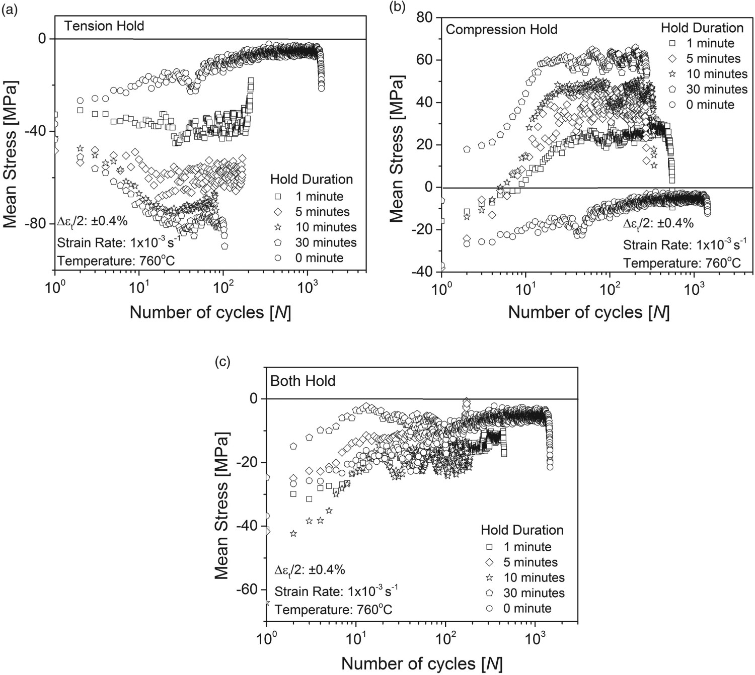
The influence of other variables like life reduction factor, fatigue life, plastic strain and hysteresis energy with hold duration is shown in Figure 6. The fatigue life reduction factor, R is defined as the ratio of Nf/Nfo, where Nf is the life recorded for a given strain rate/hold time test and Nfo is the reference life value for continuous cycling (i.e. with 0 hold min at 10−3 s−1). The plot between life reduction factor, R and cyclic duration of different fatigue tests conducted in the present investigation is shown in Figure 6(a). The R value is taken as 1 for the 0 min hold fatigue test at 760°C conducted employing strain rate of 1 × 10⁻³ s−1. Fatigue life decreases drastically with decrease in the strain rate. The reduction factor, R in case of fatigue tests with compression and tension hold changes marginally with increase in hold duration. In case of both hold the slope is steeper than the other two holds indicating that there is drastic change in fatigue life with increase in hold duration. A careful observation at the life reduction factor over a range of hold modes and hold durations reveals that the tension hold has the low life reduction factor values in comparison with compression and both hold.
Influence of other variables on creep-fatigue life with increase in cycle per time: (a) reduction factor, R (b) fatigue life, Nf (c) plastic strain, Δϵp and (d) hysteresis energy.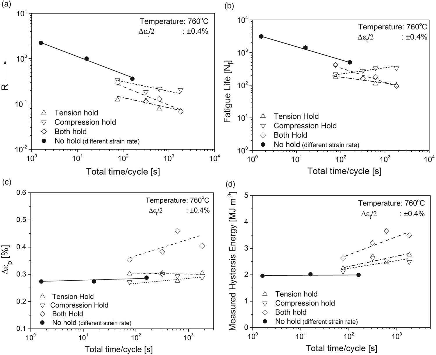
The fatigue life plotted against different loading conditions is shown in Figure 6(b). The fatigue life decreases with decrease in the strain rate and it was also observed that it decreases with increase in hold duration for tension and both hold. Except in case of compressive peak strain hold the fatigue life increases with increase in the hold time. In Figure 6(c) the plastic strain is plotted under different loading condition. There is a marginal increase in plastic strain with decrease in the strain rate. In LCF with hold time the plastic strain increases with increase in the hold time. It is observed that there is a drastic increase in plastic strain in specimens failed in both hold (balanced condition) and a marginal increase in the plastic strain in compression hold failed specimens. In tension hold marginal decrease in plastic strain was observed with increase in the hold time. So, there is a less plastic strain accumulation taking place in a tension hold cycle with increase in hold time and this may be one of the probable reasons for having less life in tension hold.
Figure 6(d) shows the measured hysteresis energy under different loading conditions. The hysteresis energy seems to be constant with decrease in the strain rate. In LCF with hold, marginal increase in the hysteresis energy is observed with increase in hold time in tension/compression peak strain hold while there is a drastic increase is observed in both hold. From Figure 4(c), it is seen that during the both hold the loop open up much more widely than in the other two hold modes as the stress relaxation take place in both compression and tension. As a result the hysteresis energy in both hold is higher than the other two hold modes.
Creep-fatigue interaction diagram
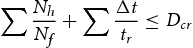
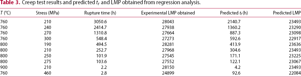
The mechanisms of deformation and eventual failure of alloys during hold time fatigue depend on various test and material parameters. Test parameters such as stress or strain rate, temperature, loading frequency and loading waveform are known to influence life resulting from creep fatigue interactions. The reported methods for the creep fatigue interaction life prediction include linear damage summation, frequency modified Manson-Coffin equation, frequency separation technique, strain range partition, strain energy partition, frequency modified damage function model, ductility exhaustion method, damage rate approach and linear or bi-linear damage summation rules [9]. Though many predictive models exist, linear or bi-linear damage summation rules are currently used in the ASME design codes for high temperature creep-fatigue life assessment because of its relative ease of application over wide range of conditions and the huge availability of application data [10]. The calculation of creep fraction is done either by ductility exhaustion or time fraction method. In the present study, time fraction method is used.
Creep test results and predicted tr and LMP obtained from regression analysis.
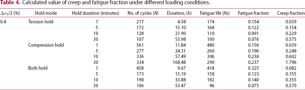
The calculated value of creep and fatigue fraction under different loading conditions is summarised in Table 4. These results are plotted in the creep-fatigue interaction diagram shown in Figure 7. Creep-fatigue interaction diagram shows the cumulative creep versus fatigue damage of alloy IN740H tested at 760°C and Δϵt/2 = 0.4% in comparison with the bi-linear damage summation curve for alloy 617 draft code case [15] and alloy 800H ASME code case N-47 and RCC-MRx [16]. The linear summation rule, where the total allowable critical creep-fatigue damage, Dcr, equal to 1 is also plotted in this graph. It is observed that damage is creep dominated and is above the alloy 800H (ASME N-47) and alloy 617 draft code case line. Except in case of 1 min dwell time of tension hold and compression hold, it is found to be fatigue dominated and lies below the alloy 617 draft code case line.
Creep-fatigue interaction diagram showing the cumulative creep versus fatigue damage results of alloy 740H tested at 760°C and Δϵt/2 = 0.4%. Calculated value of creep and fatigue fraction under different loading conditions.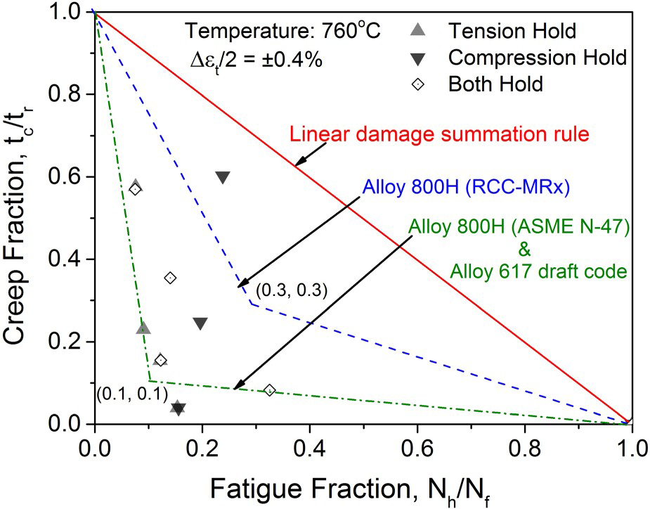
Fracture mechanism
The fracture surfaces of fatigue failure specimens were examined with an SEM. A few representative fractographs revealing features of damage initiation sites in fatigue failure specimens with hold of 1 and 5 min duration are shown in Figure 8. Predominant intergranular crack initiations were observed in fatigue failure specimen with tensile hold of 1 min duration as shown in Figure 8(a). However, the damage initiation was transgranular in fatigue failure specimens with compressive hold and both hold of 1 min duration as shown in Figure 8(c,e). However, intergranular crack initiations were observed in fatigue failure specimen with hold duration of 5 min in all three hold modes as shown in Figure 8(b,d,f). This indicates that crack initiation changes from transgranular to intergranular in compression hold and both hold with increase in the hold duration whereas crack initiation tends to be intergranular in tensile hold.
SEM images of fracture surfaces of fatigue failure specimens at 760°C with hold durations of 1 and 5 min (a,b) tension hold; (c,d) compression hold; (e,f) both hold.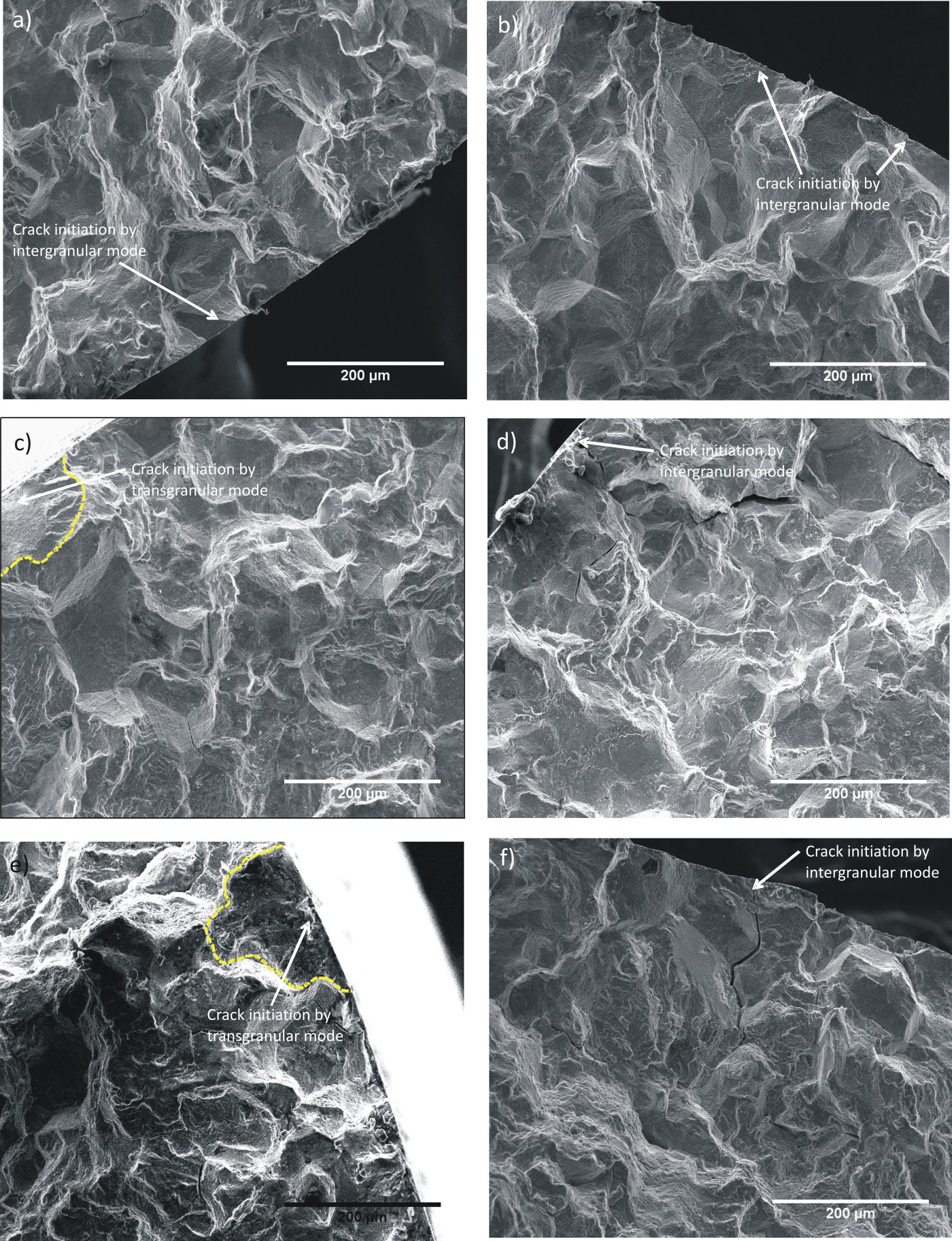
To account for the intergranular crack initiation in fatigue failure specimens with tension hold, the cross section below the fracture surfaces of all fatigue failure specimens were examined under electron probe micro analyser (EPMA) and a few representative damaged microstcructure are shown in Figure 9. The grain boundary provides an easy path for oxygen to diffuse during tensile hold. The grain boundaries intersecting the surface were observed to be cracked and oxidised in fatigue failure specimen with tension hold as shown in Figure 9(a). Apart from grain boundary oxidation, voids were also observed along the grain boundaries at several places in the interior of specimen and can be seen in Figure 9(b). The damage of grain boundaries in fatigue failure specimen with compression hold was comparatively less severe. One such image containing an oxidised grain boundary in fatigue failed specimen with compression hold is shown in Figure 9(c). It seems that the compression hold does not provide an easy path for crack propagation and internal oxidation to take place and so there was very less number of internal cracks and void formation as compared to tension hold as shown in Figure 9(d).
EPMA and optical micrographs showing the microstructure degradation after fatigue test of alloy IN740H at 760°C with 5 min hold time in tension hold (a,b) and compression hold (c,d).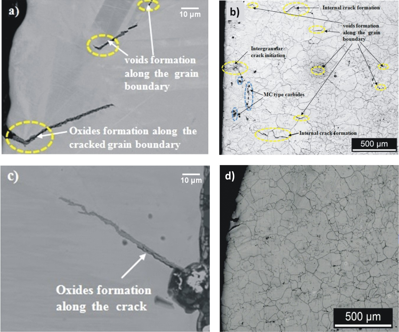
The surface examination of the failed specimens were carried out under SEM to understand the behaviour and role of oxide scale during fatigue tests with different hold conditions. A few representative SEM micrographs of oxide scales of fatigue failure specimens are shown in Figure 10. Prominent cracking of a surface oxide layer was observed on a fatigue failure specimen with tension hold as shown in Figure 10(a). The oxide surface cracking observed on the surface of fatigue failure specimen with compression hold and both hold was not as prominent as it was observed in tension hold as can be seen in Figure 10(b,c). From the bulk EDS analysis of the surface it is observed that coherent chromium oxide layer is formed on the surfaces of all the fatigue failure specimens at 760°C and Δϵt/2 = 0.4%. As the alloy IN740H has more fatigue life in compression and both hold than the tension hold, the chromium content in the oxide is found to be more. The thick adherent chromium oxide layer, delay the crack initiation stage. So this could be one of the probable reasons for having more fatigue life in compression hold and both hold when compared to than the tension hold.
SEM micrographs showing oxide scales on surface of fatigue failure specimens at 760°C and Δϵt/2 = 0.4% with hold of 1 min in (a) tension hold, (b) compression hold; and (c) both hold.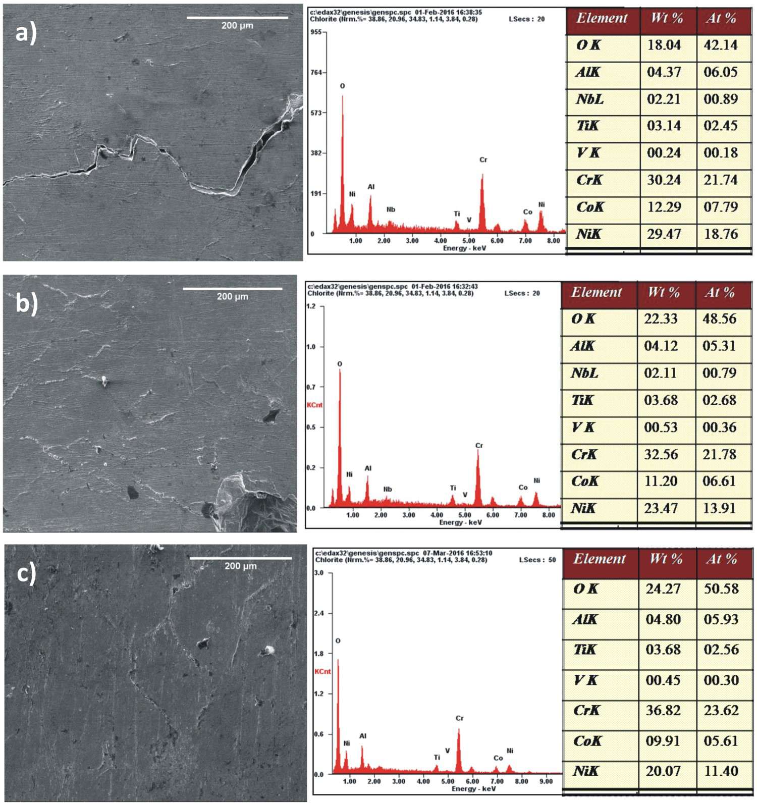
Discussion
The strain controlled fatigue tests were carried out to mimic the creep-fatigue damage that takes place in boiler materials due to thermal fluctuations during the operations. Particular strain amplitude of 0.4% was selected because the strain in actual operations due to thermal fluctuations is well below this value. Stress relaxation takes place in the strain dwell tests. The cyclic response of strain results in hardening/softening of material depending on the nature of materials. Creep-fatigue interaction is a combination of both time dependent and time independent processes. The creep-fatigue could be studied either by carrying out the test by introducing different strain rate or by providing the dwell at peak strain. In the present study, the effect of different dwell modes at operating temperature of the material, i.e. 760°C was studied. The evolution of stress during a strain controlled test is a result of microstructural changes taking place in the material. The correlation between the mechanical responses and the damage mechanism would be an important input from the designer point of view.
From the creep-fatigue testing of alloy IN740H at 760°C, it is observed that deformation curve as shown in Figure 3(a–c) is similar to fatigue tests conducted without hold time [3]. Shifting of the stable hysteresis loop of hold time fatigue tests with respect to the stable hysteresis loop of 0 min hold fatigue test was observed under creep-fatigue loading conditions as shown in Figure 4. The magnitude of shift is observed to be proportional to the magnitude of the relaxed stress during the hold period as shown in Figure 4. From the hold time fatigue tests, it is observed from Figure 5 that compressive mean stress develops during the tension hold whereas tensile mean stress develops during the compression hold. Thus asymmetry behaviour is shown. The nature of mean stress developed during hold time fatigue tests were similar as reported by Lord and Coffin [17] and in [18]. The magnitude of shift in hysteresis loop with respect to stable hysteresis loop of 0 min hold fatigue test increases with increase in the dwell time (ref. Figure 4). It was also observed that the magnitude of mean stress developed during the fatigue tests increased with increase in the dwell time (ref. Figure 5).
The effect of other variables like reduction factor R, plastic strain and hysteresis energy affecting the fatigue life under the creep fatigue loading conditions were also studied. It was found that these variables had a predominant role in the reduction of fatigue life in tension hold. It was analysed that there was a marginal decrease in plastic strain accumulation in the tension hold with increase in hold time when compared to the compression and both hold which could be one of the reason behind the less fatigue life in tension hold. The creep and fatigue fraction derived was found to be well below the linear damage summation rule line and bilinear line of RCC-MRx of alloy 800H as shown in Figure 7.
Tension hold during fatigue tests has been reported to be more damaging to fatigue life than compression hold in several nickel base superalloys such as 617 [19], PM1000 [20], MA 754 [21], steels such as 2.25Cr1Mo steel [22], 304L [23] and 316LN [24]. The reasons attributed to this are grain boundary oxidation [20], creep cavitation [21] etc. However, for martensitic steel 9Cr-1Mo, Fournier et al. [25] found that there was no evidence of creep cavities formation or creep damage under tension hold during creep-fatigue loading condition. The reduction in life in [25] was attributed to the viscoplastic deformation rather than diffusion process. Environment plays a major role in initiation and propagation of cracks. In the present investigation it is observed that with increase in the hold time the crack initiation mode changes from transgranular to intergranular as shown in Figure 8. As reported in [26], with increase in the dwell time during fatigue tests the fracture is similar to that of pure creep conditions. It is also reported that internal crack initiation sites mainly by cavitations along the grain boundaries are prominently formed in fatigue failure specimens with tensile hold, which leads to drastic reduction in fatigue life in nickel base superalloy PM 1000 [20]. The occurrence of environment-assisted crack initiation was also seen under creep-fatigue loading conditions as shown in Figure 9. The occurrence of more numbers of voids under tensile hold creep-fatigue loading conditions, results in internal crack along the grain boundary by combining of voids ahead of the advancing crack tips as demonstrated in Figure 9(a). Crack advance in creep-fatigue tests is thus controlled by cavitation due to stress assisted diffusion of voids [20], and subsequent fracture along the grain boundaries can be seen in Figure 9(b). Thus intergranular fracture is controlled by local diffusive process.
Formation of cavities along the grain boundaries during fatigue testing of austenitic stainless steel under tensile hold has also been reported by Nam [27]. But in [27], cavities were not observed, when fatigue tests were carried out under compressive hold. The grain boundary voids which are produced during the slow straining on the tensile side of the hysteresis loop are not completely healed during the compression [22]. These grain boundary cavities lead to intergranular crack initiation. Cyclic testing with both hold and compressive hold in the present study, there was an absence of intergranular cavitation in the gage section interiors. The absence of interior grain boundary cracking during compression hold and both hold creep-fatigue testing indicate that the intergranular crack propagation is driven by interior grain boundary separation exacerbated by the application of a tensile hold, rather than by environmental factors leading to weakening at grain boundaries [28]. SEM studies by Caroll et al. [28] also shows that material subjected to compressive stresses during the high temperature showed no cavitation or void formation along grain boundaries. This implies that suppression of cavitation take place during the compression hold which helps to increase the fatigue life. The fatigue life in compressive strain hold was similar to that under the symmetrical triangular wave in austenitic stainless steels, but decreased notably in tensile strain hold [29]. While in alloy 617 the fatigue life was decreased with hold in compressive strain more than by the symmetrical triangular wave; the reduction in life was related to the growth of intergranular cracks [25]. The study by Fournier et al. [30] on 9Cr-1Mo steel states that mean stress effect and environmentally assisted crack initiation was responsible for the deleterious effect in compressive hold and having lower fatigue life than the tensile hold. Finally from the above discussion it could be concluded that the creep-fatigue damage depends on microstcrutural parameters such as grain size, strength of grain boundaries, diffusivity along the grain boundaries etc.
Conclusions
The study of LCF behaviour of alloy IN740H at 760°C with dwell time introduced in tension hold, compression hold and both hold for 0, 1, 5, 10 and 30 min duration leads to the following conclusions:
Hold time adversely affects fatigue life of alloy IN740H at 760°C for all types of holds. However, the drop in fatigue life is more significant during tension hold and both hold. The cyclic deformation curves shows stable region followed by continuous softening in tension hold while prominent hardening is observed in compression hold followed by continuous softening till failure. From the creep fatigue interaction diagram it is seen that the cumulative damage resulting from creep and fatigue interaction lies between the bilinear damage rule line of RCC-MRx of alloy 800H and ASME N-47 of alloy 800H & draft code case of alloy 617. The fracture initiation is intergranular when hold time is introduced during peak tension, peak compression and in both hold due to grain boundary oxidation. From the cross sectional studies, it is observed that voids and coalescence of these voids leading to the formation of internal cracks at the grain boundaries is the reason behind for having decreased fatigue life in tension hold than in the compression/both hold.
Footnotes
Acknowledgements
The authors are very thankful to the entire member of Material Evaluation Laboratory, NML – Jamshedpur. The authors would like to acknowledge Dr Tom Gibbons, Consultant in Materials Technology, Wilmington, North Carolina USA for arranging the material for the present study.
Disclosure statement
No potential conflict of interest was reported by the authors.