
Abstract
Three-dimensional printing/digital or additive manufacturing is an area that is taking off with considerable rapidity and magnitude. In the same time, non-destructive evaluation (NDE) is playing an important role in the acceptance of additively manufactured parts, in order to provide the required confidence in the quality of the part and its expected safety and performance while in service. This article represents a summary addressing the subject of applicable NDE techniques to detect manufacturing anomalies and service-induced flaws. The topic is relatively new, attracting much research attention and funding, while in the meantime manufacturing processes are continuously improving. The number of publications covering additive manufacturing is increasing exponentially, and everyday new articles, conferences, and workshops are bringing out new information.
Introduction
Additive manufacturing (AM) is under continuous development and upgrading, it has a wide range of applications from food, jewellery, and fashion to human organs and space. It has captured the interest of industry, the support of governments, and the involvement of various research groups. In spite of continuously emerging applications, there are three major drivers for metal-based AM, these being aerospace, automotive, and biomedical fields. This does not mean that other fields are evading this technology, especially when there is a need for a one-of-a-kind or customised part; however, the overall high startup cost is a limiting factor for large scale implementation.
The primary purpose of non-destructive testing (NDT) is to detect discontinuities in an as-manufactured part; while non-destructive inspection (NDI) has the goal of finding flaws when the part is in service. For these, the accept/reject criteria needs to be established based on the intended use of the part, combined with the criticality of a defect for that specific application. NDT and NDI, along with materials characterisation, create the broader area of cross-disciplinary engineering called non-destructive evaluation (NDE). NDE can overcome some foreseen limitations of AM technology, such as feedstock quality, standardisation of the equipment or process parameters, qualification and certification of the parts, optimisation of the processes, quality of the final product and its in-service integrity [1]. Moreover, there are a number of factors associated with AM that are making the NDE applicability quite challenging, prompting a multipronged consideration, as discussed herein.
With the variability in the manufacturing processes and printing equipment, the need for NDE is more stringent for AM than for conventional manufacturing. Adoption of AM for critical parts is intimately tied to the NDE's role in qualification and verification of the manufactured parts. Once technological advancements in AM processes achieve products that are stable, controlled, and repeatable, then appropriate acceptance criteria through NDE will be necessary to assure the integrity of these AM parts. Destructive testing plays also a role in this development and helps in understanding the capabilities and limitations of the manufacturing process and its effect on the mechanical properties of the AM part, but also to validate the inspection results and their relationships to the part performance.
To embrace AM, in addition to the cost and availability of 3D printed metallic components, one has to take into account the mechanical capability of the part, and the ability to inspect it. The complex geometries, residual stresses, the special gradients of the material properties, as well as the distribution of discontinuities, are all affecting the quality and performance of the additively manufactured part. Application of NDE for AM is viewed as an area in which additional research and collaborations are necessary [2]. NDE is a piece in the trust circle linking manufacturers and end users.
Since this article is an attempt to briefly summarise existing literature findings on NDE of metal-based AM parts, a simple search in the Scopus database was performed to identify publication trends over the last few years [3]. Articles containing the terms ‘metal’ along ‘additive manufacturing’, ‘3D printing’, or ‘digital manufacturing’, as in title, abstract or keywords of a publication, show an almost exponential increase in the number of publications. From 2008 to 2018 there have been about 20,000 publications on the topic, distributed as shown in Figure 1.
The number of publications related to additive manufacturing as mentioned in Scopus database.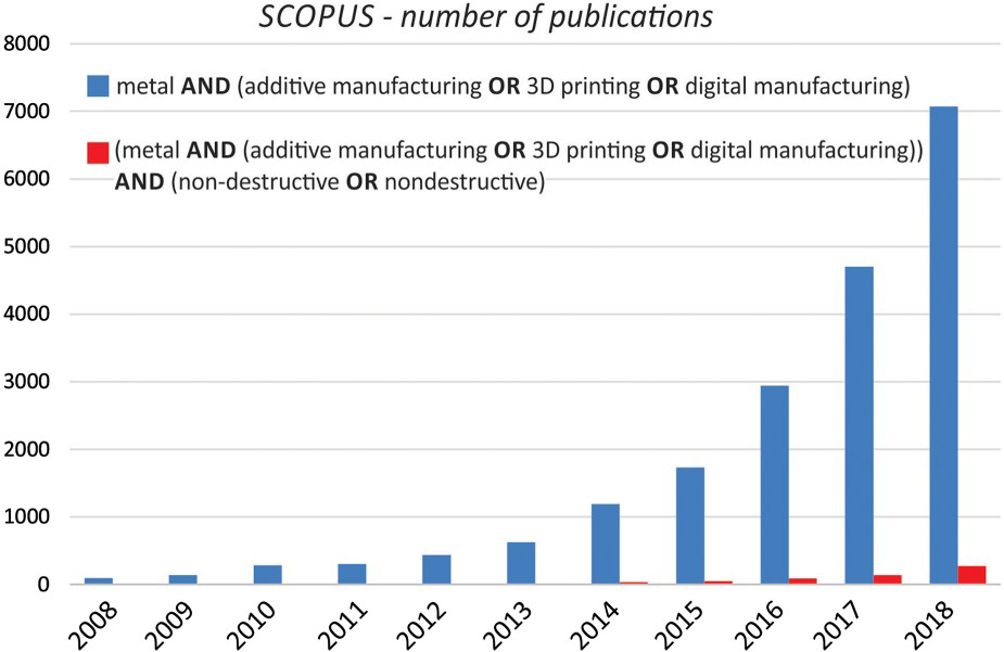
It is extremely interesting to find that searching for the same words, but in combination with ‘non-destructive’ or ‘nondestructive’ returned about 600 results over the same period of time, with almost a half of those published during 2018, reflecting a growing interest on the topic [3]. The AM technology had transitioned in this time span from a rapid prototyping capability to the serial production of some parts and components. The need for NDE, although widely emphasised in the literature, has not been defined despite its role in every stage of AM, from the feedstock to the in-service product. Established procedures will need to be adapted to the realities of AM, and new techniques may be developed along the way. Even standardised destructive test methods are deemed inappropriate for AM, as they assume material homogeneity and test specimen that may not be practical for AM materials [4].
Typical AM flaws
As with all manufactured parts, the additively manufactured ones will contain discontinuities and flaws. They are categorically anisotropic in terms of their elastic and electromagnetic properties, making ultrasonic and electromagnetic investigation techniques, respectively, direction-dependent. Porosity and lack of fusion are the most commonly known flaws in AM and they occur primarily between the layers, reducing the load-bearing area of the part and its mechanical properties. There is a relationship between the raw material, process parameters, post-processing steps, on one side, and the type of discontinuity that can exist for the as-manufactured part or occur during the in-service life of a part, on the other. At this time, definite metrics to characterise the AM part quality are missing. Owing to the novelty of AM, the structural performance of each part, despite efforts for stable and controlled manufacturing processes, needs to be confirmed via non-destructive characterisation techniques.
It is challenging to detect anomalies during manufacturing, but appropriate adjustments in process parameters (such as laser power, process speed) would allow for repeatable characteristics of the final product [5]. Once a set of parameters is determined to produce a high-quality part, the process of manufacture is established.
Repeatable intentional discontinuities could be reliably seeded into AM parts, to be used for referencing and calibrating non-destructive instrumentation. Such testpieces shall be developed starting from the existing knowledge of inspecting conventionally manufactured parts. From an NDE perspective, AM poses some unique challenges: complex part geometry, embedded flaws, rough surface finish, lack of physical references with the same material and processing history as the evaluated part, lack of knowledge for seeding flaws, high part anisotropy, unknown critical defect sizes, lack of procedures, no mature in-situ monitoring techniques [6], and many others.
Lack of fusion, porosity, trapped powder, layer shift, unconsolidated powder, inclusions, delaminations, and voids are examples of discontinuities that could be found in an AM part. Lack of understanding of the effect-of-defect is contributing to the need of developing NDE qualification and certification means. For example, powder density, particle size distribution, melting temperatures, and powder flowability all affect the surface roughness and mechanical properties of the part. The powder itself needs to be inspected, to have no contamination or moisture, and particles to be of the right size and shape, especially for re-used powder beds. Pores and voids pose risk for failure through tensile overload and fatigue crack growth. Fatigue life is known to decrease in the presence of larger pores, near-surface pores, clustered pores, and irregular ones [7]. However, it is not the largest spherical pore or void that causes the greatest risk, but the one with the highest aspect ratio [8] and perpendicular to the load direction that creates the highest stress concentration.
NDE techniques and materials characterisation are playing important roles in AM, from the feedstock material, process optimisation, quality assurance, to the in-service inspection. Highly anisotropic, very fine microstructure, presence of micro-porosity, cracking, lack of fusion, and inclusions in the deposited material are characteristics of additively manufactured parts that are completely different from those of conventionally manufactured ones. For instance, different microstructure could have significant effects on static and dynamic strengths. Microstructural analysis could link the non-destructive findings, in the form of distinctive discontinuity signatures in the acquired signals, to mechanical properties and mechanical tests, and ultimately to the performance of the part, as schematically represented in Figure 2. Moreover, this information can be fed back into the manufacturing process, to adjust the parameters that will result in a part or component of improved quality. Variation in materials properties is, in most cases, associated with manufacturing process variability that leads to microstructural changes and part anomalies [9]. Microstructure is heavily affected by the manufacturing process and the thermal history of a metal part.
The linkage between microstructure, mechanical properties, and part performance realised via NDE in additive manufacturing.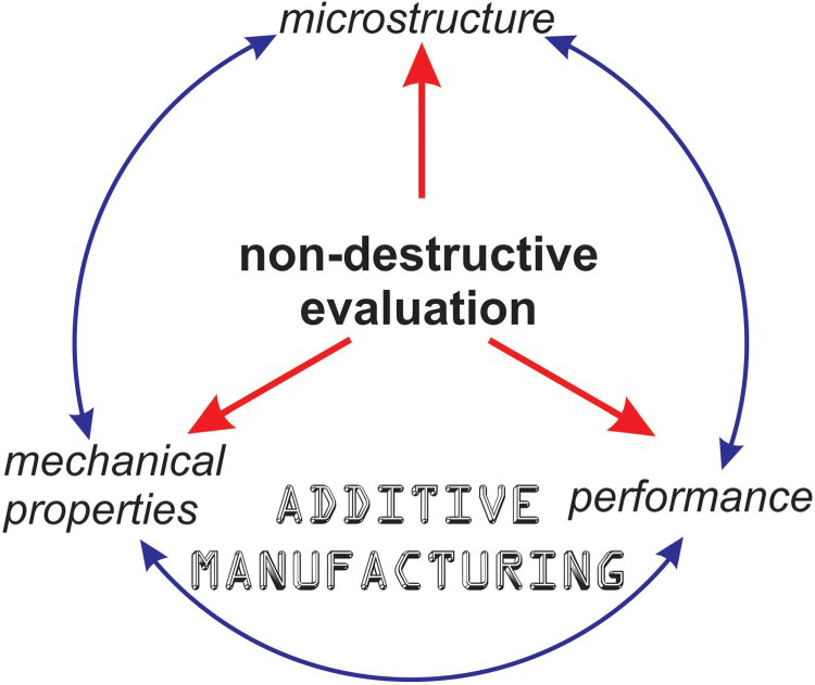
Since the typical AM build process, with layers built, say in the z-direction prohibits volumetric defects of significant height; the NDE focus should be on finding planar defects, laminar cracks, etc. in the plane of a single layer or between layers [4,6]. Some other AM characteristic defects are due to spatter, agglomerated powder particles, part deformation. Some of them would be detectable via specific NDE techniques, but there is no clear understanding what is the type and size of allowable discontinuity, i.e. one that would not produce failure of the part under normal operating conditions [10]. However, the detection threshold of the chosen inspection technique needs to be able of finding discontinuities smaller than the maximum allowable discontinuity size. The list below includes the most commonly encountered flaws in metal-based additive manufactured part:
Porosity is due to contamination in the feed material, inadequate choice of manufacturing parameters, entrapped gas, and creation of vapours of feedstock material constituents. Hot isostatic pressing (HIP) is the after-build process that can partially eliminate porosity, but cannot deal with large pores. Porosity is the most common type of flaw in AM parts, and it has negative consequences on the strength and fatigue performance of the material. In direct energy deposition (DED) processes, a high powder flow rate can result in increased gas entrapment [10]. For powder bed fusion (PBF) processes, such as selective laser melting, the interaction of the laser beam with the powder has the potential to entrap gas porosity and create a lack of fusion. These features could be abundant and much smaller than the ones encountered in the cast or wrought counterpart; the grain size and orientation are also different [8]. Voids are created when the energy level of the beam changes, leaving holes that are covered by subsequent passes or deposited layers. An interruption of powder supply can also introduce in-layer voids. Cracking can be produced by different solidification stresses within multi-material parts and large build-ups. Additionally, thermal properties mismatch between the built material and the build plate can induce cracking. Crack orientation is important since high aspect ratios result in high stress concentrations [9]. Thermal gradients can generate cracks in the part, especially when there are large differences in the thermal properties of the baseplate and that of the manufactured part [10]. Rapid cooling rates can also lead to distortion and cracking. Inclusions are due to debris existing in the feedstock or presenting in the building environment. Partially melted particles, i.e. spatter, can splash away and land on the powder bed or on other areas of the built part. Spatter particles can occur in the laser path in other building regions reducing dimensional tolerances and acting as defect nucleation sites [11]. These particles are usually larger than the layer thickness and prevent proper adhesion of subsequent surfaces. Keyhole flaws are non-spherical porosities due to the entrapment of gas in the material during the PBF manufacturing. Delaminations can be created between the layers of the deposited material due to different melting temperatures. Warpage is introduced in AM parts by the existence of residual stresses, and, in some instances, when the built part is separated from the baseplate. Residual stresses are regularly introduced during the manufacturing of parts due to different thermal gradients, resulting in creation of high intensity stress regions, micro-cracks, and recrystallisation [10]. Residual stresses and deformations can occur when the AM part is removed from its supporting plate, when this is used [12]. Most of the times, these are taken into account during the design stage and removed by post-processing. Lack of fusion flaws occur when a newly deposited powder layer is not adequately heated and melted, a fact that prevents fusion on the previously deposited layer [1]. Lack of fusion might be also due to high deposition speeds [10]. Unconsolidated powder/lack of fusion is the result of a poorly developed manufacturing process or poor parameter selection; it is fixable in-process, if detected in time. Surface roughness could be also considered a type of discontinuity; in most cases, the top surface roughness differs from that of the side surfaces. Roughness is related not only to the powder/wire size, but also to the beam energy, beam size, and building speed [13].
Roles of non-destructive evaluation
In many industries, the acceptance of AM depends on NDE to detect possible flaws and understand the effect of these flaws on part performance [4]. In the aerospace industry, AM is seen to benefit the manufacturing of new structures, repair of old ones and the market of spares and replacement parts [9].
Although many discontinuities in AM parts are related to porosity and lack of fusion, others are the result of the properties of the feed material and the direction of the heat flow during the manufacturing process. For example, changes in the scan path result in different macrostructure [13]. NDE for AM has paramount implications at all the stages of the AM part lifespan, as exemplified below:
for feedstock characterisation and quality assurance, as in-process monitoring, for closed-loop feedback in the manufacturing process, for in-situ detection of material discontinuities, for process-induced defect detection, for the non-invasive characterisation and qualification of the as-built AM part, for the dimensional analysis of the post-processed AM part, and for detecting flaws in the in-service AM components.
Figure 3 shows a block diagram of various stages of AM and the corresponding roles of NDE/testing/inspection.
Schematic showing how various aspects of NDE are necessary for all the stages of additive manufacturing.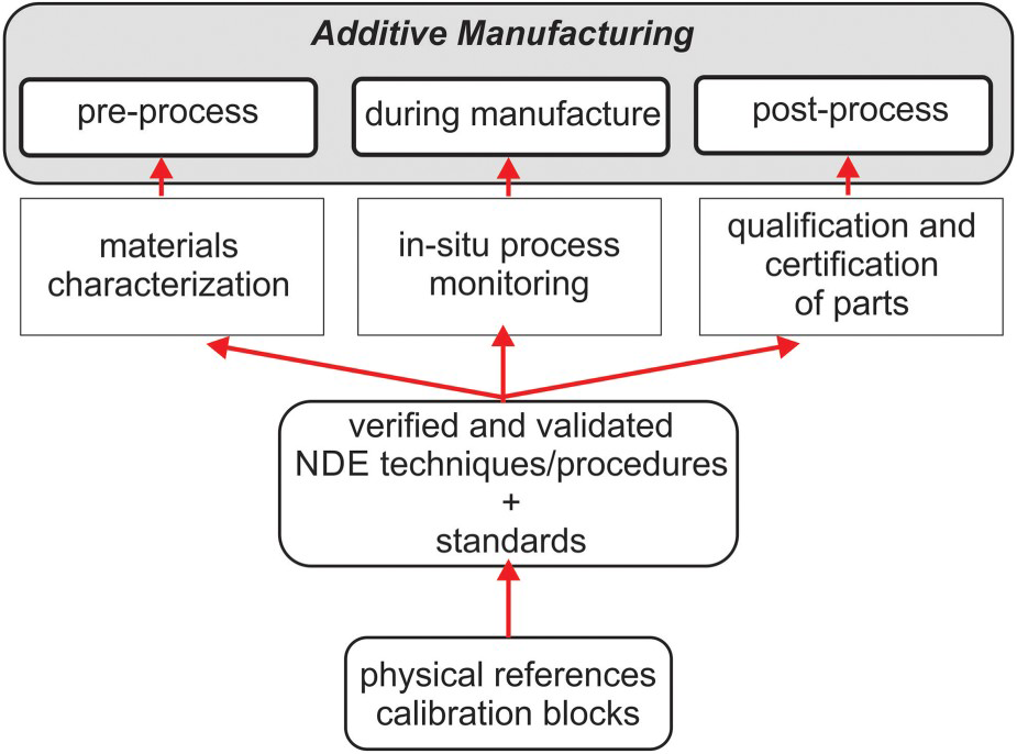
Flaws introduced during manufacture can be mitigated by process monitoring and control, but only few current AM machines are equipped with feedback loops for quality control purposes. However, some techniques have been found to offer limited success: thermal imaging had been proposed to monitor the weld pool temperature; optical imaging to measure shape and distortion during the build, and others for detecting manufacturing discontinuities, or residual stresses [14]. Moreover, NDE has a role in understanding the effect of post-processing protocols, such as HIP, heat treatment, surface machining, and shot peening.
It has been proposed that NDE techniques be optimised for AM processes and address both in-situ and post-process applications, with long-term plans of having NDE techniques integrated into the AM machines [5].
NASA has taken a comprehensive approach to addressing NDE applications for metal-based additively manufactured parts, having different Centers working on different alloys or manufacturing processes, while employing NDE techniques for the characterisation of the parts. All conventional NDE methods were used in this evaluation and their usefulness was addressed, with computed tomography (CT) being the technique most commonly employed for post-process evaluation. For this reason, computed radiography gauge blocks were used to assess the dimensional accuracy of the method [2,14]. Thermal imaging was mainly used for process monitoring, as inspection during manufacturing. Material properties are required to meet the design requirements; the manufacturing process is optimised based on these design needs [8].
There are important technology gaps in all the steps of AM, from material property control to clear understanding of the fracture mechanics and reliable quality assurance measures [6]. The characterisation of the feedstock, such as powder composition, particle size, and other consistency characteristics are relatively matured. However, the chemistry, size, flowability, and morphology of the raw materials need to be known, as well as their reuse (for powder) and recyclability properties [15]. The monitoring techniques for in-process characterisation and feedback control need to take into account homogeneity, residual stresses, and distortion. Post-process qualification, such as shot peening, HIP, also have an effect on the properties of the part, and on the response of the NDE techniques [2]. Development of physical references for NDE has to consider the critical damage size for the additively manufactured part, and be built accordingly. NDE references are seen to have a process validation role, to assure production of high-quality parts, but also to verify that the in-service inspections of AM parts are correctly interpreted. Since AM processes are expected to be used in the manufacturing of complex geometries, the ‘effect-of-defect’ on the part is not yet understood, therefore critical defect sizes are not properly quantified and reference blocks are scarce [2].
Although most of the NDE validation shall be performed through destructive tests, physical reference standards are also needed to verify and validate NDE data, understand the discontinuity signal and define acceptable limits, as well as determine the reliability of specific techniques [2,14]. Physical reference samples demonstrate the capability of an NDE technique for a specific type of discontinuity [6]. NDT reference blocks developed for welding and casting are not recommended for AM applications [4]. One reason for this being that the critical defect size in a cast or AM part, even of the same alloy, may be different.
In-situ and real-time characterisation of AM parts have a double benefit: part qualification and process control [16]. Identifying issues during manufacture, as early as possible, could minimise losses and prevent waste of the feedstock material [1,17]. Each element of the AM technology, materials, equipment, and process must be qualified to assure reproducibility of high-quality parts.
Testing and inspection approaches
This section summarises the most encountered NDE techniques discussed in the literature, as applied for the characterisation of the raw material, in-process monitoring, quality assurance, and in-service inspection of metallic AM parts.
Optical methods
The surface roughness of AM parts is normally measured by profilometry, either optical (laser, LED) or contact-based. Three-dimensional scanning or contouring techniques are also used to inspect for geometric accuracy and dimensional analysis [13]. Laser scanning and structured light are optics-based techniques that are used to evaluate the surface of the AM part, as well as for dimensional analysis and detection of residual stresses, as introduced by warping. Optical tomography is applied in-line, to monitor hot spots [18].
Penetrant testing
The liquid dye penetrant inspection method is meant to detect surface discontinuities based on capillarity effect: a dye liquid is absorbed within the discontinuity, such as a crack or surface-open porosity, while a subsequently applied developer is driving the colourful dye out of the defect, concomitantly providing a contrast background colour. The method is simple, intuitive, inexpensive, and used to detect manufacture-related or service-induced flaws. The evaluation is normally performed under ultraviolet light when using fluorescent dyes. The examined metallic specimen needs to have a relatively smooth surface, though not normally the case for additively manufactured parts, which have rough surfaces and need some form of preparation, i.e. machining, before liquid penetrant inspection. However, surface machining can mask out potential flaws, by closing the path for capillary action of the dye penetrant.
Ultrasonic waves
Linear ultrasonics are used to characterise the AM part in terms of its elastic properties. Non-linear ultrasonic waves are used to determine strength-related properties, as it happens with the characterisation of solids, but applications to parts made by additive processes come with its expected challenges, i.e. coupling, complex geometry, wave attenuation, etc.
Ultrasonic techniques could be used in AM for dimensional analysis, such as part thickness measurement, as well as for detection of internal discontinuities. Typical wave frequencies are between 0.5 and 25 MHz, while both immersion and contact techniques are applicable. Ultrasonic inspections are customarily employed on flat objects or on parts with parallel surfaces; this may not be the case for some additively manufactured components. Moreover, the as-built part surface might not be smooth, and better surface finish may be required to assure ultrasonic inspectability.
The ultrasonic technique uses grain scattering, diffusion, and attenuation to identify imperfections in a solid part. Ultrasonic wave attenuation versus the grain size is one approach to microscopically characterise metal additive manufactured parts.
The elastic properties of a selective laser melting (SLM) Al–10Si–1Mg wt-% part were measured using ultrasonic waves for characterisation against a baseline represented by the properties of Al 6061-T6, due to similar thermal histories, but also with casting alloy A360, due to identical chemical composition [8]. The longitudinal and shear ultrasonic wave velocities were used to calculate the Poisson's ratio and the elastic modulus of the testpieces. These mechanical properties are determined on cubes of AM coupons, in order to take into account the part anisotropy, and to find the relations with the acoustic propagation characteristics of the material [19]. The approach is believed to be more accurate than using the stress–strain curve of a tensile test [8]. The results for SLM and wrought materials were very similar, and the differences encountered in the ultrasonically determined elastic properties were considered being due to different composition and microstructure [8].
In-process quantification of the porosity variation has been attempted for simple geometry structures using the wave speed variation with the material density [10]. Other studies used an ultrasonic transducer fixed on the bottom part of the build platform. For example, Rieder et al. used a 6.35 mm diameter, 10 MHz longitudinal wave transducer to monitor an Inconel 718 part while being manufactured, with 250 layers of 40 µm layer thickness [18]. The effect of the laser power on the sound velocity as the part was being built has been investigated. Similar approaches had been reported, with shear wave ultrasonic probes not in direct contact with the build plate, but in pitch-catch configuration and immersed in ethylene glycol, monitoring an evolving laser melt pool [16].
The laser-generated ultrasonic waves technique, which uses thermal stresses to generate vibrations inside the testpiece is seen as a technology of potential for the inspection of additively manufactured parts of high surface roughness and complex surface geometry. The technique has non-contact requirements, ability to inspect parts of complex geometry, and suitability for in-situ and on-line inspection during the manufacture. Moreover, it could be used in a high temperature environment and provides high resolution inspections [20]. Good agreement between laser ultrasonics with synthetic aperture focusing technique processing and micro-CT imaging on Inconel 718 and Ti–6Al–4V coupons had been reported [21]. Flaws such as lack of bonding or lack of fusion, as well as porosity were detected by both methods. The drawback of the technique is represented by sensitive instrumentation.
Acoustic emission
The acoustic emission technique is considered a branch of the ultrasonic method of NDE, with the ultrasonic wave generated by passive means, through the emission of energy from localised sources, such as due to a propagating crack, plastic deformation or other stress relaxation mechanisms [22]. An important feature of the acoustic emission is its irreversibility; the previously applied stresses need to be exceeded in order for the acoustic energy to be released [20]. The location of the acoustic signal could be found by triangulation. The technique does not relate to the crack size, but to its rate of growth.
Aluminium alloy (AlSi9Cu3) parts manufactured by casting versus similar ones manufactured via SLM were compared in terms of fatigue properties using acoustic emission [23]. Acoustic emission detects stages of crack initiation and growth, and it has found that SLM material had better fatigue life than the casting counterpart. The print process would affect the microstructure, defects, and surface roughness, and subsequently the sound signature [22].
Radiographic techniques
Radiographic techniques are ideal for detecting internal defects within the volume of the examined part. The intuitive visualisation of the inspection outcome is also an attractive feature of radiography. Low density anomalies, such as porosities, lack of fusion, voids have lower-than-background contrast, while inclusions are normally seen as higher density on the radiographic medium, i.e. film, phosphorus plate, or digital radiographic panel. Voltage, current, and exposure time for the X-ray source are adjusted to penetrate a certain material, according to its density. As part of the radiographic techniques, CT is seen as a comprehensive method that uses radiographic two-dimensional results to create a three-dimensional outcome, and able to: (a) detect embedded defects, (b) interrogate inaccessible features, (c) confirm effectiveness of post-process treatments, and (d) characterise and qualify AM parts. The drawback of this approach occurs for detection of cracks, since less than optimum orientation of the ray beam with respect to the crack faces might not provide sufficient attenuation [14]. Although CT techniques are suitable for detection of internal defects, there are limitations of the size of the testpiece that could be investigated, since CT systems have a limited scannable field. With the increase in AM part dimensions, CT inspections would become more difficult.
A multitude of reference blocks has been manufactured to determine the detectability limit of radiographic systems for evaluating small, artificially introduced geometric features, especially porosities and cracks. However, two-dimensional features can be missed due to the orientation of the X-ray beam. Micro-focus CT can be used for dimensional analysis as well, especially due to the high resolution of the technique. The typical CT industrial system has an energy ranging from 160 to 450 keV, even higher for some; this energy level indicates both the resolution and depth of penetration. The resolution of micro-CT systems can reach down to 10 µm in 100 mm thick steel, with higher resolution in thinner or less dense materials. It is recommended that the CT scanning orientation should be perpendicular to the build direction, since manufacturing discontinuities occur, in most cases, in the build plane. CT is considered the best tool to detect the size, shape, and distribution of pores in AM parts. The pores size and distribution vary from part to part, depending on the material and the manufacturing technology employed. It could be used to observe the effect of the HIP process, and its role in closing pores and increase the density of a part.
Electromagnetic techniques
From an eddy current NDE technique standpoint, the typical AM testpiece has through thickness and in-plane (surface) anisotropy due to the directional material deposition process. The eddy current testing (ECT) of additively manufactured parts need reference and calibration blocks, which need to be, in turn, fully characterised to assure their purpose [24]. Mechanical testing and metallographic analysis of coupons manufactured from the same AM block as the reference coupon should be used for NDE technique validation.
Previous studies have shown that ECT of additively manufactured components is very similar to the ones used for conventionally formed parts, but with higher noise level due to surface roughness; however, the effect of the fabrication process on the grain structure, and consequently on the ECT signals, needs to be understood [2]. ECT techniques are especially applicable for detection of surface and near-surface features; they are not able to sense deep volumetric discontinuities. The electromagnetic techniques are influenced by the probe-to-part separation (i.e. lift-off), material electric conductivity and magnetic permeability, as well as the part thickness. Factors affecting these parameters also influence the technique response to features such as: porosity, voids, cracks, lack of fusion, as well as inclusions and residual stresses.
When eddy current arrays are used, the resolution of ECT depends on the sensors size and array spacing, as well as on the spatial resolution of the scan. Acquisition rate and scanning speed also play a role, but their respective effects are normally neglected or adjusted for. Typical resolutions are of an order of 1 mm [24]. In the case of additively manufactured parts, surface roughness or waviness can negatively influence the discontinuity detection capabilities of ECT, although probes do not necessitate contact with the part under test. Surface eddy current inspection often requires covering of the part surface with a thin non-conductive tape, since the surface roughness could damage the probe.
Before an actual inspection is performed, the eddy current instruments undergo performance verification measurements, according to manufacturer specifications. This is normally done on a calibration testpiece, to help adjust the instrument settings, such as sensitivity, gain, phase, frequency of the instrument [25]. Reference blocks, usually containing deliberately introduced discontinuities, are used to gauge the defect detectability of the technique.
One study looked at creating specific branched defects, such as in the case of stress-corrosion cracking, via additive laser powder bed manufacturing, as reference anomalies to validate ECT procedures [25]. The crack width turned to be about 30 µm, smaller than the eddy current probe resolution.
The magnetic Barkhausen noise technique has been proven to have potential for stress evaluation of ferromagnetic steels [26], but not investigated for additively manufactured specimens. Magnetic particle inspection could only detect surface discontinuities, and only in ferromagnetic materials. Eddy current thermography (also called induction thermography) is applicable to metallic parts, especially to ferromagnetic materials, as discussed in more detail under the next sub-section.
Thermographic techniques
Mapping temperature gradients can reveal the presence of geometric and material non-uniformities that can affect the heat conduction in the metallic additively manufactured parts. The infrared thermography techniques are not only sensitive to the surface properties of the part, but also to the heat transfer inside the examined object. The heat transfer to the part could be conductive, convective, radiative, or inductive. The method is fast, non-contact and can be used to inspect large areas; however, in the case of the metal-based AM, it does not provide the same level of details as ultrasonic or radiography-based techniques.
It should be noted that thermographic imaging is used extensively for process monitoring of thermal gradients. Thermography could be applied while the part is built, as an in-process technique, but for most metallic components, induction thermography is more applicable to reveal surface and near-surface anomalies. Induction thermography uses a time-varying magnetic field to induce a current flow in the metallic part. Owing to local differences in the electrical conductivity of the part, this produces heat, called Joule or resistive heating, whose surface thermal effects are subsequently imaged by an infrared camera.
Discontinuities are affected by the heat flow in the metallic specimen, as they heat up or cool down at different rates than the rest of the part [22]. Hot or cold spots could be due to discontinuities in the part, including geometrical features. The time-based surface temperature and its spatial distribution are dependent on the thermal diffusion of the material, the geometry of the part, and the location and size of the discontinuity. Detectability of a flaw depends on its size and the degree to which its thermal properties are contrasting the ones of the background material. The capability of a technique is affected by the instrument, such as the acquisition period, camera frame rate, sensitivity, wavelength, as well as post-processing algorithms and imaging analysis schemes employed.
Although the discontinuity detection depends on its orientation with respect to the heat flow, it has been reported that thermography could detect subsurface porosity, voids, cracks, and inclusions, in the as-manufactured parts. For this purpose, some metallic additively manufactured parts need to be coated to provide higher emissivity surfaces.
Conventional NDT methods and their capabilities in terms of detecting defects in metal-based AM parts, as for in the volume (V), surface (S), or near-surface (NS).
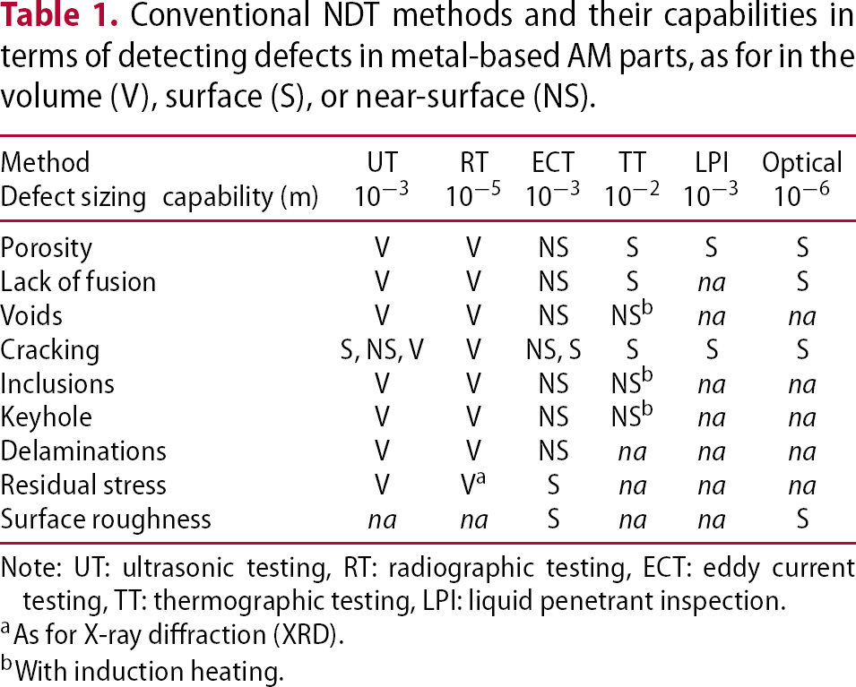
Note: UT: ultrasonic testing, RT: radiographic testing, ECT: eddy current testing, TT: thermographic testing, LPI: liquid penetrant inspection.
aAs for X-ray diffraction (XRD).
bWith induction heating.
Anisotropy, complexity of the discontinuities, variability of the microstructure, etc. are making conventional NDE for metal-based AM very challenging, while quantitative capabilities of various methods and techniques not yet established for AM. Not knowing the critical size and the effect of each individual defect type on the part integrity makes the application of quantitative NDE very intricate. The case of multiple defect types being present in the same part and their cumulative effect complicates evaluation even further.
Conclusion
While the NDE methods and techniques communicated in this article are well established, it is hoped that they will be adapted for metal-based additive manufacture proposes. On the other hand, there are emerging inspection technologies at low technical readiness level that are currently investigated in various research environments, but not fully proven or accepted yet, and hence not discussed in detail herein.
AM brings clear advantages, such as: efficient use of raw materials, reduction of lead-time for production of structural components, fabrication of non-available replacements, and even repair of damaged structures. The technologies and the materials associated with 3D printing are undergoing continuous development and improvement. Regardless the claimed repeatability, stability, and controllability of the AM processes, non-destructive and destructive testing are necessary to gain confidence in these new fabrication technologies. Validation of NDE techniques with the help of destructive testing is necessary. For aerospace applications, fatigue resistance and slow, stable crack growth in additively manufactured structures or structural repairs are of critical importance. The material microstructure dominates the fatigue and fracture performance.
For AM, quality is investigated pre, during, and post built, while during its service, the AM part needs to be periodically characterised to be free of flaws which would endanger the safe operational life. In summary, two critical needs for NDE of AM are: (a) reference blocks, with discontinuities selected in relation to critical defect types, sizes, and locations, and (b) detectability limits of specific NDE procedure/part/defect combination, as required to establish the capability of a technique or inspection procedure. The qualification of a single material-process combination is a costly and extensive undertaking. Reference blocks and standard procedures assure that the same NDE technique, applied by different operators, at different locations, on the same alloy material, and obtained by similar AM processes would yield comparable results. It is clear that current inspection techniques and procedures need to be adjusted for AM, but new, specialised ones might be developed.
Standardisation of AM processes is only recently showing interactions among various groups, organisations, and technical committees, resulting in meetings, forums, and workshops that are well attended. As a result, the NDE for metal-based AM is also starting to receive the necessary consideration.
Footnotes
Disclosure statement
No potential conflict of interest was reported by the author.