






Abstract
Three kinds of pearlitic steels containing different interlamellar spacing and mechanical properties were obtained by different heat treatments. The wear behaviours of the steels and evolution of microstructures under different wear conditions were analysed by block-on-ring wear tests. The results showed that shortening air-cooling time and accelerating cooling rate after rolling dramatically refined the pearlite interlamellar spacing and then enhanced the hardness and strength of the pearlitic steels. The pearlitic steel with a high strength of 1537 MPa was obtained and exhibited the best wear resistance than others. The deformed and fractured cementite in the subsurface layer partially spheroidised induced by deformation and frictional heating. A special layer containing spherical carbide formed and reduced the wear rate of the steel.
Keywords
Introduction
The pearlitic steels containing thin interlamellar spacing possess high hardness, strength, and wear resistance. Because of the special mechanical properties, high-strength pearlitic steels are the vital materials used in manufacturing rails [1–4]. Researchers [5–8] have demonstrated that the hardness and strength of pearlitic steels have a Hall-Patch relationship with the pearlite interlamellar spacing. But the relationships between the wear resistance of pearlitic steels and its microstructure and mechanical properties are not clear.
Baeke et al. [9] simulated the effects of rolling speed, slippage, load, and environmental factors on the friction coefficient between rails and wheels under different rolling wear conditions. Zhou et al. [10] also studied the wear behaviour of pearlitic steel under different slippages. The results indicated that the friction coefficient and wear volume both increase with the increase in slippage. Moreover, the wear depth increased with the increase in wear time. Under the dry and wet conditions, the friction coefficients of the pearlitic steel were considerably reduced with the increase in rolling speed or with the addition of water [11]. During the wear process, the surface microstructure of the steel undergone plastic deformation and the microstructure were refined, and then the hardness of the surface layer increased, and the wear rate reduced [12–15]. In pearlitic steels, the changes in structure decreased potential difference between ferrite and cementite and increased the contact areas between carbon-enriched phase and the friction pair, which enhancing the wear resistance [16–18]. Moreover, many studies showed that pearlitic steels exhibit outstanding wear resistance because it has stronger work hardening ability than other steels under rolling or sliding wear process [19,20]. In addition, the top-most layer containing dissolved cementite was re-austenitised under the influence of temperature and stress during the friction and wear process. The re-austenitised microstructure transformed into martensite during the rapid cooling process [18,21–24]. The wear resistance of pearlitic rail steel is one of the important factors determining the service life of the rail, so its wear behaviour has been the focus of researchers.
In the present experiments, a new type of high-strength steel 80CrSiV was selected for the study of microstructure evolution during the wear process. First, three kinds of pearlitic steels containing different interlamellar spacing were obtained by controlled rolling and controlled cooling processes. And then the wear behaviour of the pearlitic steels with different strength was studied by using the block-on-ring wear test under different rotational speed and wear time.
Experimental procedure
A high carbon eutectoid pearlitic steel with chemical composition (wt-%) of 0.79C–0.81Si–0.28Mn–0.83Cr–0.074 V was smelted and casted into a rectangular ingot with a cross-section of 150 mm × 200 mm, followed by air cooling to room temperature. The ingot was reheated and hot forged into plates with a cross-section of 70 mm × 100 mm, then air cooled to room temperature. All plates were reheated to 1200°C and retained for 3 h followed by controlled rolling and controlled cooling processes. The rolled plates with a final cross-section of 50 mm × 80 mm were obtained. The initial rolling temperature and final rolling temperature are 1050–1060 and 930–960°C. The following processes are included: (a) direct accelerated cooling after rolling for one time, named OAC (b) air cooling after rolling and then accelerated cooling for two times, named TAC and (c) direct air cooling after rolling, named NAC. The controlled rolling and controlled cooling processes are shown in Figure 1 and the specific parameters of temperatures and cooling rates are listed in Table 1. It should be noted that the cooling rate between 940 and 900°C was 39.6°C min–1, while the cooling rate between 600 and 500°C was 18.0°C min–1 during the direct air cooling process.
Schematic of controlled rolling and controlled cooling. OAC, one-time accelerated cooling; TAC, two-times accelerated cooling; NAC, non-accelerated cooling. Parameters of controlled rolling and controlled cooling processes. P, controlled rolling and controlled cooling processes; IRT, initial rolling temperature; FRT, final rolling temperature; ACT, air-cooling time; TAC, temperature after air cooling; CCR: controlled cooling rate; TCC: temperature after controlled cooling; CCT, controlled cooling time; FCT, final cooling temperature.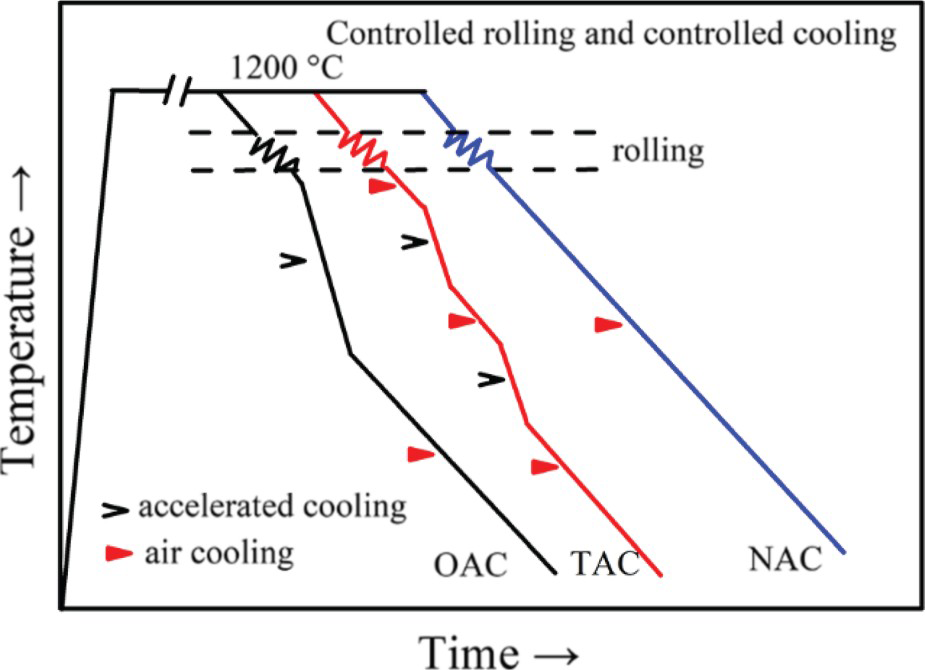

The hardness of the plates from their surfaces to centres (2.5–25 mm) was tested at intervals of 2.5 mm with an HR-150A Rockwell Hardness Tester. The hardness of each point was measured five times, and the average values were calculated. The microstructural features of the steel plates were characterised by scanning electron microscopy (SEM, SU5000), and the samples were polished and etched with a solution of 4% nital. The true pearlite interlamellar spacing (λ0) was calculated with Equations (1) and (2) [25,26].


The cylindrical tensile specimens with the highest hardness in each steel plate were processed with a gauge length of 25 mm and a diameter of 5 mm. Tension tests were performed at room temperature with a tensile rate of 3 mm min–1 by MTS testing machine.
Wear test parameters.
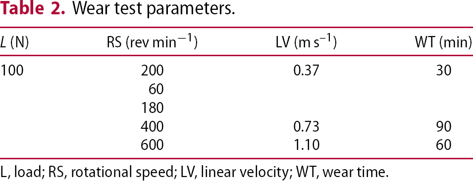
L, load; RS, rotational speed; LV, linear velocity; WT, wear time.
Results and discussion
Microstructure and mechanical properties
During the transformation of pearlite, the minimum pearlite interlamellar spacing is proportional to the eutectoid transition temperature of pearlitic steels and inversely proportional to the degree of undercooling, as shown in Equation (3) [27]. A high degree of undercooling enhances the driving force of the phase transformation from austenite to pearlite and then increases the nucleation rate of pearlite, by which thin pearlite interlamellar spacing can be obtained. Increasing the cooling rate of the steel not only effectively enhances the driving force, but also inhibits the diffusion capacity of atoms and reduces the longitudinal growth rate of pearlite, which refining the pearlite interlamellar spacing [28,29]. The full pearlitic microstructure were obtained in all kinds of steels (Figure 2), but the pearlite interlamellar spacing in the steel obtained by direct air cooling after rolling were significantly larger than that of steels obtained by other controlled cooling processes. The results of the pearlite interlamellar spacing obtained by direct air cooling treatment at different locations were in the range of 273–340 nm. In the steel obtained by direct accelerated cooling after rolling, the range of pearlite interlamellar spacing is 95–120 nm, as shown in Figure 2(d).
(a), (b), and (c) the SEM images of the OAC, TAC, and NAC steels, respectively; (d) the variation of pearlite interlamellar spacing with the distance from the surface.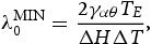
 is the minimum pearlite interlamellar spacing that can be obtained, γαθ is the interface energy of ferrite and cementite, TE is the equilibrium temperature, ΔH is the change in enthalpy, and ΔT is the degree of undercooling.
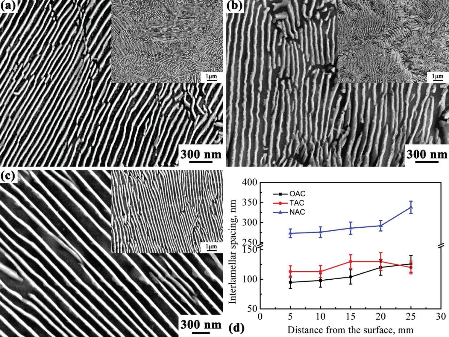
The steel subjected to direct accelerated cooling after rolling only retained for 0.17 min at a high temperature and then was cooled to 454°C at a high cooling rate of 95°C min–1. Compared with the steel air cooled for 2.5 min after rolling, the steel subjected to direct accelerated cooling process failed to remain at high-temperature zones with a low cooling rate. This condition promoted the formation of thin pearlite interlamellar spacing within 10 mm from the surface. With the increase in distance from the surface, the cooling rate of all steels gradually slowed down. The degree of undercooling and driving force was reduced, causing the gradual coarsening of pearlite interlamellar spacing, as shown in Figure 2(d).
The hardness distributions of the steel plates are shown in Figure 3(a). The hardness of the steel after the direct air-cooling treatment was the lowest, the hardness values at different positions were similar and in the range of 32.6–34.8 HRC. For the steel treated by air cooling followed by accelerating cooling, the maximum hardness reached 44.7 HRC at the position of 2.5 mm from the surface. The hardness of the steel tended to fluctuate and exhibited a platform from 17.5 to 25 mm. The hardness of the steel by direct accelerated cooling after rolling reached 44.2 HRC at 2.5 mm and was comparable to that of steel obtained by the b process at this position. Moreover, the maximum hardness reached 46.0 HRC at 5 mm and decreased with the increase in distance from the surface.
(a) The hardness distribution curves from the surface to centre, (b) the engineering stress-strain curves of the three kinds of steels at the position of 5 mm.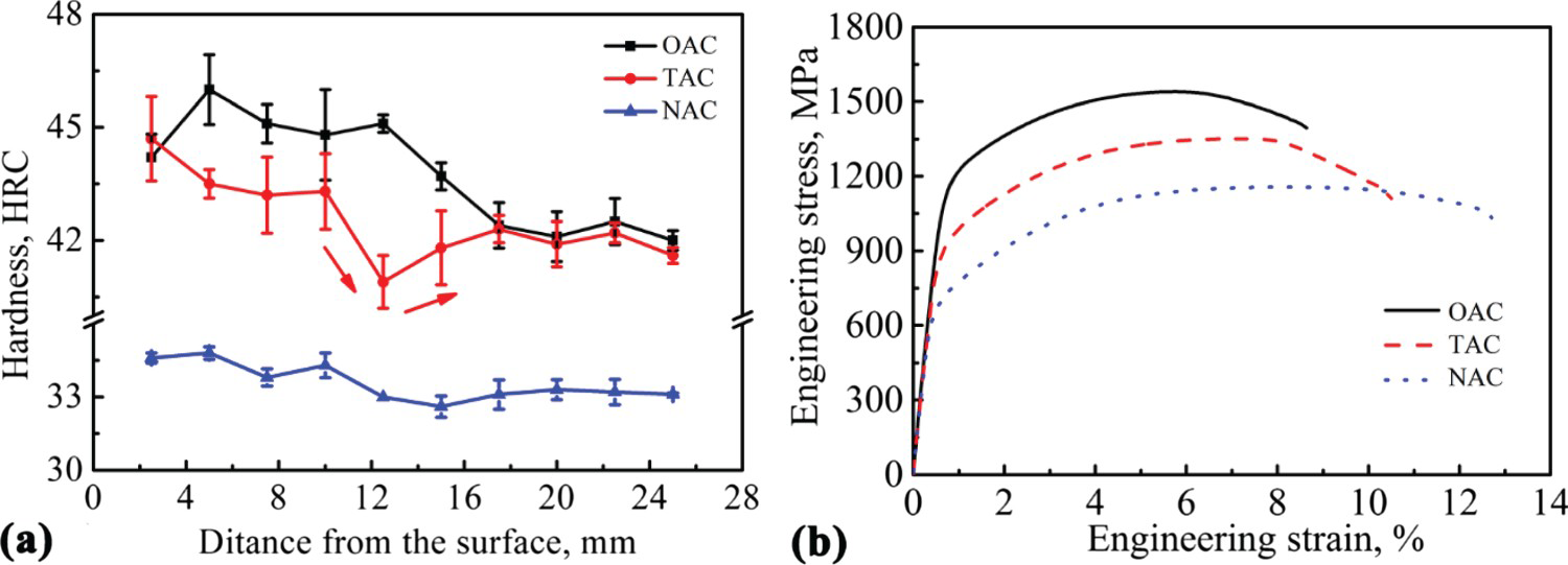
Mechanical properties of pearlitic steels at 5 mm position.
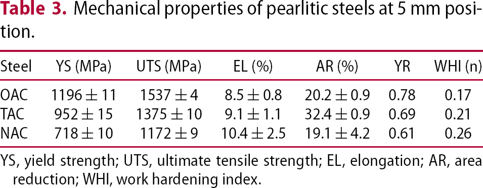
YS, yield strength; UTS, ultimate tensile strength; EL, elongation; AR, area reduction; WHI, work hardening index.
The hardness and strength of pearlitic steel are mainly controlled by the pearlite interlamellar spacing. Several investigators [6] reported that the strength and hardness of pearlite steels follow Hall-Petch relationship with respect to the pearlite interlamellar spacing at the ambient temperature. During the tensile process, the ferrite, as a soft phase, first undergoes plastic deformation and is accompanied by dislocation propagation and slip in ferrite [6]. In pearlitic steels with relatively large pearlite interlamellar spacing, the dislocations in wide ferrite were easy to multiply and slip, which resulted in the pile-ups of dislocations at the interfaces between ferrite and cementite. The increase in pile-ups resulted in the localised stress concentration which promoted the formation of large plastic deformation and micro cracks; thus, the steel with large pearlite interlamellar spacing possessed a low tensile strength [8,30,31]. Therefore, by comparing the properties of the three kinds of pearlitic steels treated by different heat treatments, the steel acquired from direct accelerated cooling after rolling obtained a thinner pearlite interlamellar spacing which possessed a relatively higher hardness and strength.
The pearlite interlamellar spacing of the steel was refined by accelerating the cooling rate after rolling, and the hardness and strength of the pearlitic steel were improved. Shortening the air cooling time after rolling increased the surface hardness of the steel. Furthermore, the sharp decrease in hardness was effectively avoided by conducting accelerated cooling twice after rolling.
Wear properties
The specimens at 5 mm below the surface for each steel treated by the heat treatments (OAC, TAC, and NAC) were selected to investigate the wear behaviours and microstructure evolution of pearlitic steel. The corresponding specimens were named 1500, 1300, and 1100 MPa grade steels, respectively. The worn surfaces of the steel under different wear time all contained numbers of grooves with different depth, as shown in Figure 4(a–c). In addition, the pile-ups with different height were observed at the verge of the worn surface, especially under the wear time of 180 min, as marked in Figure 4(c), which were mainly due to the deformation and accumulation of the surface matrix along the wear tangential direction during the wear progress. In Figure 4(d), with the increase in wear time from 60 to 180 min, the scar depths gradually increased while the curves became smoother. Besides, the scar depths were increased by 40.2 and 108.3% for the steels with wear time of 120 and 180 min, respectively.
Under the load of 100 N, the three-dimensional worn surface of 1500 MPa grade steel with different wear times: (a) 60 min, (b) 120 min, and (c) 180 min; (d) wear scar geometric profiles.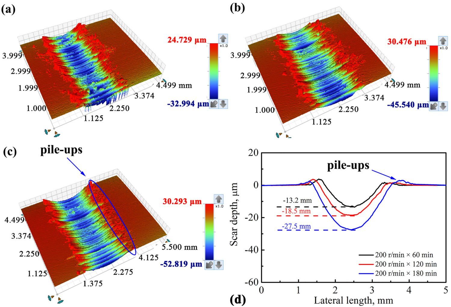
Under the load of 100 N, the three-dimensional worn surface and the wear scar geometric profiles of the 1500 MPa grade steel with different rotational speed are shown in Figure 5. Compared with the worn surface of the steel under the condition of 200 rev min−1 × 180 min in Figure 4(c), the worn surfaces were smoother with the increase in rotational speed, as shown in Figure 6(a,b). The wear scar geometric profiles in Figure 5(c) showed that the wear scar depth was 28.0 μm under 400 rev min−1 × 90 min, which was similar with that of the steel under 200 rev min−1 × 180 min. Meanwhile, when the rotational speed increased to 600 rev min−1, the scar depth of the steel reached up to 167.9 µm, which was 5.1 and 5.0 times higher than that of the steels under 200 rev min−1 × 180 min and 400 rev min−1 × 90 min, respectively.
Under the load of 100 N, the three-dimensional worn surface of the 1500 MPa grade steel with different rotational speed: (a) 400 rev min−1 × 90 min and (b) 600 rev min−1 × 60 min; (c) the wear scar geometric profiles.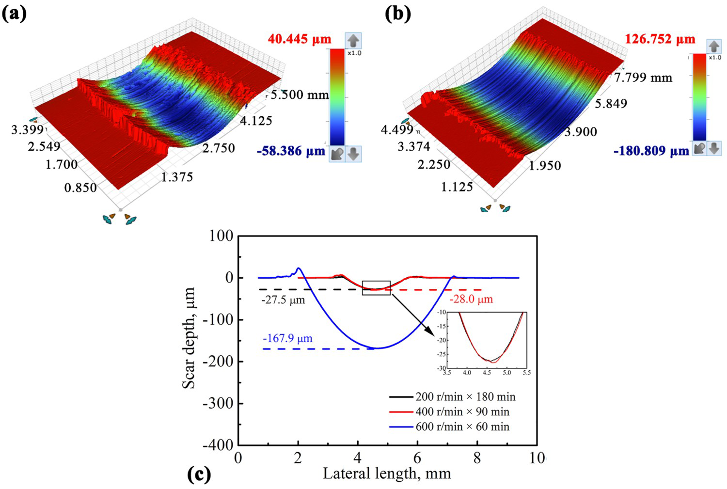
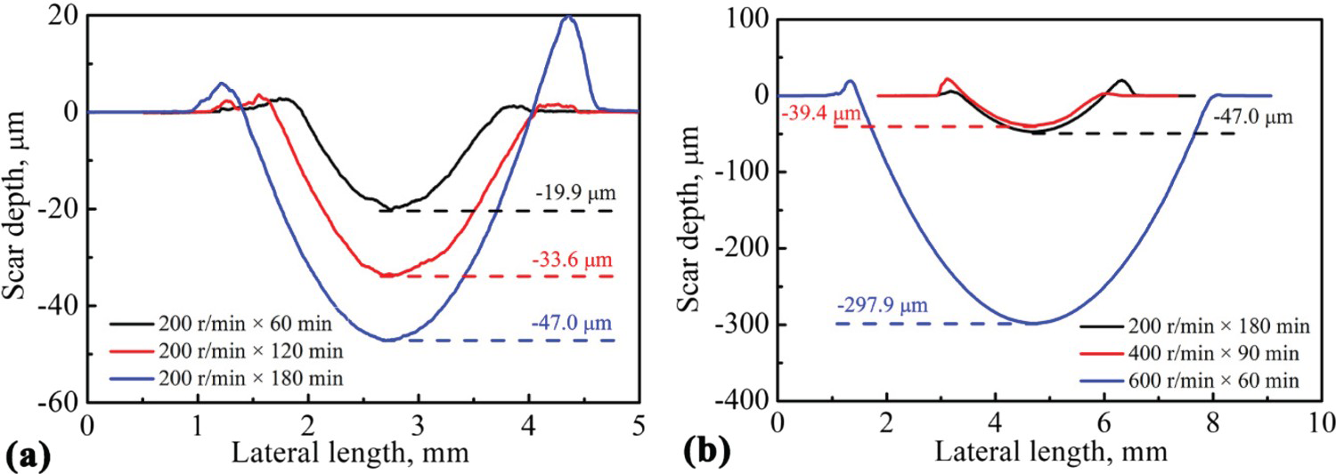
The wear scar geometric profiles of 1300 and 1100 MPa grade steels under different wear conditions are shown in Figures 6 and 7, respectively. Similar with the curves in Figure 4(d), the scar depths of 1300 MPa grade steel under the rotational speed of 200 rev min−1 increased with the prolonged wear time. The scar depths of 1300 MPa grade steel were higher than that of 1500 MPa grade steel under the same wear time, as shown in Figure 6(a). Both of the scar depths of 1300 MPa steel under 200 and 400 rev min−1 were observably less than that under 600 rev min−1. But a special phenomenon was that the scar depth of the steel under 400 rev min−1 was similar to that under 200 rev min−1, as shown in Figure 6(b). For the scar depths of the 1100 MPa grade steel (Figure 7), the scar depths were increased by 136.2% with the increase in wear time from 60 to 180 min under the rotational speed of 200 rev min−1, and the scar depths were all greater than that of 1500 and 1300 MPa grade steels. Besides, the scar depth variations for the 1100 MPa grade steel under different rotational speed had a similar tendency to that in Figure 5(c) and Figure 6(b), wherein the wear depths of the steel at the rotational speeds at 200 and 400 rev min−1 were similar but lower than that at 600 rev min−1, as shown in Figure 7(b).
Wear scar geometric profiles of 1300 MPa grade steel under different wear condition: (a) under different wear time and (b) under different rotational speed. Wear scar geometric profiles of 1100 MPa grade steel under different wear condition: (a) under different wear time and (b) under different rotational speed.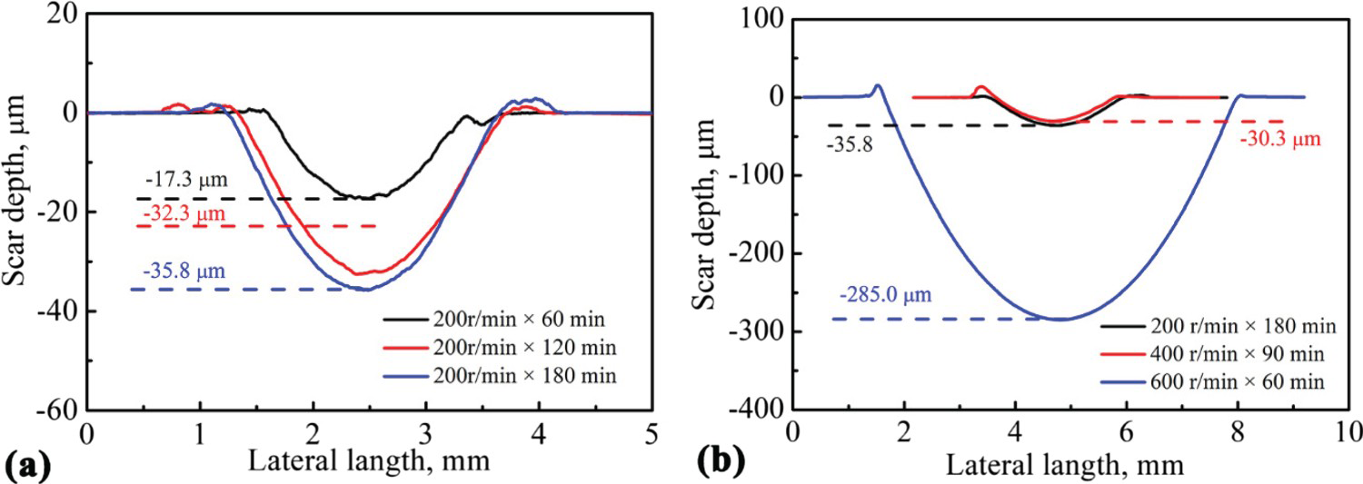
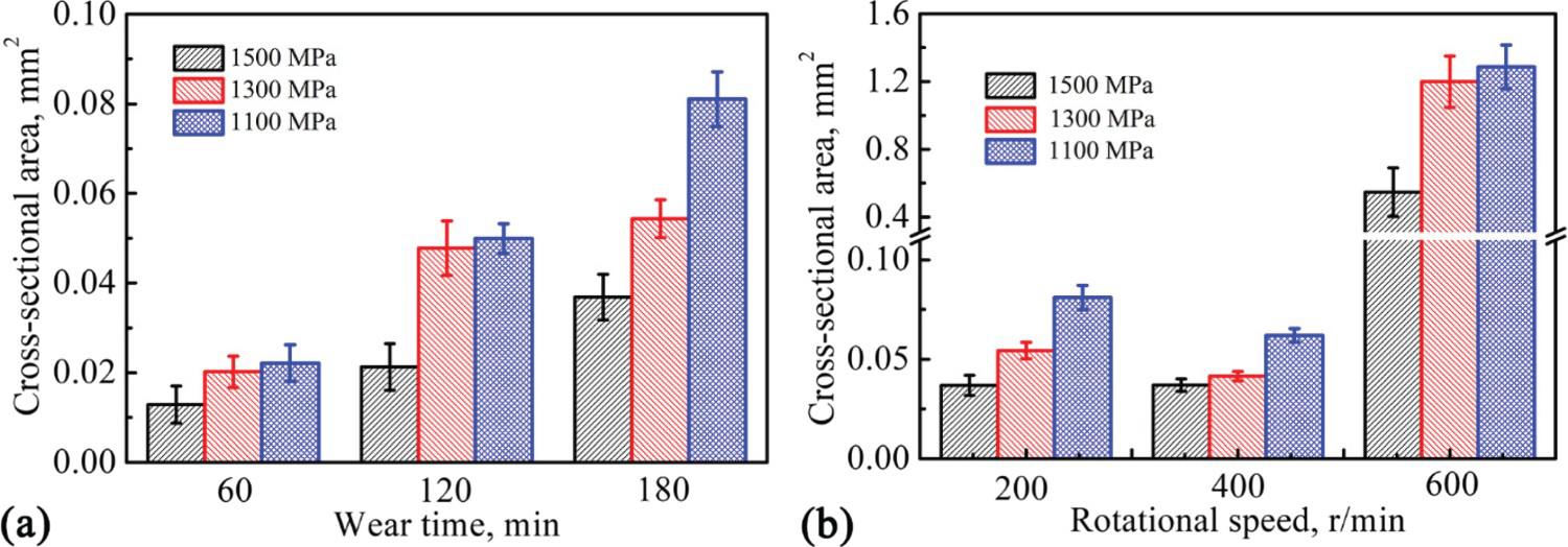
The cross-sectional areas of the pearlitic steel with different strength under different wear conditions were statistically analysed, and the results are shown in Figure 8. With the increase in hardness and strength of pearlitic steel, the wear resistance increased, whereas the cross-sectional areas decreased. Thus, the pearlitic steels with fine pearlite interlamellar spacing exhibit high mechanical properties and excellent wear resistance. Modi and Porter [5,6,8] have demonstrated that the multiplication and pile-ups of dislocations in ferrite and the interface between ferrite and cementite were not easy to form, which restrained the formation of micro-cracks during the wear progress. Moreover, Equation (4) [32] confirmed that the finer pearlite interlamellar spacing the pearlitic steel possesses, the smaller the thickness of cementite is. The cementite with fine thickness can withstand a high degree of bending and even plastic deformation before fracture [33], and the pearlitic steels with refined microstructure have good wear resistance.
The cross-sectional areas of the pearlitic steel with different strength under different wear conditions: (a) under different wear time with the rotational speed of 200 rev min−1 and (b) under different rotational speed with the same number of revolutions.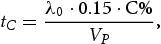
In different kinds of grade steels, the scar depths under the wear condition of 200 rev min−1 × 180 min and 400 rev min−1 × 90 min were not only close to but also significantly less than the scar depth of the steel under 600 rev min−1 × 60 min. The microstructure evolution of 1500 MPa grade pearlitic steel under different wear conditions were analysed in detail and the wear mechanism under the special wear condition of 400 rev min−1 × 90 min was investigated.
The changes of worn morphology and microstructure evolution in cross-section
Under the rotational speed of 200 rev min−1 with different wear time, the SEM images of the worn morphologies for 1500 MPa grade steel are shown in Figure 9. The morphological photographs illustrated that the wear surfaces were mainly composed of deposited oxide and peeling layer, and the wear mechanism was mainly dominated by oxidation wear and adhesive wear mechanisms [34,35]. Many studies have pointed out that the oxides covered on the worn surface are mainly Fe3O4 and Fe2O3, and the formation of oxides can effectively reduce the friction coefficient, thereby slowing the wear rate [10,19,34,35]. In addition, during the wear process, the local matrix peeled off along the direction of wear, thereby forming the scaly texture, as shown in Figure 9(c).
SEM images of the worn morphologies for 1500 MPa grade steel under different wear conditions: (a) 200 rev min−1 × 60 min, (b) 200 rev min−1 × 120 min, and (c) 200 rev min−1 × 180 min.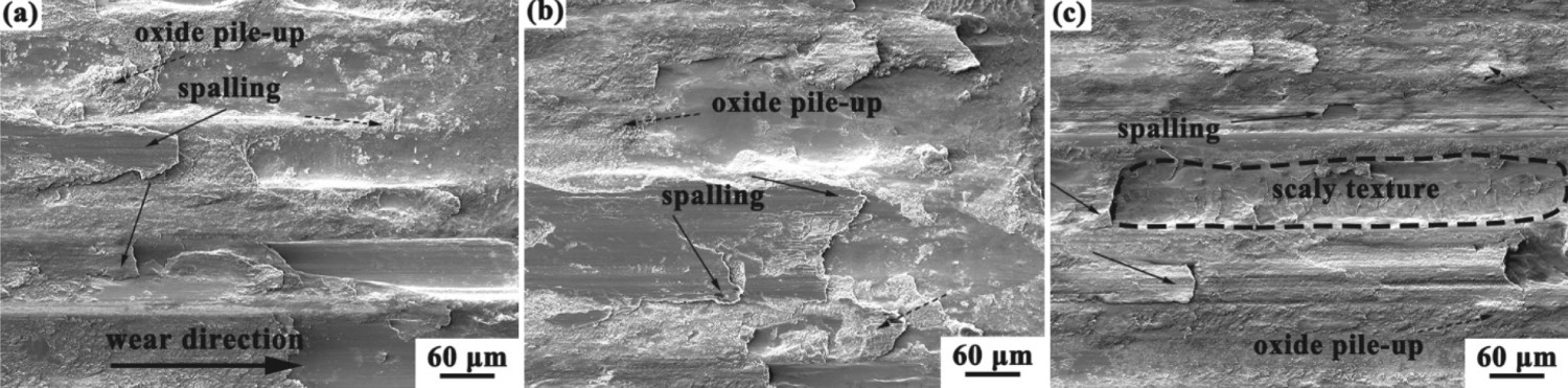
The microstructure observed on the cross-section of the 1500 MPa grade pearlitic steel tested at 200 rev min−1 with different wear time are shown in Figure 10. The SEM images in Figure 10 demonstrated that the microstructures of the steel tested at different wear time were all deformed along the wear direction. The thicknesses of the deformed layers were 29.9, 28.7, and 27.6 µm with wear time of 60, 120, and 180 min, respectively. Although the thickness of the deformed layer was slightly reduced as the wear time increased from 60 to 180 min, the changes were relatively small, as shown in Figure 10(a, c, and e). The contact surface increased with the increase in wear time, and then the contact stress applied on the surface of the specimen decreased, which induced a lower depth of the deformation. In addition, the local microstructures at high magnification showed that the typical pearlitic microstructures in the subsurface layer had disappeared as well as the fractured cementite arranged along the tangential direction of the wear, as shown in Figure 10(b, d, and f). Many researchers have shown that the cementite can partially re-dissolve into the matrix during the severe deformation process [18,32,37]. Therefore, the small cementite particles in severe deformed layer uniformly distributed in the matrix as seen in Figure 10(b). The deformed and fractured cementite tended to be parallel to the worn surface, which can increase the contact area between the cementite and the friction pair, thereby slowing the further wear of the matrix [33].
SEM images of subsurface across the depth of worn surface layers of 1500 MPa grade steels after wear testing at: (a) 200 rev min−1 × 60 min; (c) 200 rev min−1 × 120 min; (e) 200 rev min−1 × 180 min. High-magnification images of the area marked by dashed rectangle in (a), (c), and (d) are shown in (b), (d), and (f), respectively.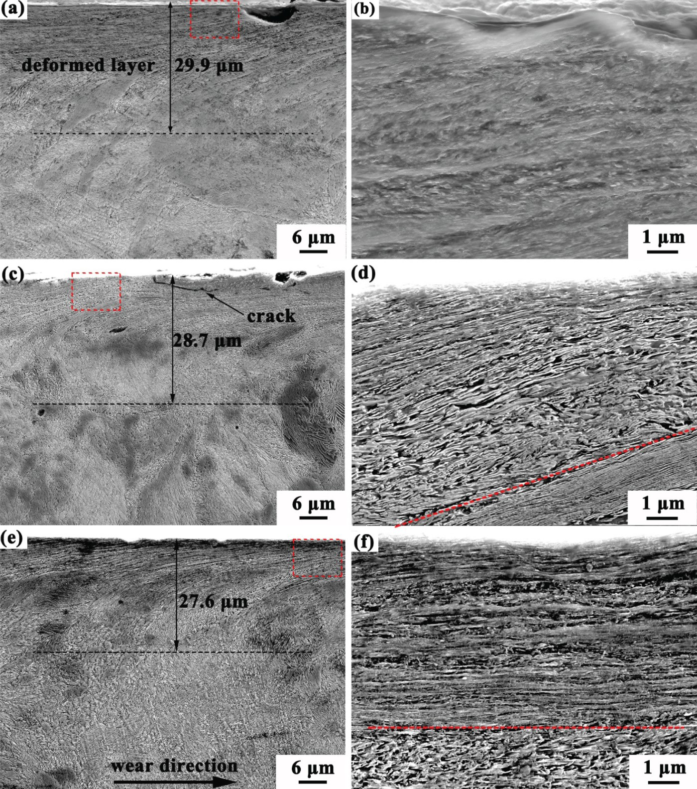
In order to compare with the microstructure observed on the cross section of 1500 MPa grade steel tested at 200 rev min−1 × 180 min, Figure 11 shows the SEM images of subsurface for 1300 and 1100 MPa grade steels tested at the same wear condition. The thicknesses of deformed microstructures were 31.4 µm for the 1300 MPa grade steel and 45.2 µm for the 1100 MPa grade steels, as shown in Figure 11(a,c), respectively. The thickness of the deformed layer increased with the decrease in strength. The yield strengths of the three kinds of steels at 5 mm were 1196, 952, and 718 MPa. Therefore, the steel with low hardness and yield strength produced large deformed layer under the same conditions.
SEM images of subsurface across the depth of worn surface layers of steels after the wear testing at 200 rev min−1 × 180 min (a) 1300 MPa grade steel and (c) 1100 MPa grade steel. High-magnification images of the area marked by dashed rectangle in (a) and (c) are shown in (b) and (d), respectively.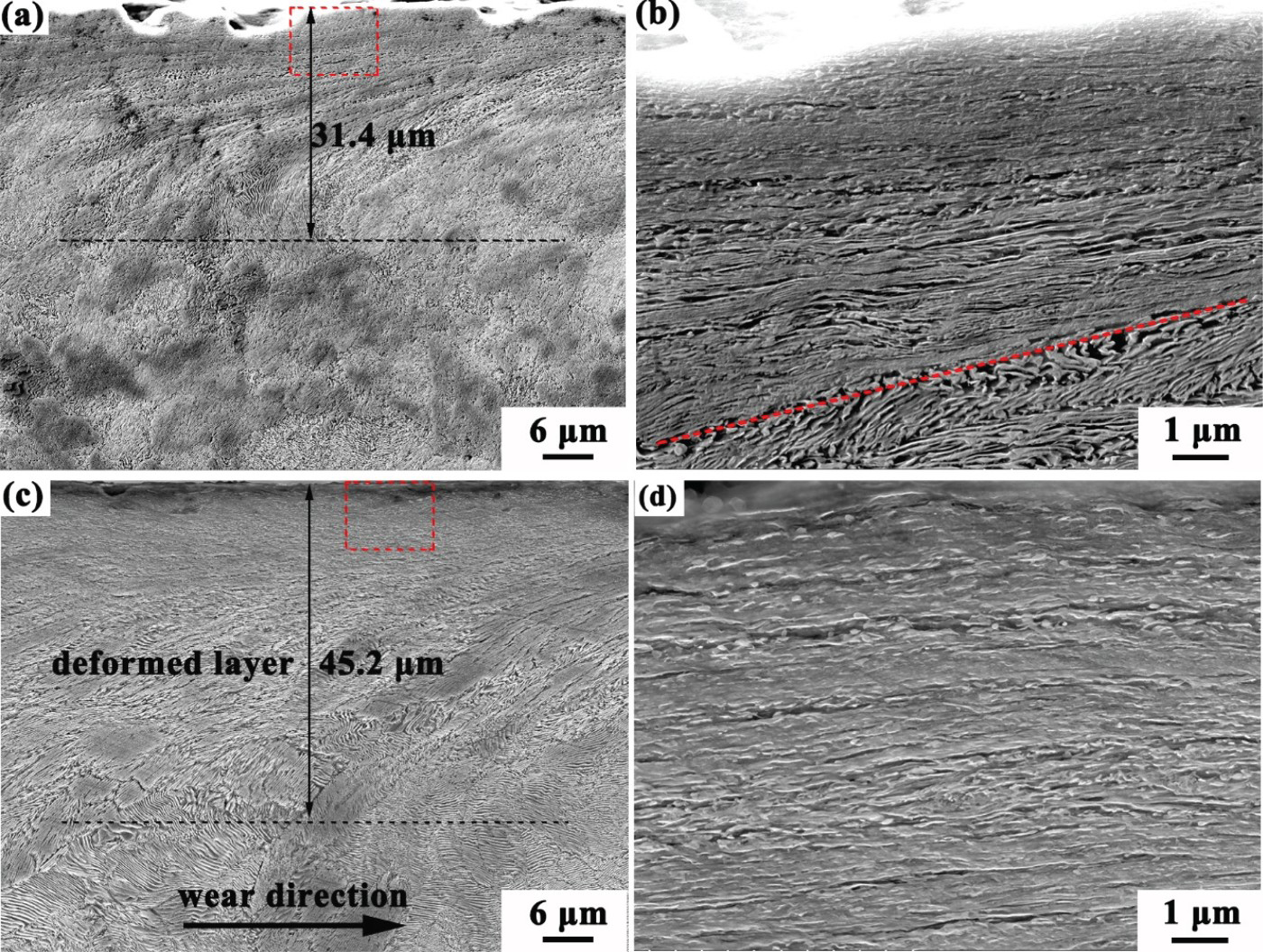
Figure 12 shows the worn morphologies of 1500 MPa grade steel tested at 400 rev min−1 × 90 min and 600 rev min−1 × 60 min. A large smooth area was observed, and no accumulation of oxide on the worn surface were detected on the smooth area, as shown in Figure 12(a,b). In addition, severe wear area with numerous cracks can be observed in Figure 12(c). In this area, the matrix was sharply deformed along the wear direction, and many crushed fragments were accumulated at the edges of ploughing.
SEM images of the worn morphologies for 1500 MPa grade steel tested at (a) 400 rev min−1 × 90 min, (b) and (c) 600 rev min−1 × 60 min.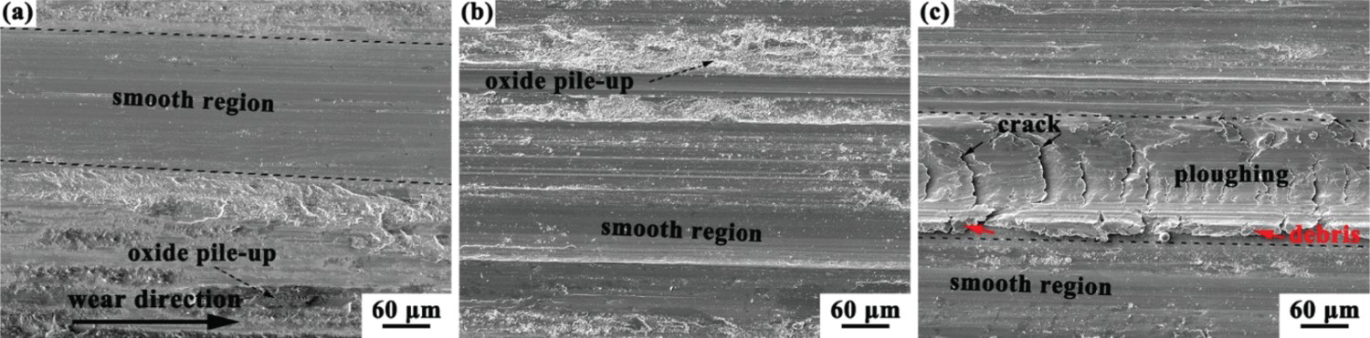
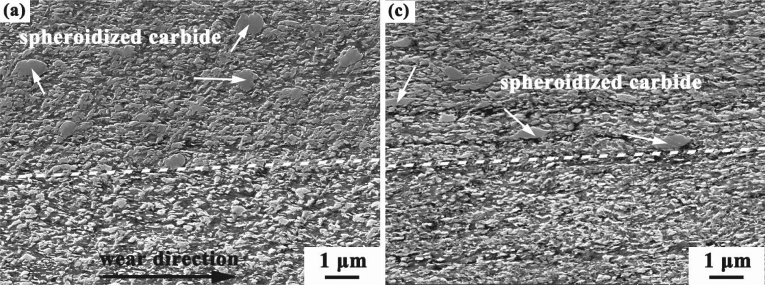
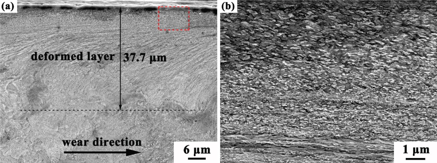
Compared with the microstructure of the subsurface of the steel tested at 200 rev min−1 × 180 min, the microstructure of the steel under 400 rev min−1 ×90 min contained not only a 35.2 µm-thick deformed layer but also a 9.8 µm-thick spheroidal layer, as shown in Figure 13(a). The fractured cementite was smaller than the spheroidal carbide and was uniformly distributed in the beneath region in the spheroidal layer. The special spherical carbides with a diameter of about 0.38 µm is shown in Figure 13(b). To analyse the evolution of microstructure of the steel under the wear condition of 400 rev min−1 × 90 min, the stitched SEM images of the microstructures are shown in Figure 13(c). The first layer was a spheroidal layer with spherical carbides, and the adjacent layer where the fractured cementite arranged along the tangential direction of the wear direction was severely deformed. When the distance from the worn surface increased, the deformed microstructure flowed along the direction of the shear force, and some cementite tended to kink. The spherical layers with spherical carbides were observed from the SEM images of subsurface for the 1300 and 1100 MPa grade steels, as shown in Figure 14. The deformed layer was also observed from the subsurface of the 1500 MPa grade steel tested at 600 rev min−1 × 60 min, but the spherical carbide similar to those in Figures 13 and 14 were not observed, as shown in Figure 15.
SEM images of subsurface across the depth of worn surface layers of 1500 MPa grade steels tested at 400 rev min−1 × 90 min. High-magnification images of the area marked by dashed rectangle in (a) is shown in (b). The SEM images of subsurface across the depth of worn surface layers of (a) 1300 MPa grade steel and (b) 1100 MPa grade steel tested at 400 rev min−1 × 90 min. The SEM images of subsurface across the depth of worn surface layers of 1500 MPa grade steel tested at 600 rev min−1 × 60 min. High-magnification images of the area marked by dashed rectangle in (a) is shown in (b).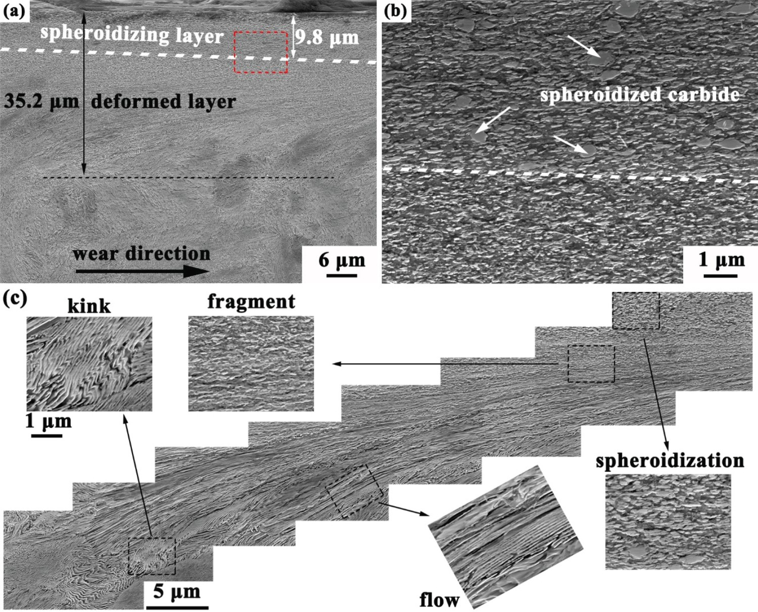
Zhou et al. [10] studied the effects of slippage on rolling contact of pearlitic wheel–rail steels, and pointed that the damage of wear zone was transformed from mild to severe with the increased slippage. Under low slippages, the wear loss increased slowly with increased slippage. When the slippage exceeded 2.38%, the wear loss of the steel increased drastically and exhibited severe wear. The results were similar to the test result in Figure 8(b). Many studies reported that the pearlitic microstructure in the steel deformed, fractured, and flowed along the wear or rolling directions during the cold and wear processes [18,36–38]. The pearlitic steels with different components were cold rolled, followed by annealing processes with different holding time and then the evolution of microstructures was studied by Fu et al. [38]. They pointed that the pearlite microstructure was gradually deformed and fractured with increased deformation amount, and the deformed and fractured cementite were spherised after the annealing treatment at different times. During the deformation process, the deformation energy storage was accumulated in the cementite and the increase of deformation energy storage reduced the thermal stability of cementite [39]. Besides, the multiplication and pile-ups of dislocations at the interface between the ferrite and cementite promoted the formation of local large strain area. The increase in dislocations provided more channels for the diffusion of carbon atoms. During the wear process, the pearlitic steel not only had a large deformation in the contact surface area but also generated heat in the vicinity of the contact surface, considerably increasing the temperature. Compared with the steel under the wear condition of 200 rev min−1 × 180 min, the deformation rate of the surface matrix was higher at 400 rev min−1 × 90 min and more heat was generated between the contact surfaces. Therefore, under the wear condition of 400 rev min−1 × 90 min, the spheroidisation of deformed and fractured cementite in the subsurface was promoted by deformation and high temperature, which slowed down the wear rate. For the steel subjected to 600 rev min−1 × 60 min, the temperature between the friction pairs was higher. Besides, the wear surface morphologies included the smooth areas, oxide accumulation regions, cracks, and grooves which showed that severe wear occurred, as shown in Figure 12(b and c). In these conditions, the wear rate of the steel was much higher than the surface hardening rate such that the scar depth of the steel under the wear condition of 600 rev min−1 × 60 min was significantly greater than those of steels under 200 rev min−1 × 180 min and 400 rev min−1 × 90 min.
Conclusions
Reducing the air-cooling time and increasing the cooling rate after rolling effectively refined the pearlite interlamellar spacing and increased the hardness and strength. Twice accelerated cooling process after rolling retarded the coarsening of centre pearlite interlamellar spacing and then increased the centre hardness of pearlitic steel. Under the same wear time, pearlitic steel with high hardness and strength exhibited improved wear resistance. The wear amount of the pearlitic steel under the wear condition of 200 rev min−1 ×180 min was the same as that under 400 rev min−1× 90 min, but both steels had obviously less wear amount than that under 600 rev min−1 × 60 min. Under different wear conditions, the cross-sectional microstructures with fractured cementite were all deformed, and the typical pearlitic structure disappeared. Meanwhile, under the wear condition of 400 rev min−1 × 90 min, the spheroidisation of deformed and fractured cementite in the subsurface was promoted by deformation and high temperature and then spherical layers with spherical carbides formed in the subsurface, which slowed down the wear rate.
Footnotes
Disclosure statement
No potential conflict of interest was reported by the authors.