
Abstract
An intercritical annealing pre-treatment was added before the conventional two-step heat treatment process, and the effect of the isothermal bainitic transformation (IBT) time on the steel's microstructure and mechanical properties were investigated. The microstructure was investigated using scanning electron microscopy, transmission electron microscopy, and X-ray diffraction, while the mechanical properties were evaluated using tensile testing. The microstructure of the three-step hot-dip galvanised transformation induced plasticity (TRIP) steel consists of ferrite, bainite, retained austenite, and martensite. The mechanical properties of the steel after the three-step heat treatment process are excellent, with a tensile strength above 770 MPa and elongation above 29%. The effect of IBT time on the mechanical properties was insignificant because the intercritical annealing pre-treatment increases the bainitic transformation rate.
Introduction
Transformation induced plasticity (TRIP) steels are ideal for lightweight automotive applications due to their combination of high strength and good ductility [1]. This combination of strength and ductility is produced by the TRIP effect: composite strengthening provided by a multiphase microstructure, and solid solution strengthening provided by alloying additions such as C, Si, and P [2–4]. The multiphase microstructure is usually generated by a standard, two-stage heat treatment [2,5]. The first stage is intercritical annealing, and the second stage is bainite transformation. Bainite transformation is central to the processing of TRIP steels [6] because during the bainite transformation stage, carbon redistributes from the bainitic ferrite to the surrounding austenite, leading to stabilisation of the remaining austenite at room temperature [2,7].
Car materials must be more durable, for both safety reasons and the increasing demand for greater environmental friendliness. Using hot-dip galvanised steel sheet enables car manufacturers to maintain the structural integrity and safety of the vehicle and to satisfy consumer demands for vehicle durability [8]. However, to use the continuous galvanising process to produce TRIP steels, some challenges must be resolved.
First, the selective oxidation of the alloying element Si during annealing prior to galvanising can result in poor reactive wetting and unacceptable bare-spot defects in the Zn coating [9]. Improved reactive wetting has been obtained when galvanising TRIP steels by either partially or completely replacing Si with Al and P [3,6,10–12].
Second, the bainite transformation time of the hot-dip galvanising production line is short (less than 30 s), resulting in poor mechanical properties of the steel, e.g. when the bainitic time is 20 s, the elongation below 24%, when the bainitic time is 10 s, the elongation below 20% [13]. Depending on the bainitic hold time, various mixtures of bainite, martensite, and retained austenite can be found in the microstructure after quenching [2]. When the bainitic hold time is short, martensite is expected to form by the transformation of austenite with a low carbon content after the bainitic transformation; the shorter the bainitic hold time, the greater the content of martensite and the lower the elongation of the TRIP steel. Improving the stability of the austenite after the bainite transformation can increase the fraction of the retained austenite and thus increase the elongation of hot-dip galvanised TRIP steels.
The stability of the retained austenite depends not only on its carbon content but also on the hardness of the surrounding phases and on the austenite grain size [8,14,15]. Sugimoto et al. [16] reported a kind of TRIP steel with an annealed martensite mixture and interlath-retained austenite, named TAM steel. Compared with the retained austenite in conventional TRIP steel, named TPF steel by Sugimoto, the stability of the retained austenite in the TAM steel is better due to the fine distribution of the interlath-retained austenite and the intermediate hardness of the annealed martensite. Sugimoto used a three-stage heat treatment to obtain the TAM steel; an austenitising stage was added before the standard, two-stage heat treatment [16].
The heat treatment of TAM steel can improve the stability of retained austenite, which suggests the treatment might be used in the process of hot-dip galvanised TRIP steel. However, there is a challenge: the hot-dip galvanised TRIP steel contains Al, and Al will significantly increase Ac3 [17]; increased Ac3 will make it hard to complete austenitising. Wei et al. [18] designed a low Si TRIP steel containing Al using partial austenitising; they obtained a TAM steel with a microstructure that consists of polygonal ferrite, bainite, annealed martensite, and retained austenite, and most of the retained austenite is fine interlath-retained austenite. Compared with the mechanical properties of the TRIP steel produced with the traditional, two-stage heat treatment, the TAM steel exhibits better elongation but has a slightly lower tensile strength [18,19]. Applying the process to the heat treatment of hot-dip galvanised TRIP steel may increase the elongation of the steel, solving the problem of low elongation.
In this work, a C–Mn–Al–P–Nb hot-dip galvanised TRIP steel was designed using a three-step heat treatment process: an intercritical annealing pre-treatment followed by the normal, two-step hot-dip galvanised TRIP steel heat treatment. The microstructure and mechanical properties of the steel were studied. The influence of the intercritical annealing pre-treatment on the bainitic transformation of the steel was studied with dilatometry.
Experimental procedure
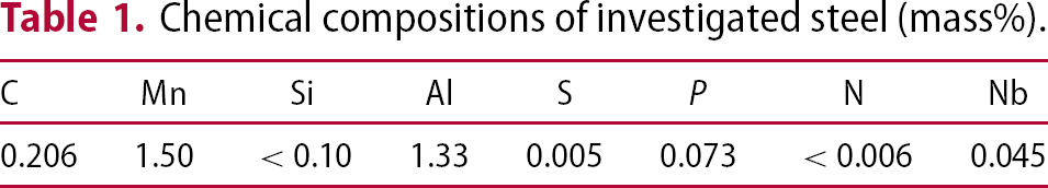
Chemical compositions of investigated steel (mass%).
The steel plates were heat treated in a Gleeble 3500 equipment, with rectangular specimens of 200 mm in length (rolling direction) and 50 mm in width. The normal two-step heat treatment follows directly after a pre-treatment: intercritical annealing at 900°C for 180 s, and then quenching to room temperature. This pre-treatment process will control the microstructure before the conventional two-step heat treatment and the microstructure consists of ferrite and martensite. Figure 1 shows a schematic illustration of the heat treatment cycle.
Schematic diagram of the entire heat treatment cycle.
Tensile specimens from the heat-treated samples were prepared with a dog-bone shape and a gauge length and width of 50 and 12.5 mm, respectively. Tensile tests were carried out in an MTS universal testing machine with a load range of 50,000 N. The cross head speed was maintained at 2 mm min−1.
The microstructures were studied by scanning electron microscopy (SEM) after conventional metallographic sample preparation and nital etching. Transmission electron microscopy (TEM) specimens were prepared by mechanical polishing and electropolishing in a twin-jet polisher using 5% perchloric acid solution. The TEM investigation was performed using a JEOL 2010 instrument, at an acceleration voltage of 200 kV.
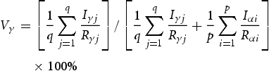
The volume fraction of retained austenite in the heat-treated samples was measured by X-ray diffraction (XRD) using Cu Kα radiation. Samples for XRD were prepared first by mechanical polishing, then by electropolishing at 15 V at room temperature, using an electrolyte consisting of 10 vol.-% glycerol, 20 vol.-% perchloric acid, and 70 vol.-% ethanol. The integrated intensity (I) of the (200) and (211) peaks of the body-centered cubic (bcc) structure and the (200), (220), and (311) peaks of the face-centered cubic (fcc) structure were determined using least-square fitting of a Pearson VII type function, and the volume fraction of retained austenite was calculated using the direct comparison method according to the following equation [20,21]:
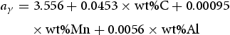
For the calculation of the carbon content of the retained austenite (Cγ), the lattice parameter  was determined using the fcc (220) diffraction peak. At room temperature, the lattice parameter of austenite depends upon the chemical composition as follows [22,23]:
 is the austenite lattice parameter in Å and
  ,
,  and
and  are the alloying concentrations of C, Mn, and Al, respectively. It is noteworthy that Si in this steel has a negligible effect on the lattice parameter of austenite [23].
Dilatometry was conducted using a DIL 805 instrument. Cylindrical specimens with 4 mm diameter and 10 mm length were used.
Results and discussion
Microstructure
Microstructure evolution during heat treatment
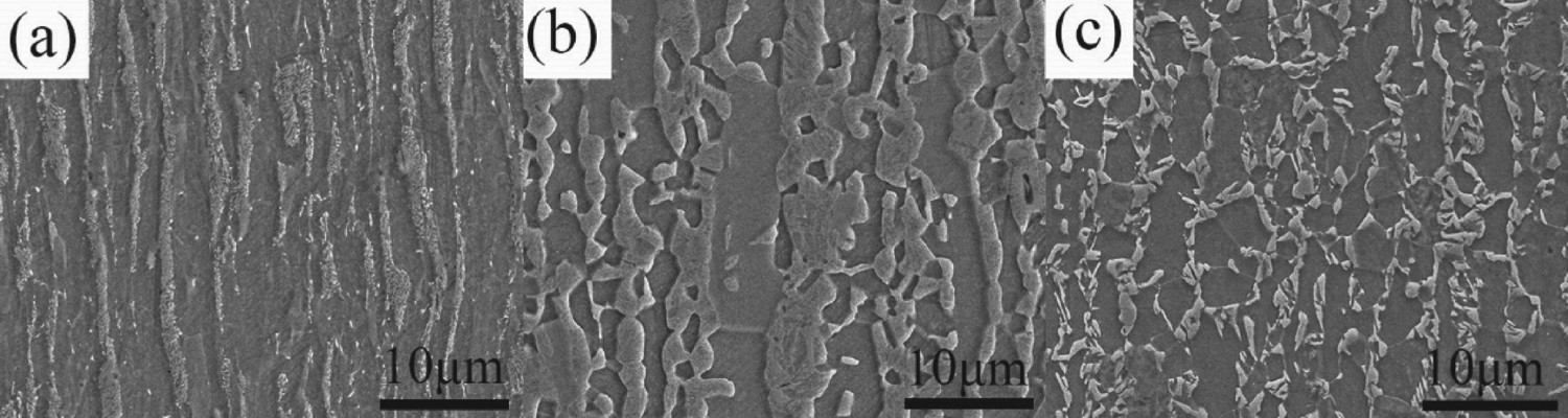
Figure 2 shows SEM micrographs of the steel at different stages. Figure 2(a) shows the initial microstructure of the steel; it consists of ferrite and pearlite. Figure 2(b) shows the microstructure after the intercritical annealing and quenching pre-treatment, consisting of ferrite and martensite, with the content of martensite The SEM micrographs of the steel at different stages: (a) as-received; (b) after the intercritical annealing pre-treatment; and (c) after the complete, three-step heat treatment with an isothermal bainitic transformation time of 20 s. . Figure 2(a,b) shows that during intercritical annealing, the austenite first nucleates and grows on the pearlite, then gradually expands to the ferrite region. The reason for this pattern is that pearlite is an enrichment zone of carbon and manganese, which are austenite-stabilising elements. Figure 2(c) shows the microstructure after the entire three-step heat treatment; the microstructure of the final steel when using the intercritical annealing pre-treatment consists of ferrite, banitie, and retained austenite/martensite, with the content of ferrite
  .
.
TEM was used to observe the retained austenite after the three-step heat treatment, which had an isothermal bainitic transformation (IBT) time of 20 s. Figures 3–5 show the TEM micrographs of the retained austenite.
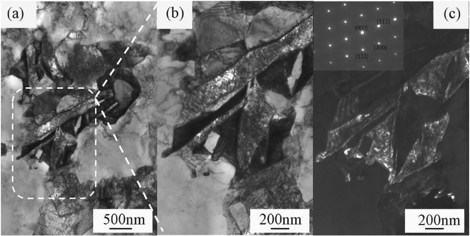
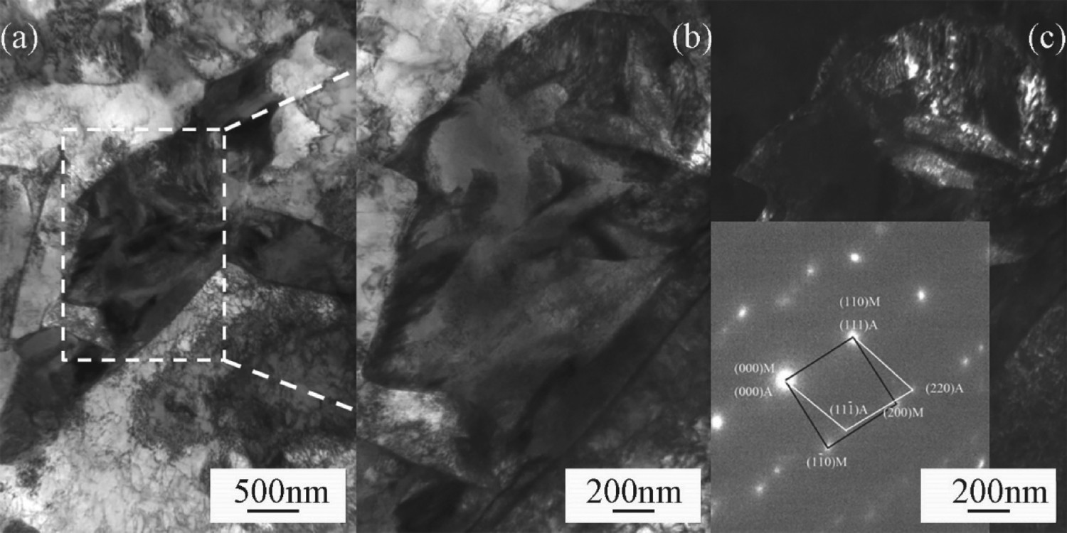
The block-retained austenite's (a) morphology, (b) bright field image, and (c) dark field image and selected area diffraction. The lath-retained austenite's (a) morphology, (b) bright field image, and (c) dark field image and selected area diffraction. The M-A island's (a) morphology, (b) bright field image, and (c) dark field image and selected area diffraction.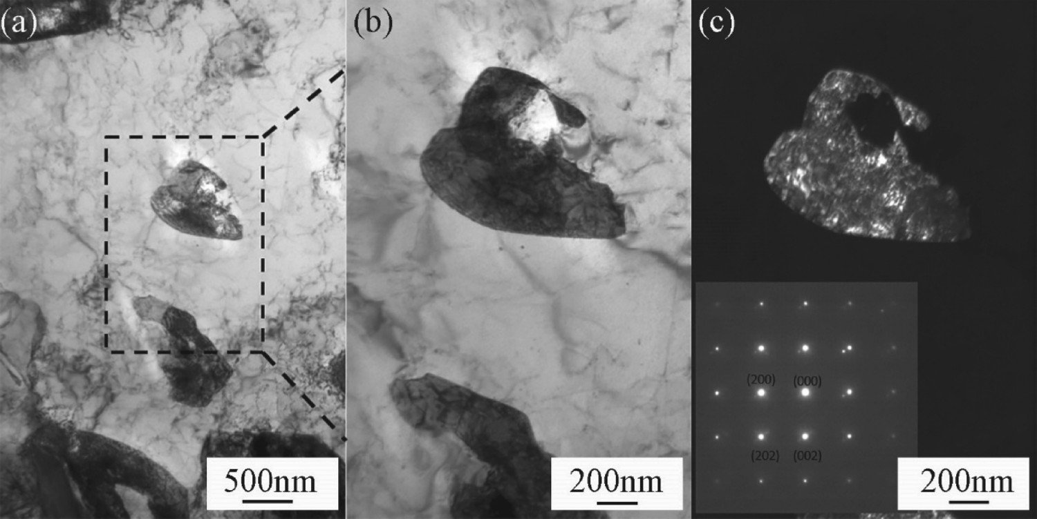
Block-retained austenite shown in Figure 3, retained austenite particles of less than 1 μm are isolated in the ferrite matrix or on the grain boundary, away from or adjacent to the bainite particles. A few dislocations and/or stacking faults are observed in some retained austenite islands.
Figure 4 shows the lath-retained austenite. The retained austenite appears on the previous martensite lath boundary obtained by the intercritical annealing pre-treatment (Figure 1). The grain size of lath-retained austenite is much finer than that of block-retained austenite: the width of lath-retained austenite particles is less than 0.2 μm.
In addition to those two kinds of retained austenite, a third is austenite that coexists with martensite, named an M-A island, as shown in Figure 5. An M-A island forms by the transformation of austenite with a low carbon content after the IBT. The too-short IBT time, an inherent characteristic of the hot-dip galvanised TRIP steel process, causes inevitable martensite in hot-dip galvanised TRIP steel.
The SEM and TEM observations show that the microstructure of the steel formed using an intercritical annealing pre-treatment consists of ferrite, bainite, retained austenite, and martensite. Retained austenite exists in three different morphologies: block-retained austenite, lath-retained austenite, and M-A islands. The ferrite around the lath austenite is called ‘annealed martensite’ in the literature. Compared with traditional TRIP steel, annealed martensite with interlath-retained austenite has added structure.
Influence of intercritical annealing pre-treatment on bainitic transformation
Figure 6(a,b) shows the dilatometry curves with and without the intercritical annealing pre-treatment, respectively. Figure 6(c) shows the degree of bainitic transformation at the two different conditions, as well as the derivative, to reflect the speed of bainitic transformation [24,25].
Dilatometry curves with different heat treatments: (a) curves with the intercritical annealing pre-treatment and (b) curves without the intercritical annealing pre-treatment. (c) Degree of bainitic transformation and rate of bainitic transformation.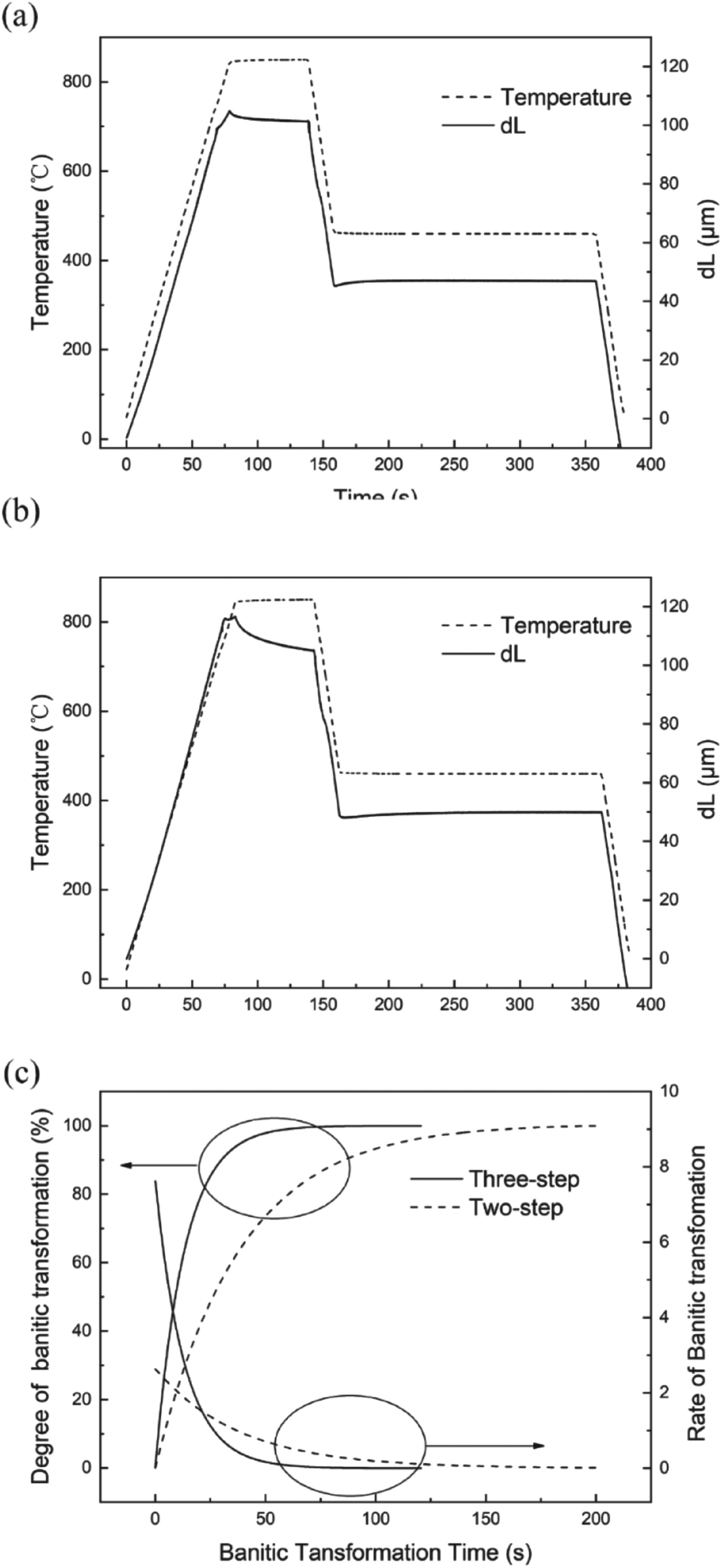
Figure 6(c) shows that the speed of bainitic transformation is fast in the initial stage. The sample with the intercritical annealing pre-treatment (named the ‘three-step’ process) has a higher speed than the sample without the intercritical annealing pre-treatment (named the ‘two-step’ process), especially during the first 20 s. For the sample with the intercritical annealing pre-treatment, most of the bainitic transformation (nearly 99%) occurs in the first 60 s; at 10 s, the bainitic transformation is at 53.6%, and at 30 s, the bainitic transformation is at nearly 90%. However, in the sample without the intercritical annealing pre-treatment, at 10 s, the bainitic transformation is at only 23.3%, and at 30 s, the bainitic transformation is at no more than 55%. These results show that the intercritical annealing pre-treatment can accelerate the bainite transformation, which is particularly significant for hot-dip galvanising. Hot-dip galvanising production lines usually cannot provide a long IBT time, so accelerating the bainitic transformation is useful to overcome the negative effects of a short bainite transformation time.
Influence of IBT time on microstructure
For TRIP steel, the fraction of retained austenite is important, and the influence of the heat treatment process on the retained austenite should be explored. Figure 7(a) shows the XRD patterns after the heat treatment for different IBT times, while Figure 7(b) shows the influence of IBT time on the fraction of retained austenite and its carbon content.
(a) XRD patterns of the steel samples with different IBT times and (b) volume fractions of retained austenite and carbon content at various times.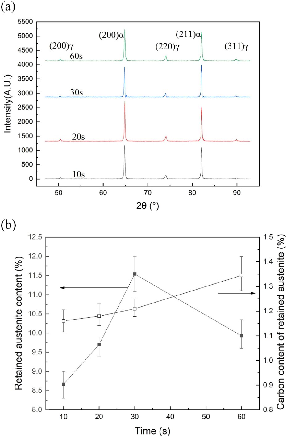
With increasing IBT time, the content of retained austenite and its carbon content show different trends. The content of retained austenite first increases and then decreases with increasing IBT time, whereas the carbon content simply increases with IBT time.
During the IBT holding time, the austenite partially transforms to bainite, and carbon which separates to the untransformed austenite. This explains the increased carbon content of the retained austenite.
If the carbon partitioning from the austenite is substantial, the austenite will not transform to martensite upon cooling, whereas, if the carbon partitioning is lower, the austenite will transform to martensite. If the IBT time is short, the bainitic transformation and concurrent carbon partitioning are not sufficient to stabilise the austenite. Hence, some metastable austenite will transform to martensite during the final cooling. This result explains why the retained austenite content increases with IBT time, when the IBT time is short. As the IBT time continues to increase, more and more austenite transforms to bainite, which results in a decrease in retained austenite. Hot-dip galvanising production lines usually cannot provide a long IBT time; thus, no previous studies have reported a decrease in austenite content [6,17,20].
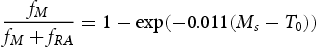
To further investigate how the IBT time influences the steel microstructure, the following formulas were combined with experimental results and used to evaluate the content of bainite and martensite. Equations (5) and (6) are from references [26] and [27,28], respectively:
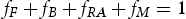


 ,
,  ,
,  , and
, and  represent the volume fraction of ferrite, bainite, retained austenite, and martensite, respectively;
 ,
,  ,
,  , and
, and  represent the carbon content of ferrite, bainite, retained austenite, and martensite, respectively;
 represents the temperature at which austenite starts transforming to martensite;
 represents the room temperature, assumed to be 20°C; and
 represents the manganese content (mass per cent, %) in the martensite, assumed to be 1.5 times as much as the manganese content of steel [29,30].
 was calculated in Microstructure evolution during heat treatment and has a value of 73%. The
  and
and  can be tested by XRD. The values of
  and
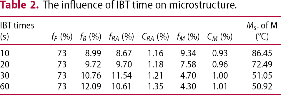
and  are 0.0219% and 0.03% [31], respectively. Table 2 summarises the calculated results.
The influence of IBT time on microstructure.
 (%)
(%) (%)
(%) (%)
(%) (%)
(%) (%)
(%) (%)
(%) . of M (°C)
With increased IBT time, the volume fraction of bainite gradually increased; more and more austenite transformed into bainite, while the portion of austenite that did not transform to bainite became further enriched in carbon. For various reasons, mainly the difference in carbon content, the stability of the austenite changes after the bainitic transformation, so in the final cooling stage, a martensitic transformation occurs in some of the austenite. As Table 2 shows, the content of martensite carbon increases, the Ms of martensite gradually decreases, and the martensite content decreases with increasing IBT time; however, the Ms of retained austenite is below room temperature at high carbon contents.
Mechanical properties
General mechanical properties
Figure 8 shows the values of elongation versus the tensile strength of the TRIP steel with the intercritical annealing pre-treatment (‘three-step’) and the reference steel without the intercritical annealing pre-treatment (‘two-step’). The data of the ‘two-step’ steel are from the literature [6,17,20], and the samples for compared have the same sample geometry, crosshead control and strain measurement benchmarking. As illustrated in Figure 8, the three-step steel has good mechanical properties with a tensile strength above 770 MPa and elongation levels above 29.00%, and has an excellent balance of strength and elongation; the product of strength and ductility is above 23 GPa%.
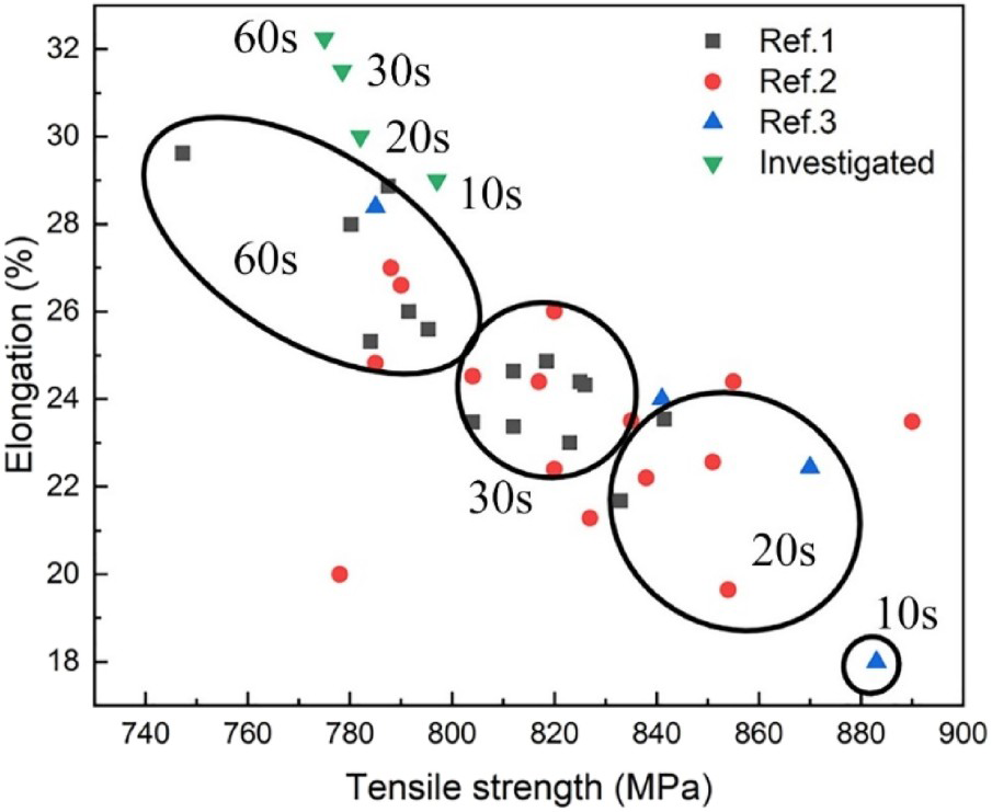
Figure 8 shows that a shorter IBT time increases the advantage in elongation that is gained with the three-step process. When the IBT time is 10 s, the elongation of the two-step steel [6] is only 18%, while the elongation of the three-step steel is 29%, an increase of 11%. When the IBT time is 10 s, the elongation of the two-step steel [6,17,20] is less than 24%, while the elongation of the three-step steel is 30%, an increase of 6%. It is worth noted that when the IBT time is 60 s, the increase of the elongation is no more than 4%.
Figure 9(a) is the tensile stress–strain curves of the steels, using data of two-step steel from the literature [6]. Three types of stress–strain curves were obtained, illustrating continuous yielding behaviour, discontinuous yielding behaviour without yield point elongation, and discontinuous yielding behaviour with yield point elongation. The three-step steel shows a discontinuous yielding behaviour without yield point elongation when the IBT time is short (IBT time is 10 and 20 s), and it shows a discontinuous yielding behaviour with yield point elongation when the IBT time is long (IBT time is 30 and 60 s). The two-step reference steel shows a continuous yielding behaviour when the IBT time is short (IBT time is 10 and 20 s), a discontinuous yielding behaviour without yield point elongation when the IBT time is 30 s, and a discontinuous yielding behaviour with yield point elongation when the IBT time is 60 s. In the case of continuous yielding, there is a large amount of martensite formed during final cooling, and the martensitic transformation will result in a high density of the mobile dislocations is generated in ferrite [32]. In the case of discontinuous yielding behaviour, the reason is that the low density of the mobile dislocations in ferrite. It is pointed in the literature [32] that the martensitic transformation of retained austenite can increase the number of the mobile dislocations in surrounding ferrite. If the stability of retained austenite is not high (the two-step reference steel with IBT time is 30 s), the retained austenite will transform to martensite at the early stage of deformation, the stress–strain curves show as discontinuous yielding without yield point elongation. However, if the stability of retained austenite is high (the three-step steel with IBT time is 30 and 60 s), it will transform to martensite in the middle and later stages of deformation, the stress–strain curves show as discontinuous yielding with yield point elongation.
(a) The tensile stress–strain curves and (b) n value versus Ture strain. The data for two-step steel are from reference [6].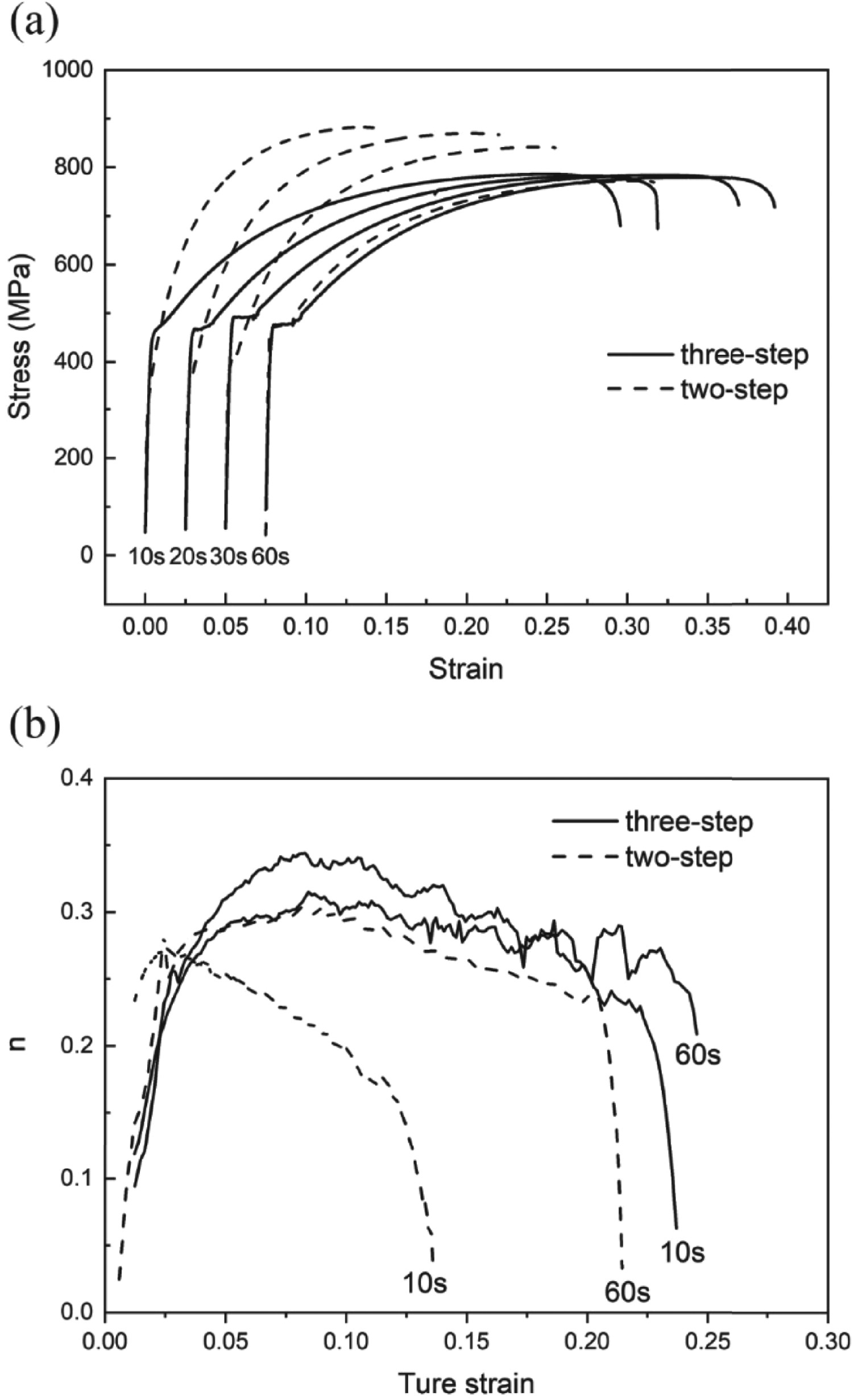
The strain hardening behaviour of the steel was studied for the samples with an IBT time of 10 and 60 s. The instantaneous strain hardening coefficient, n, was calculated using the following equation [33]:

 is the true stress, and
  is the true strain.
Figure 9(b) shows the change in the instantaneous n value during tensile testing. For the two-step steel, when the IBT time was 10 s, the n value increased greatly, reaching the maximum value at the beginning of straining, and then decreased continuously from a maximum value of 0.27. The n value characteristic of the sample is similar to those of dual-phase steel. In fact, dual-phase steels usually contain retained austenite; however, their stability is very low, and they easily transform to martensite [34].
For the three-step steel, however, even if the IBT time was only 10 s, the n value of the sample showed a different behaviour: the n value was low in the beginning but increased with strain and was kept high until fracture took place. The variation of the value of n with deformation indicates that the TRIP effect persists during the deformation process, which is the main reason for the good elongation of three-step steel. The TRIP effect persists during the deformation process because the retained austenite has varying stability. The block-retained austenite has low stability, and it is easy to produce the TRIP effect at the initial stage of deformation, while the lath-retained austenite has good stability and can produce the TRIP effect in the middle and late stages of deformation.
As we know that austenite transformation does not take place before matrix yielding [32,35,36], the work-hardening rate in the pre-yield regime depends on the dislocation density, grain size and morphology of the matrix(ferrite and bainite) [35]. In post-yield stage, the transformation of retained austenite leads to an increase in the macroscopic work-hardening rate after matrix yielding and continues to offset the decrease in the work-hardening rate in the ferrite and martensite phases up to the tensile strength [35]. The n values are affected significantly by the mechanical stability of the retained austenite [32].
The influence of bainitic hold time on mechanical properties
According to previous research [2,6,17,33], the bainitic hold time of the bainite transformation has become of primary importance in the processing of hot-dip galvanised TRIP steels. Depending on the bainitic hold time, various percentages of bainite, martensite, and retained austenite can be found in the microstructure after quenching. The intercritical austenite progressively transforms to bainite, bringing about a large stabilisation of austenite at room temperature at the expense of martensite. The main reason why the bainitic hold time influences the mechanical properties is that the time influences the volume fraction and stability of retained austenite.
Figure 10 shows the influence of the IBT time on the mechanical properties of the three-step steel. The IBT time has only a slight influence on strength; the tensile strength and the yield strength of all the samples are nearly 780 and 470 MPa, respectively, and the value of (yield strength)/(tensile strength) is nearly 0.60. And, the elongation of the sample also slightly increased with the IBT time; when the IBT time increased from 10 to 60 s, the elongation slightly increased from 29.00 to 32.25%.
The influence of the IBT time on the mechanical properties of steel processed using the three-step heat treatment process.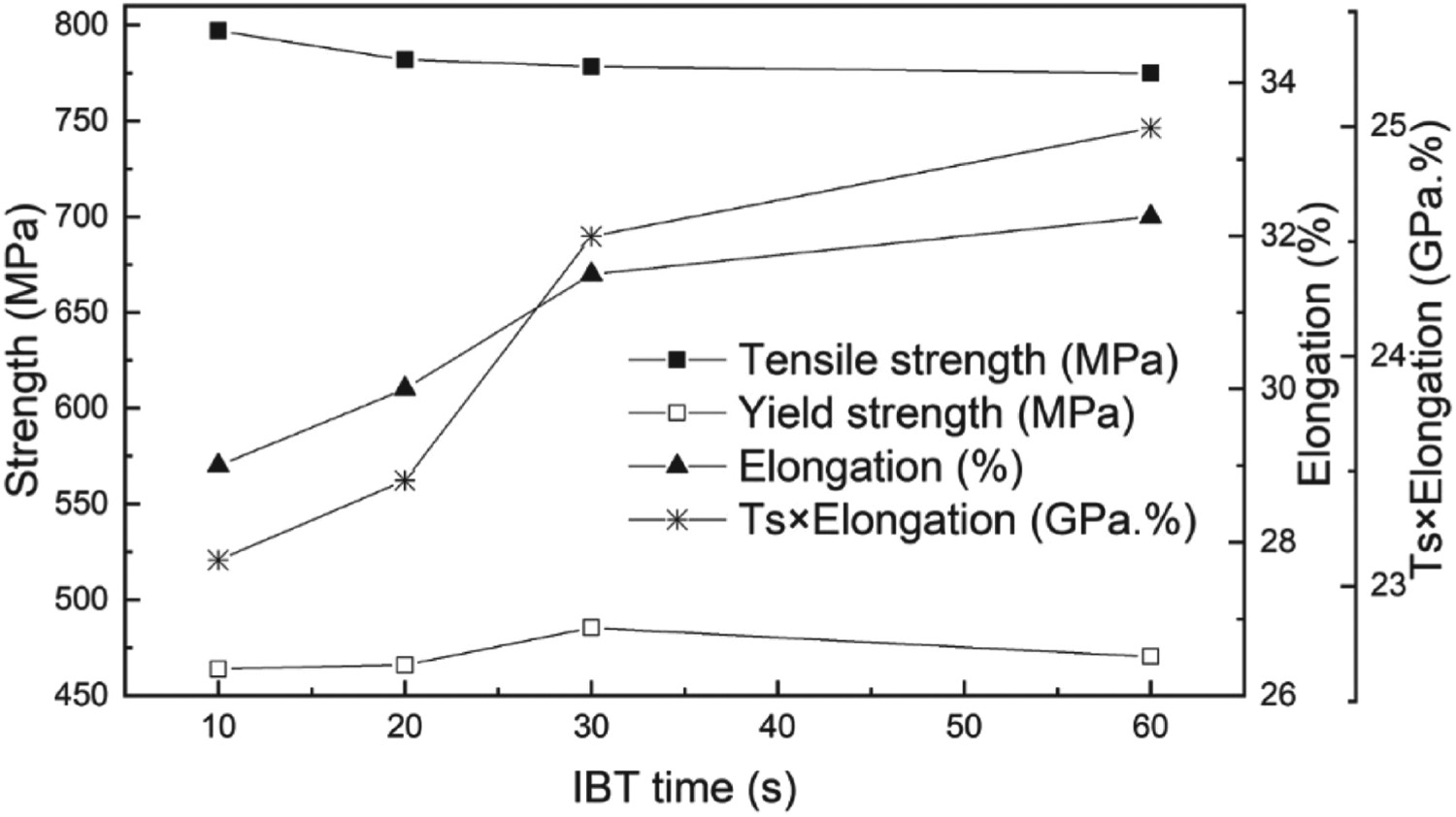
Compared with the two-step steel [6], the influence of the IBT time on the mechanical properties is insignificant. The reason may be that the IBT time has no significant effect on the volume fraction of retained austenite, as seen in Table 2. The IBT time has little effect on the volume fraction of retained austenite because the bainitic transformation takes place quickly, as seen in Figure 6. In addition, the interlath-retained austenite improves the stability of the austenite, thereby weakening the effect of martensite on performance – another reason why the IBT time has no significant effect on performance.
Conclusion
Adding an intercritical annealing pre-treatment before the conventional hot-dip galvanising process can significantly improve the overall elongation of hot-dip galvanised TRIP steel when the IBT time is short, i.e. 10 and 20 s.
The three-step hot-dip galvanised TRIP steel, with an added intercritical annealing pre-treatment before the conventional hot-dip galvanising process, speeds up the bainitic transformation, which reduces the effect of the IBT time on the final microstructure and results in a sufficient amount of stable retained austenite at a relatively short IBT time.
The three-step steel has better strain hardening behaviour than conventional two-step steel. The n value of the three-step steel remains stable during deformation because of the different stabilities of the retained austenite. The block-retained austenite has low stability, and the lath-retained austenite has good stability.
Footnotes
Acknowledgements
Wei Ding as a visiting researcher in Tsinghua University and Wei Ding thanks the PTMD group of Tsinghua University for their guidance and assistance in the writing and discussion of this article.
Disclosure statement
No potential conflict of interest was reported by the authors.