
Abstract
The paper aims to research the effect of rare earth elements on the carbonitriding layer of titanium alloy by establishing a theoretical model between rare earth concentration and atomic diffusion efficiency. It shows that adding rare earth can not only refine the discharge holes, but also reduce surface cracks, which significantly improve the surface quality of the strengthening layer. It is also found that an appropriate amount of rare earth can greatly increase the growth rate of the carbonitriding layer and carbon content near the surface. Furthermore, compared with the conventional plasma electrolytic carbonitriding treatment, adding 2 g L−1 cerium oxide can effectively reduce the activation energy of carbon, so as to improve its diffusion ability.
Keywords
Introduction
Titanium and titanium alloys are widely used in aerospace, marine, chemistry, biomedical engineering as well as other fields due to its low density, high specific strength, great corrosion resistance and excellent biocompatibility [1,2]. However, the low hardness, high friction coefficient, poor wear resistance and easy oxidation at high temperatures restrict the engineering application of titanium alloys [3]. Therefore, the surface modification of titanium alloys is necessary to the improvement of its properties. The surface performances of titanium alloy matrix can be strengthened by ion implantation [4], vapour deposition [5], plasma electrolytic oxidation (PEO) [6] as well as plasma electrolytic saturation (PES) [7]. As compared to other surface modification technologies, PES has the advantages of short processing time, simple equipment and low cost. The surface temperature of workpiece is effectively reduced by the cooling effect of the electrolyte, which provides certain protection to the substrate [8–10]. Based on these advantages, PES is commonly used for surface modification of stainless steel and titanium alloy [11,12].
In the process of PES, the workpiece, which is placed vertically in the electrolyte, is connected with pulse power supply [13]. The electrolyte, which is composed of organic compound, soluble salt and water, can be used for providing the active particles. After the device is electrified, the vapour-gaseous envelope (VGE) around the cathode is generated by the boiling of the electrolyte and the chemical reaction. As the voltage increases, the VGE is broken down to produce arc discharge. To keep the arc discharge process stable, it is necessary to maintain the voltage within a certain range. Under the action of the electric field, the workpiece surface is constantly impacted by the active particles [14]. By the treatment of PES, the diffusion layer with a certain thickness and good properties is formed on the workpiece surface.
Previous studies have shown that the introduction of RE in plasma carburising, nitriding and carbonitriding can effectively improve the performance of diffusion layer on steels [15–17]. However, few papers indicated the relationship between RE concentration and diffusion efficiency in plasma electrolytic carbonitriding of titanium alloy. In this work, the effects of RE addition on the carbonitriding layer will be studied. Also, the accelerated kinetic model of RE carbonitriding process will be established, which may provide a theoretical basis for predicting the diffusion efficiency of particles in this technology.
Model
Non-steady-state diffusion theory
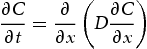
During the treatment, active atoms contained in VGE will be diffused to the surface and interior of titanium alloy under the action of strong electric field and concentration gradient. Previous studies have shown that the diffusion mechanism of carbon and nitrogen in titanium alloy is interstitial diffusion mechanism [18]. The concentration of particles in the process of strengthening changes with the diffusion depth and processing time, which can be described by
Arc discharge produces a large amount of active particles during strengthening process. The concentration gradient between surface and matrix is formed after the increase in active atoms adsorbed on the surface, which is conducive to the diffusion.
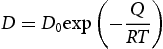
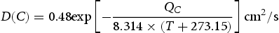
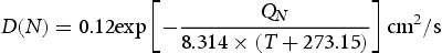
The diffusion coefficient of carbon and nitrogen in titanium alloy can be obtained by Equation (4). The frequency factor (D0) of carbon in the diffusion system is 0.48, so the diffusion coefficient of carbon can be given by
Catalytic accelerated kinetic model
Rare earth (RE) elements exhibit good chemical activity due to their 4f electronic layer structure and small electronegativity [23]. The chemical bonds in carbon and nitrogen compounds are more easily destroyed after the addition of RE, which contributes to form more active centres on the workpiece surface [24].
Since the atomic radius of RE is larger, the lattice of the workpiece is distorted, and the density of lattice defects inside the crystal increases. The lattice defects reduce the height that atomic diffusion needs to jump, which in turn changes the activation energy and diffusion coefficient of particles [25]. Consequently, the effect of RE elements on activation energy can be equivalent to that on diffusion coefficient. According to Equation (4), we know that the relationship between RE content and atomic diffusion coefficient satisfies exponential function. Taking RE content as variable, the diffusion coefficient can be obtained with the following equation:

The catalytic accelerated kinetic model can be obtained by deriving both sides of Equation (7):
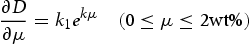
It can be seen from Equations (7) and (8) that the diffusion coefficient of carbon and nitrogen increases with increasing RE content at a certain temperature and time. Under the condition that the parameter (DI) is known, the atomic diffusion coefficient in the RE carbonitriding process can be quantitatively predicted.
Material and experimental procedures
Material
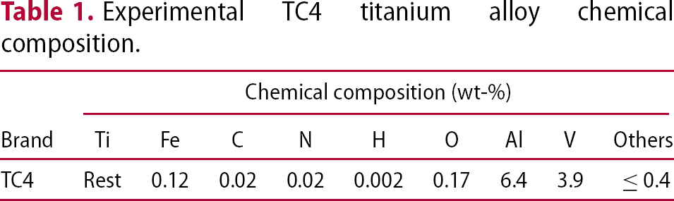
Experimental TC4 titanium alloy chemical composition.
Electrolyte compositions for carbonitriding process.
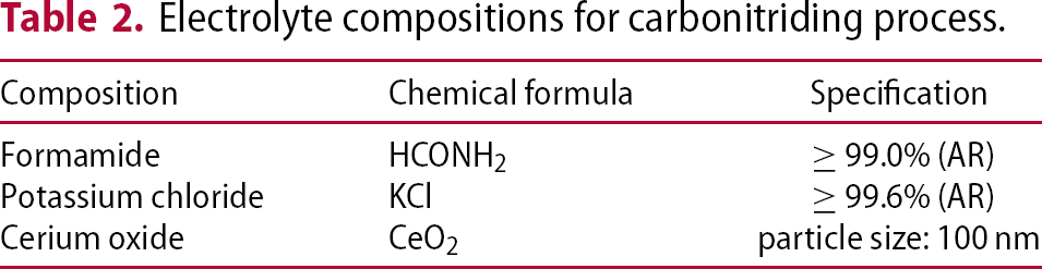
The electrolyte system [26] used in the experiment consisted of 90% formamide (HCONH2), 10% potassium chloride (KCl) and cerium oxide (CeO2). The CeO2 particles with a diameter of 100 nm were suspended in electrolyte by ultrasonic dispersion. In the carbonitriding process, HCONH2 is served as a source of active atoms, and CeO2 is served as the catalyst.
Experimental procedures
In order to obtain the coating with a certain thickness and good performance, a reasonable experimental procedure is required. Figure 1 shows the experimental process.
Experimental flow chart.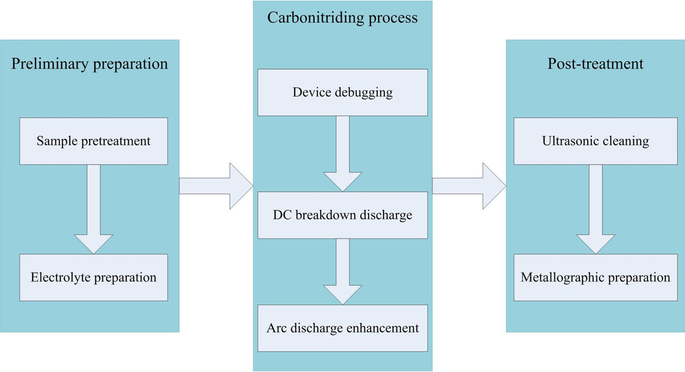
Before the experiment, the samples were ground using 400, 800, and 1200 grit sandpaper, respectively. To remove impurities and oil from the surface of the sample after grinding, it was washed with deionised water, absolute ethanol and acetone [27]. The specimens of TC4 titanium alloy were subjected to the treatment at a voltage of 320 V for 10 min. The effects of different RE (CeO2) contents (0, 1, 2 and 3 g L−1) on the strengthening result were investigated by using the univariate analysis method. Slowly increasing the DC voltage, and after the stable breakdown discharge is reached, press the pulse button to perform the carbonitriding treatment. After the experiment, the samples were cleaned using acetone and deionised water. The surface morphology and microstructure of the carbonitriding layer were examined by JSM-6360LV scanning electron microscope (SEM), and the elements distribution in the surface and cross section were measured using energy dispersive spectrometer (EDS).
Results and discussion
Comparison between the model and the experimental results
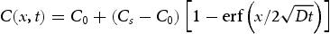
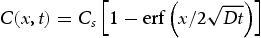
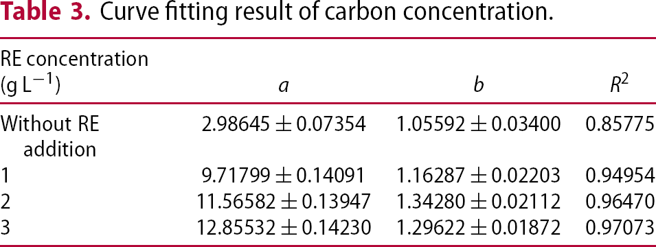
EDS test results showed that the concentration of carbon and nitrogen in the carbonitriding layer with RE addition was significantly improved, demonstrating the catalysis of RE on the diffusion of particles [28]. Comparing the experimental data with theoretical model, the diffusion process of carbon and nitrogen was further investigated. Since the same time was used for the treatment in this experiment, only the change in atomic concentration with position (x) was considered. Simplify Equation (3) as follows:

The parameter (b) is affected by the diffusion coefficient and time, which is expressed as
Curves of carbon concentration with different RE addition.
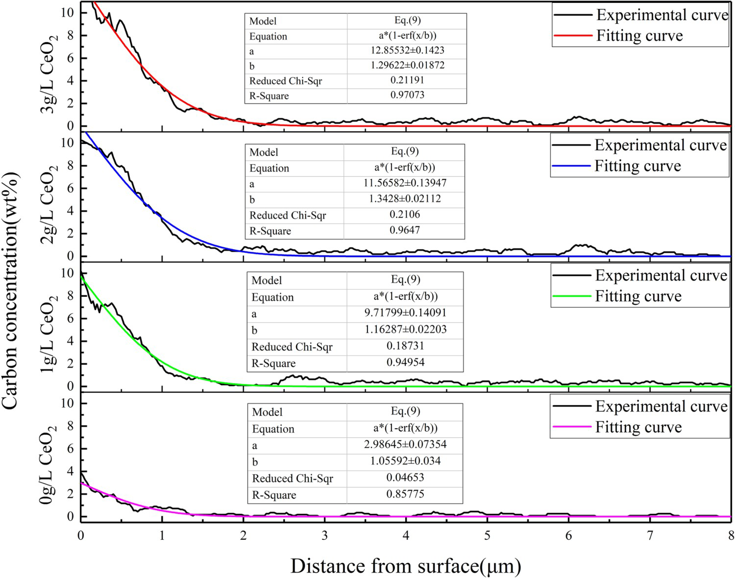
Curve fitting result of carbon concentration.
Diffusion coefficient and activation energy of carbon at different RE concentration.
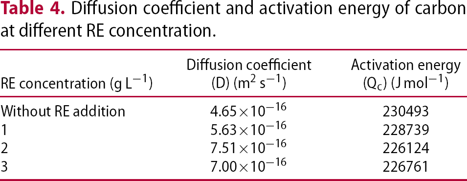
Table 4 shows that an appropriate RE concentration can effectively increase the diffusion coefficient of carbon. The activation energy of 2 g L−1 CeO2 reaches 226124 J mol−1, which is 4369 J mol−1 lower than the conventional one. With the further increase of RE, the activation energy of carbon is inversely increased by 637 J mol−1 compared to that of 2 g L−1 [30].
The atomic concentration in the carbonitriding layer is affected by depth and time, the relationship between them is given by:
Variation of carbon concentration with time and depth. (a) Without RE addition, (b) 1 g L−1, (c) 2 g L−1, (d) 3 g L−1.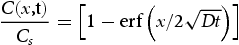
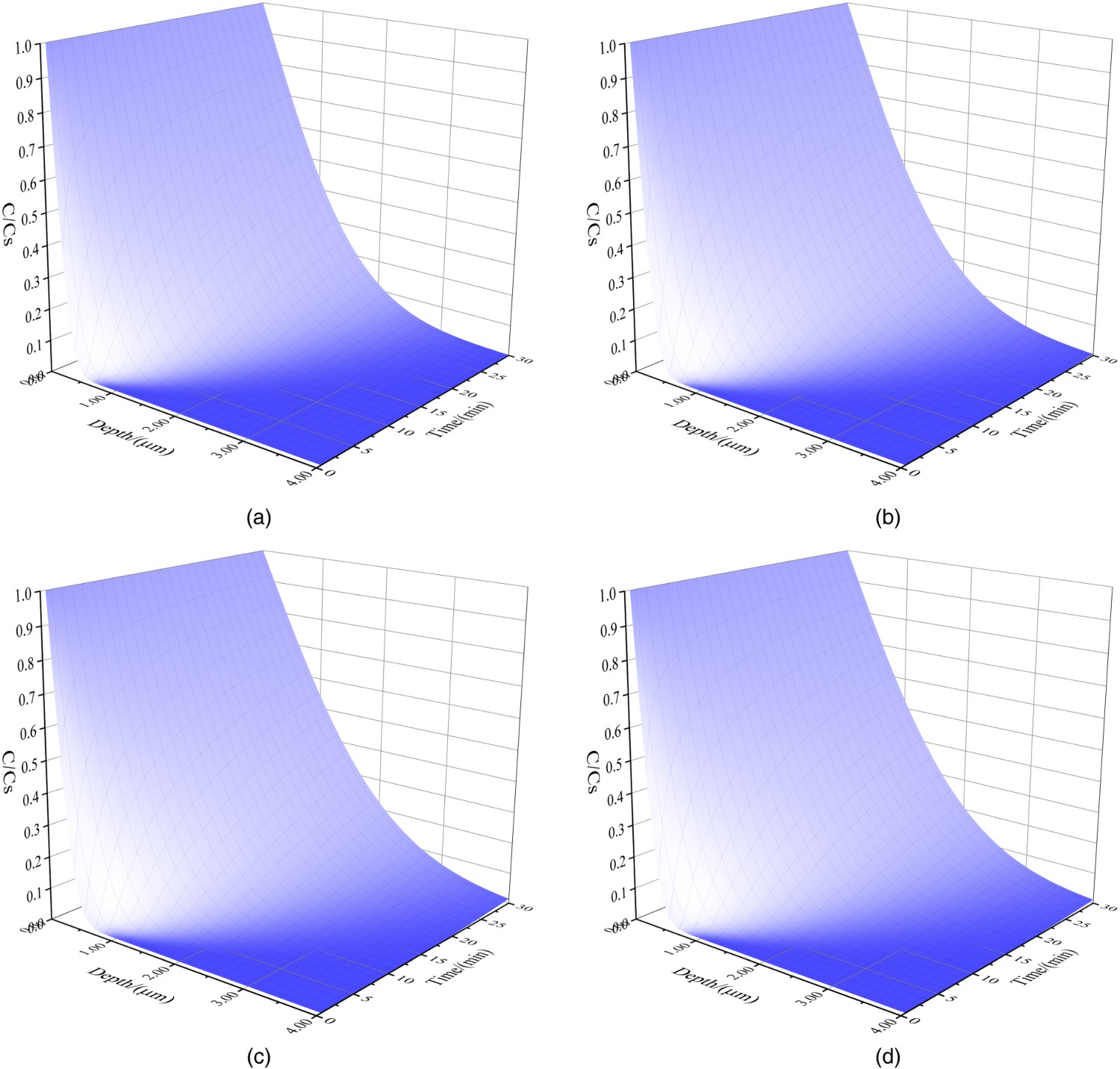
From Figure 3, the atomic content decreases in the direction of diffusion depth, and the shorter the diffusion time, the faster the decrease. After adding RE, the carbon concentration decreases slowly, and the effect is best when the content is 2 g L−1. The results showed that RE elements had a good catalytic effect on the diffusion of particles, but the effect was weakened as the increase in its concentration. The optimum content of RE was related to the electrolyte volume and workpiece size. As a result, the RE content should be controlled appropriately according to different treatment environments so as to fully exert the catalytic effect.
Figure 4 shows the comparison between the diffusion coefficient calculated by experimental results and the fitting curve expressed with Equation (7).
Experiment and fitting results of carbon diffusion coefficient under different RE concentration.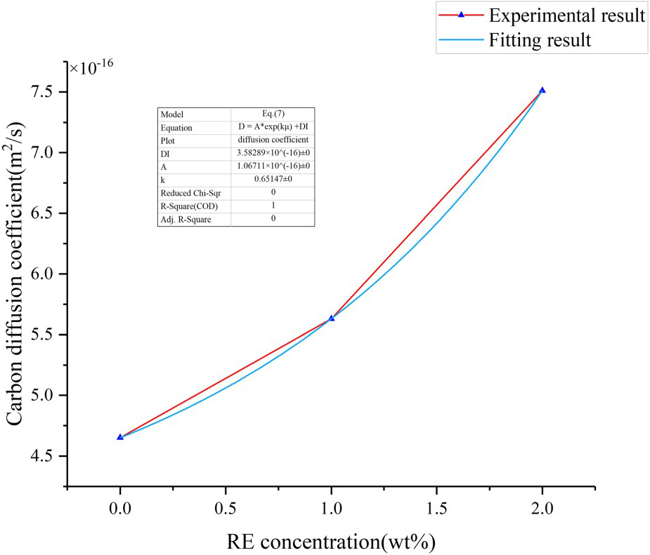
From Figure 4, we know that when the concentration of RE is in the range of 0∼2 wt-%, the Equation (7) is well matched with the experimental results, which is consistent with the theoretical analysis. The fitting result proved that the accelerated kinetic model of RE carbonitriding process was positively determined, which provided a new idea for studying the relationship between RE content and atomic diffusion coefficient in this treatment.
It can be seen from Figure 5 that the trend of nitrogen concentration is not obvious enough after RE addition. Previous studies have shown that the diffusion coefficient of nitrogen in this system is 10−14 m2 s−1, which is 100 times that of carbon, so the concentration of nitrogen varies little in the range of 0∼8 μm. On the other hand, the nitrogen concentration is so small that detection errors may be generated.
Nitrogen concentration along the diffusion depth under different RE additions.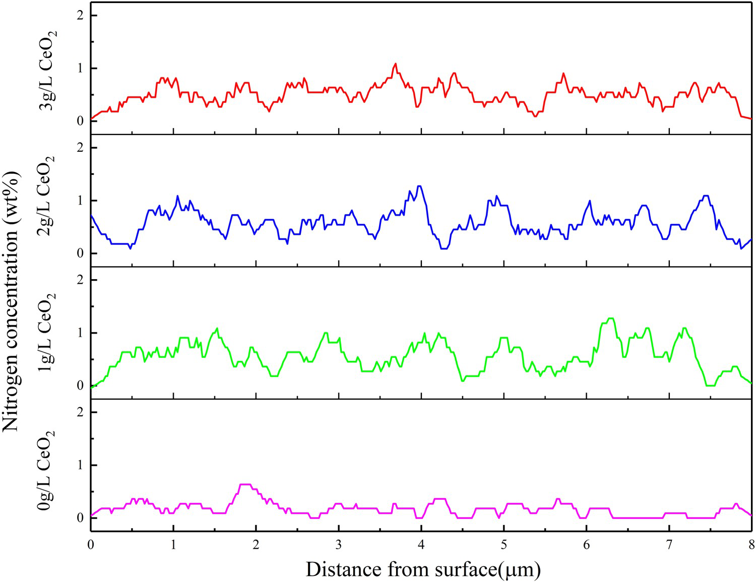
The experimental results showed that in the electrolyte system with formamide as the carbonitriding agent, plasma electrolytic strengthening process was mainly based on carburising, and the diffusion effect of nitrogen was not obvious enough. Therefore, the catalytic diffusion kinetic model in this study may not applicable to nitrogen.
Surface morphology and composition analysis
Figure 6 shows the morphology and element distribution of the workpiece surface under different RE (CeO2) concentration. It can be seen from Figure 6(a) that a small number of pores and cracks are on the surface of the workpiece, and the melt produced at high temperature is mainly distributed around them. While adding RE, the number of pores on the surface increases and the pore size is finer, just as shown in Figure 6(b). As a discharge channel, the increase in the hole is better for atomic diffusion [31]. The microcracks on the surface are highly reduced, which can improve the strengthening layer quality. When the concentration of CeO2 is higher than 2 g L−1, the growth rate of carbon and nitrogen is slowed down, and the surface smoothness is lowered, which indicates that RE should be added into the electrolyte moderately.
Surface morphology and element distribution with and without RE addition. (a) Without RE addition, (b) 1 g L−1, (c) 2 g L−1, (d) 3 g L−1.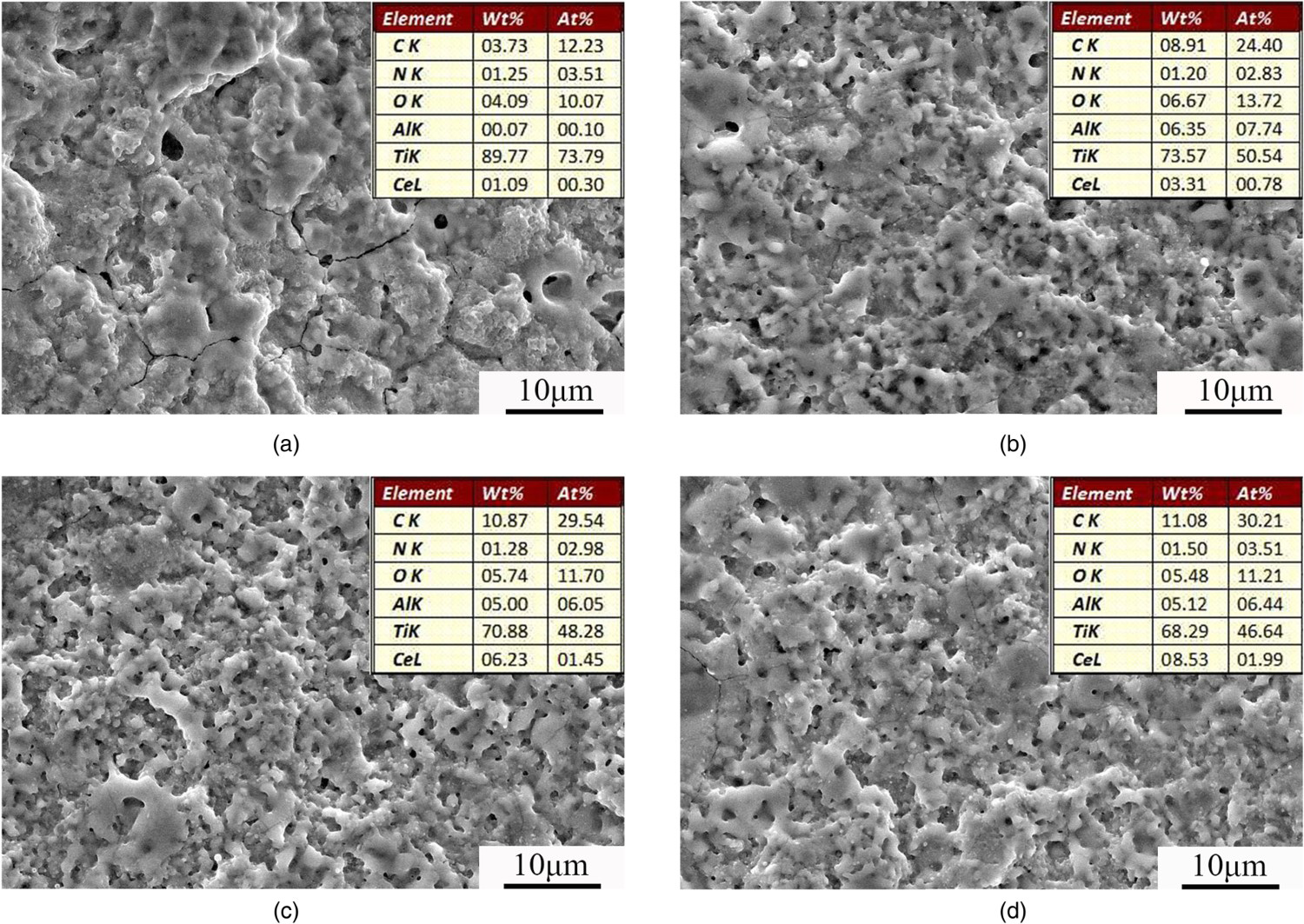
From the analysis of the elements distribution, it can be found that besides Ti and Al in TC4 matrix, the non-metallic elements (C, N, O) and the added RE element (Ce) are also included in the surface of the coating. The presence of a certain amount of oxygen (O) is due to the fact that titanium alloy is highly oxidisable in air as an active metal. As can be seen from Figure 6(a) that the mass fraction of Ce is about 1%, without RE (CeO2) addition, which possibly due to the errors caused by instrument and environmental factors. The carbon concentration on the surface of the carbonitriding layer in the range of suitable RE addition can reach 8.91 wt-%, which is about 2.5 times that of conventional treatment. However, the effect of RE elements on the nitrogen concentration was not obvious.
Section morphology and element distribution analysis
The cross-sectional morphology and element distribution of the strengthening layer in different concentrations of RE are shown in Figure 7. The coating can be divided into three parts along the depth direction: the white layer, the transition layer and the matrix. The carbonitriding layer mainly consists of a white layer and a transition layer.
Section morphology and element distribution of specimens with and without RE addition. (a) Without RE addition, (b) 1 g L−1, (c) 2 g L−1, (d) 3 g L−1.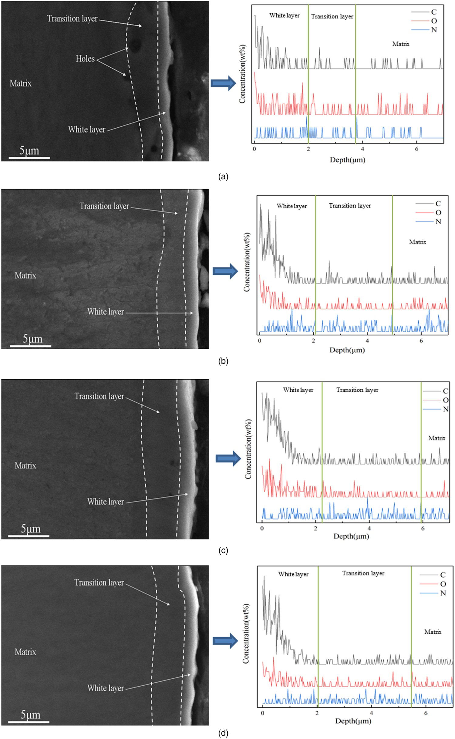
As can be seen from Figure 7(a), the white layer containing more carbon, oxygen and a small amount of nitrogen has a thickness of about 2 μm. As the increase in RE content, the carbon concentration increases rapidly but the oxygen decreases. Excluding the effects of oxidation, we can determine that the increase in carbon content makes the white layer brighter, so the white layer is also called the high carbon layer. The carbon content in the transition layer is significantly reduced, while the nitrogen is relatively high. Carbon and nitrogen with certain concentration were detected in the matrix, which indicated that a small amount of carbon and nitrogen can reach the inside of the matrix passing through the strengthening layer.
There are holes with different diameters at the boundary between the transition layer and the matrix without RE addition, as shown in Figure 7(a). Because during the growth of the strengthening layer, the surface of the titanium alloy is continuously melted and cooled by the action of the pulse discharge, and some of the pores are melted again before being completely covered by the melt. This process is similar to the formation of a micro-arc oxide film and eventually a loose porous structure will be generated at the boundary [32]. The uniformity of the coating produced without the addition of RE is poor and the thickness is only about 3.8 μm. As can be seen from Figure 7(b), the thickness of the carbonitrided layer is about 5 μm after adding RE elements. The hole disappears at the interface between the coating and the matrix, and the uniformity of the coating distribution is improved. When the content of RE is 2 g L−1, the thickness of the coating is about 6μm, which is 57% higher than that without RE addition. Furthermore, the uniformity of the thickness distribution is increased. According to the analysis, adding RE elements can improve the cross-sectional morphology and the growth rate of the layer in the same treatment time (10 min).
Conclusions
Based on the analysis of theoretical models and experimental results, the following conclusions are drawn:
In this research, the carburising was the main part of the Ti–6Al–4V alloy plasma electrolysis carbonitriding, and the catalytic accelerated kinetic model of rare earth matched the experimental results. The introduction of rare earth oxide (CeO2) effectively increased and refined the discharge holes in the strengthening layer surface, and greatly increased the surface carbon content. In addition, the significant reduction of microcracks also improved the quality of the coating surface. The addition of rare earth can affect the activation energy of carbon in the titanium alloy carbonitriding process. When the concentration of rare earth oxide (CeO2) was 2 g L−1, the activation energy reached the lowest, which was 4369J mol−1 less than conventional treatment. The thickness of the coating was about 6 μm with rare earth addition, which was about 2.2 μm higher than that by the conventional treatment method. Furthermore, the growth rate and thickness distribution uniformity of the strengthening layer increased.
Footnotes
Disclosure statement
No potential conflict of interest was reported by the authors.