
Abstract
The present investigation deals with the microstructural modification following the Bi + Sr additions to the squeeze-cast AZ91 alloy and its effect on impression creep response. The Bi + Sr additions form the Al4Sr and Sr2Bi phases besides the α-Mg and β-Mg17Al12 phases, and improves creep resistance of the AZ91 alloy. The AZ91 + 1.0Bi + 0.5Sr alloy reveals the best creep resistance among the alloys. The stress exponent and the activation energy values of all the alloys are in the range of 4–7 and 100.2–112.7 kJ mol−1, respectively, depicting the pipe diffusion-controlled dislocation creep is the governing creep mechanism. The post-creep microstructural study confirms several dislocations pile-ups around the Al4Sr and Sr2Bi phases resulting in improved creep resistance of the modified AZ91 alloys.
Keywords
Introduction
Magnesium alloys are the most promising compared to the existing structural materials owing to their light weight and high specific strength. Midst the traditionally used Mg–Al-based alloys, the AZ91 alloy has been widely used in various automobile parts owing to its better room temperature mechanical properties [1]. Nevertheless, in the powertrain applications, where the temperature ranges from 423 to 573 K, the use of the AZ91 alloy is limited. This is ascribed to the softening of β-Mg17Al12 phase (M. P. 710 K) above 403 K, resulting in its poor elevated temperature properties [2,3]. To overcome it, the AZ91 alloy was modified via different alloying additions like Ca, Sb, Bi, Sr, Si and REs. These alloying elements suppress the β-Mg17Al12 phase formation by forming new thermally stable intermetallics and impede the dislocation movement, causing superior creep response at elevated temperature [4,5]. Mo et al. [6] investigated the creep behaviour of various magnesium (Mg) alloys and reported that the addition of solute elements such as Si, Sb, Bi, Ca, Sr, RE and so on introduced thermally stable intermetallic compounds that reduced the content of the β-Mg17Al12 phase. They also concluded that the intermetallic phases strengthened the grain boundaries and impeded the dislocation movement during creep. The effect of Sr addition in the AZ91−0.5RE (wt-%) alloy was studied by Zhang et al. [7]. They reported that with Sr addition, the creep behaviour of the alloy substantially improved and it was the best in the AZ91−0.5RE−1.0Sr (wt-%) alloy. The improvement in creep behaviour was attributed to the presence of thermally stable Al4Sr intermetallic phase. Dargusch et al. [8] examined the creep response of the AE42 alloy with Sr addition. They reported that the Sr addition formed the Mg8Al4Sr phase that reduced the Al content in the α-Mg phase and improved the creep resistance of the AE42 alloy.
The impression creep technique provides a convenient method to calculate the creep parameters than the other conventional creep tests [9,10]. Ansary et al. [11] obtained the nearly identical values of the creep parameters using both the tensile and impression creep techniques. Kabirian and Mahmudi [3] investigated the creep properties of the AZ91 alloy using impression creep. They reported that the dislocation climb with diffusion through dislocation core governed creep mechanism under high stress; however, the dislocation climb aided by lattice diffusion was dominant at lower stress. The influence of Sn on the impression creep behaviour of the AZ91 alloy was studied by Mahmudi and Moeendarbari [12], and they testified that the creep properties improved owing to the formation of Mg2Sn phase. The creep behaviour of the Mg-5Sn alloy with Bi addition was investigated by Keyvani et al. [13] in impression creep. An improved creep behaviour contributed by the thermally stable Mg3Bi2 phase was reported.
Among the different casting processes developed to date, the squeeze casting is regarded as one of the best methods to obtain fine grain and defect-free structure [14,15]. Masoumi and Hu [16] studied the microstructural modification under different applied pressure and its effect on the mechanical behaviour of Mg–Al–Ca alloy. An improved mechanical response with applied pressure was reported by them. Goh et al. [17] investigated the effect of squeeze casting parameters on the mechanical behaviour of the AZ91−2.0Ca alloy, and obtained the good combination of tensile properties and hardness at squeeze pressure, melting temperature and mould temperature of 111 MPa, 1073 K and 473 K, respectively. Zhu et al. [18] compared the creep behaviour of the MRI153 alloy developed with different casting techniques. They concluded the best creep resistance in the squeeze-cast alloy.
The creep behaviour of the AZ91 alloy with Bi + Sr additions fabricated by squeeze-cast has not been studied so far. Hence, the present investigation is primarily focused on the microstructural modification due to the Bi + Sr additions to the AZ91 alloy and its effect on impression creep response.
Experimental procedure
Materials and processing
The AZ91 and its modified alloys were fabricated by employing a squeeze-casting set-up. In the squeeze-casting process, the melting was done in a mild steel crucible, and it was heated to 1023 K. The AZ91 alloy ingots, pure Mg, Al+10Sr master alloys and Zn flakes were kept inside the crucible and allowed for complete melting at 1023 K. After complete melting, the calculated amount of the preheated Bi was added into the melt. Then the melt was stirred up to 5 min to achieve the homogeneous mixture of the alloying elements in the alloys. Before pouring into the mould, the melt was held at 1023 K for 2 min for settling down the inclusions. After that, the mould was filled with molten metal, and it was subsequently pressed (200 MPa) using hydraulic arrangement until solidification took place. The sulphur hexafluoride gas mixed with argon gas was used to avoid the oxidation of the melt. The cast ingot was having a diameter of 50 mm and a height of 200 mm. The nominal composition (and the corresponding composition analysed using ICP-AES) of the alloys are AZ91+0.5Bi+0.25Sr (AZ91+0.48Bi+0.27Sr), AZ91+0.5Bi+0.5Sr (AZ91+0.45Bi+0.52Sr) and AZ91+1.0Bi+0.5Sr (AZ91+0.81Bi+0.54Sr).
Microstructural characterisation
The X-ray diffraction (XRD) (Model: Empyrean PANalytical) (CuKα, λ = 1.5406 Å) was employed for analysing the phases present in the alloys. A detailed characterisation of the microstructure of the squeeze-cast specimens before and after the creep tests was carried out using a scanning electron microscopy (SEM) (Make: JEOL JSM 6480LV). A standard metallographic technique was employed for the SEM sample preparation. Furthermore, energy dispersive X-ray spectroscopy (EDS) (Make: OXFORD INCA X-ACT) attached with the SEM was employed to identify the existing phases in the alloys. The high-resolution transmission electron microscopy (HRTEM) (Model; JEOL JEM 2100) was used to study the dislocation arrangements in the crept specimens. The specimens for the HRTEM analysis were machined up to 70 μm followed by 3 mm disc was cut. Further thinning was done by dimple grinder and ion milling.
Characterisation of creep behaviour
The creep behaviour of the alloys was evaluated using an impression creep set-up supplied by M/S. Spranktronics, India and the detailed of the same is explained elsewhere [19]. The specimen of cross-sectional area of 20*20 mm2 with a height of 6 mm along with a flat indenter of 1.5 mm diameter was used to carry out the impression creep tests. The alloys were tested in the temperature (T) range of 423–523 K, and the stress range of 300–480 MPa corresponding to applied stress to shear modulus (σ/G) ratio of 0.020–0.032 for a dwell time up to 7200 s. After the application of load, the impression depth (h) was continuously recorded with time (t) in a computer-based data acquisition system.
Results and discussion
Analysis of the squeeze-cast microstructure of the alloys
Figure 1 displays the XRD patterns of the squeeze-cast base AZ91 and Bi + Sr added AZ91 alloys. It reveals that the primary α-Mg and β-Mg17Al12 phase peaks are the only peaks present in the base AZ91 alloy. In contrast, the AZ91 + 0.5Bi + 0.25Sr, AZ91 + 0.5Bi + 0.5Sr, and AZ91 + 1.0Bi + 0.5Sr alloys display the α-Mg, β-Mg17Al12, Al4Sr phases along with new peaks of Sr2Bi phase. The AZ91 + 1.0Bi + 0.5Sr alloy displays the highest intensity corresponding to the Sr2Bi phase, and the lowest β-Mg17Al12 phase peak was perceived in the AZ91 + 1.0Bi + 0.5Sr alloy. This confirms the reduction of β-Mg17Al12 phase with Bi and Sr alloying addition to AZ91 alloy.
XRD patterns obtained from the (a) AZ91, (b) AZ91 + 0.5Bi + 0.25Sr, (c) AZ91 + 0.5Bi + 0.5Sr, and the (d) AZ91 + 1.0Bi + 0.5Sr alloys.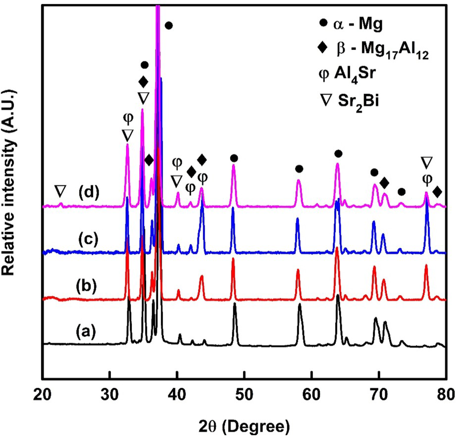
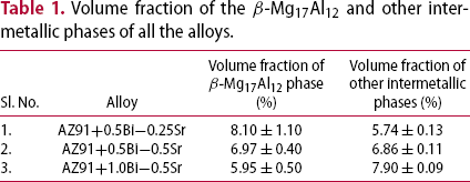
The SEM micrographs in backscattered electron (BSE) mode of the as-cast Bi + Sr comprising AZ91 alloys with corresponding EDS results are demonstrated in Figure 2(a–c). Figure 2(a) displays the SEM micrograph and EDS results of the AZ91 + 0.5Bi + 0.25Sr alloy. The EDS result of the grain boundary of the AZ91 + 0.5Bi + 0.25Sr alloy displays an overall constitution of Mg-32.37Al (at.-%) confirms the presence of the β-Mg17Al12 phase. The AZ91 + 0.5Bi + 0.5Sr alloy, as presented in Figure 2(b) displays the needle-shaped structure along the grain boundary. The EDS analysis taken from the needle-shaped structure reveals the Al/Sr ratio of 4.3, which is a little higher than the ideal Al/Sr ( = 4.0) ratio conforming the occurrence of the Al4Sr phase. Additionally, a new Bi and Sr rich phase was also detected in the Bi + Sr added alloys. The EDS analysis performed from the AZ91 + 1.0Bi + 0.5Sr alloy (Figure 2(c)) revealed an overall constitution of Mg–12.14Sr–7.30Bi–5.47Al (at.-%) and identified as the Sr2Bi phase. Thus, the α-Mg, β-Mg17Al12, Al4Sr and Sr2Bi phases were the main constituents in all the modified AZ91 alloys. The additions of Bi and Sr in the AZ91 alloy resulted in the formation of Sr2Bi and Al4Sr phases, respectively. According to the Hume-Rothery rules, for complete solubility of two dissimilar metal atoms, their atomic size difference should be less than 15%, electronegativity difference should be very less, and the valences as well as the crystal structures of them should be the same. However, in the present investigation, both Sr and Bi are insoluble in Mg and Al. The atomic size difference between Mg–Bi, Mg–Sr, Al–Sr and Sr–Bi is 7.0%, 33.3%, 60.0% and 25.0%, respectively. The high atomic size difference between the Mg–Sr, Al–Sr, and Sr–Bi limits the complete solubility in Mg and Al. The electronegativity difference between the Mg–Al, Mg–Bi, Al–Sr, Mg–Sr, and Sr–Bi are 0.3, 0.7, 0.7, 0.4, and 1.1, respectively. From the electronegativity difference, it is evident that the Mg–Bi, Al–Sr, and Sr–Bi systems tend to form intermetallic compounds than solid solutions. In addition, the significant differences in the crystal structures as well as valencies among Mg, Al, Sr, and Bi atoms further limit their solid solubility. Therefore, owing to the limited solid solubilities of Bi and Sr in Mg and Al, they tend to form intermetallic compounds such as Sr2Bi and Al4Sr phases rather than solid solution. The similar explanation for the formation of intermetallic phases due to electronegativity difference was illustrated by Bankoti et al. [20] and Liu et al. [21]. Table 1 illustrates the volume fraction of the β-Mg17Al12 phase along with the fraction of other intermetallic phases for all the modified AZ91 alloys. It is observed that with an increase in Bi + Sr additions, the amount of β-Mg17Al12 phase formation was supressed. This is ascribed to the formation of a higher amount of other thermally stable Al4Sr, and Sr2Bi phases. The Sr addition consumed a part of the Al to form Al4Sr, leaving less amount of Al available for the formation of the weak β-Mg17Al12 phase. This would certainly increase the creep resistance of the material. Further, it is already reported that the individual addition of Bi to the AZ91 alloy resulted in the reduced volume fraction of the β-Mg17Al12 phase [22]. The combined addition of Bi and Sr to the AZ91 alloy resulted in the formation of Sr2Bi along with the Al4Sr phases. With an increase in the Bi content, the amount of Sr2Bi phase increased. The increased amount of Sr2Bi phase along with the Al4Sr phase suppressed the formation of β-Mg17Al12 phase during solidification. Subsequently, the amount of β-Mg17Al12 phase was reduced considerably in the AZ91+1.0Bi+0.5Sr alloy compared to the low Bi-containing AZ91 + Sr alloys i.e. AZ91+0.5Bi+0.25Sr and AZ91+0.5Bi+0.5Sr alloys, as observed in Table 1. The maximum volume fraction of Sr2Bi and Al4Sr phases were identified in the AZ91 + 1.0Bi + 0.5Sr alloy, and the lowest volume fraction was obtained in the AZ91 + 0.5Bi + 0.25Sr alloy. Furthermore, the highest β-Mg17Al12 phase volume fraction was perceived from the AZ91 + 0.5Bi + 0.25Sr alloy, and the lowest volume fraction was obtained in the AZ91 + 1.0Bi + 0.5Sr alloy.
Typical SEM micrographs in backscattered electron (BSE) mode of the squeeze-cast (a) AZ91 + 0.5Bi + 0.25Sr, (b) AZ91 + 0.5Bi + 0.5Sr and (c) AZ91 + 1.0Bi + 0.5Sr alloys with EDS results showing the presence of β-Mg17Al12, Al4Sr, and Sr2Bi phases. Volume fraction of the β-Mg17Al12 and other intermetallic phases of all the alloys.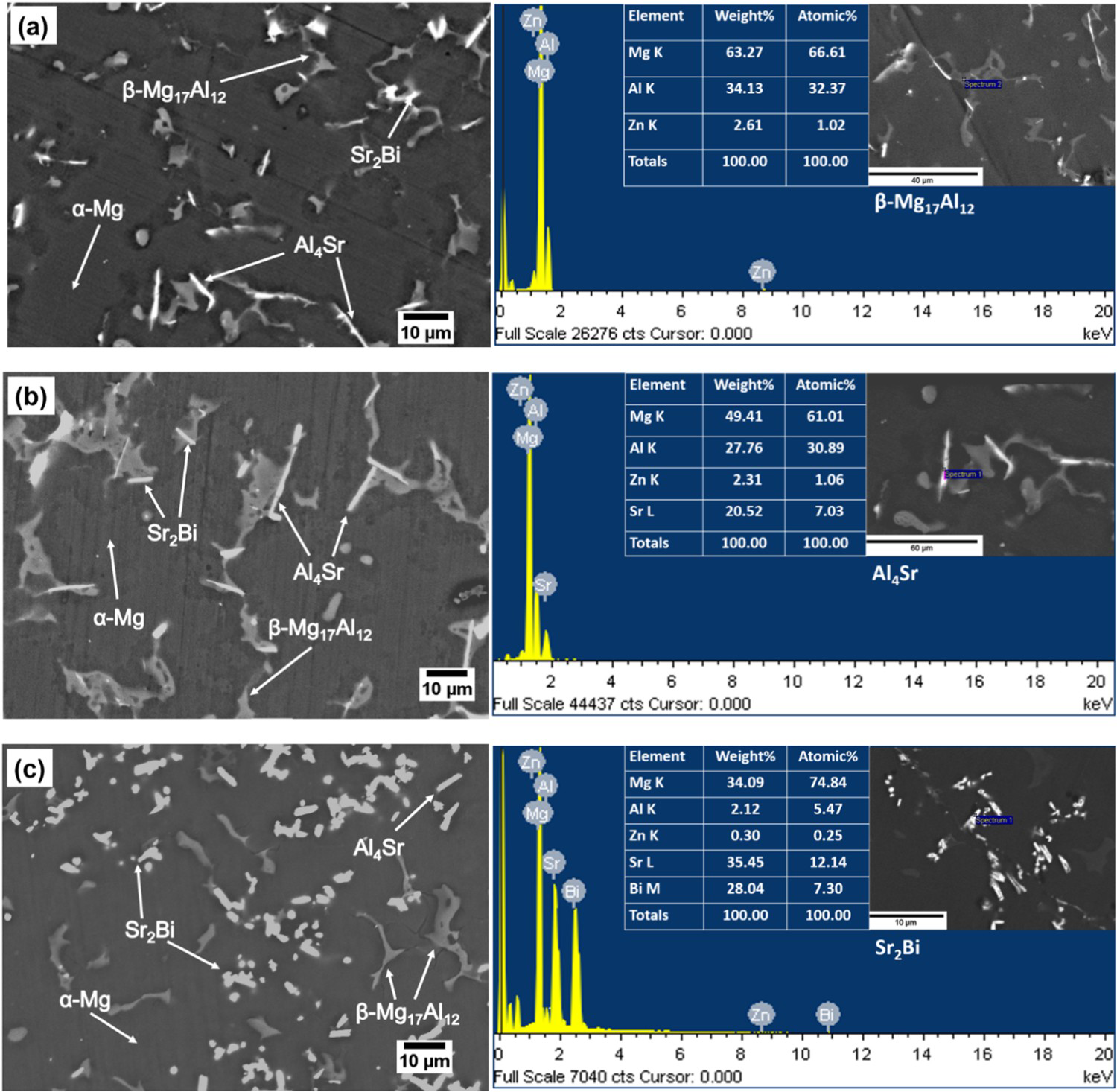
Impression creep behaviour
Figure 3(a) demonstrates the variation of impression depth (h) as a function of time (s) for all the alloys creep tested at T = 473 K and normalised stress of σimp/G = 0.029. The shear modulus (G) is a function of temperature and it is calculated from the relation G (MPa) = 18460−8.2 T (K) [23]. A transient (primary) creep regime with a well-defined secondary creep (steady-state) regime for all the alloys are obtained. There is a linear increase in impression depth with time in the second stage. The tertiary creep regime was not recorded in the impression creep test as the mode of loading in impression creep was compression. The variation of impression velocity (dh/dt) with time (s) corresponding to impression depth vs. time is plotted for all the alloys, as shown in Figure 3(b). A sharp decline in impression velocity is noticed in the transient creep regime, and the impression velocity achieved steady-state in the secondary creep region. The work hardening phenomena play a dominant role in the primary creep stage and reduce the creep rate of the specimens. However, at the secondary creep stage, work hardening and recovery processes are in equilibrium to acquire the steady state.
Typical impression creep curves displaying the (a) impression depth vs. time as well as (b) impression velocity vs. time for all the alloys.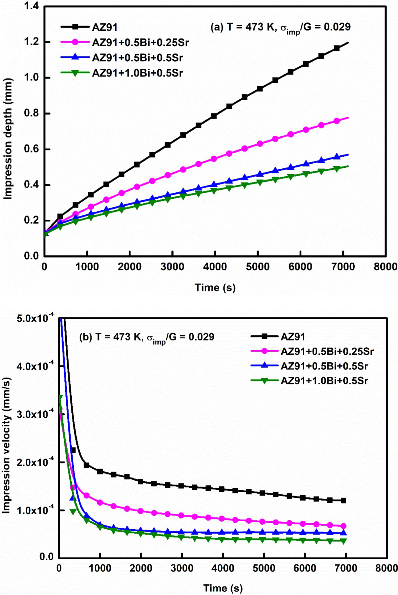
The creep resistance of all the alloys are compared by plotting their minimum impression velocity values at a temperature of 423 and 498 K with varying stress range from 300 to 480 MPa in the three-dimensional plots as presented in Figure 4(a,b). It is observed that the AZ91 alloy with Bi + Sr addition exhibited the lower creep rate than the base AZ91 alloy. Furthermore, at a higher temperature, the difference in impression velocity is more significant, indicating that the Bi + Sr added alloys are superior for creep resistance.
Three-dimensional representations exhibiting the combined effect of temperature and stress on the impression velocities of all the alloys at (a) 423 K, and (b) 498 K.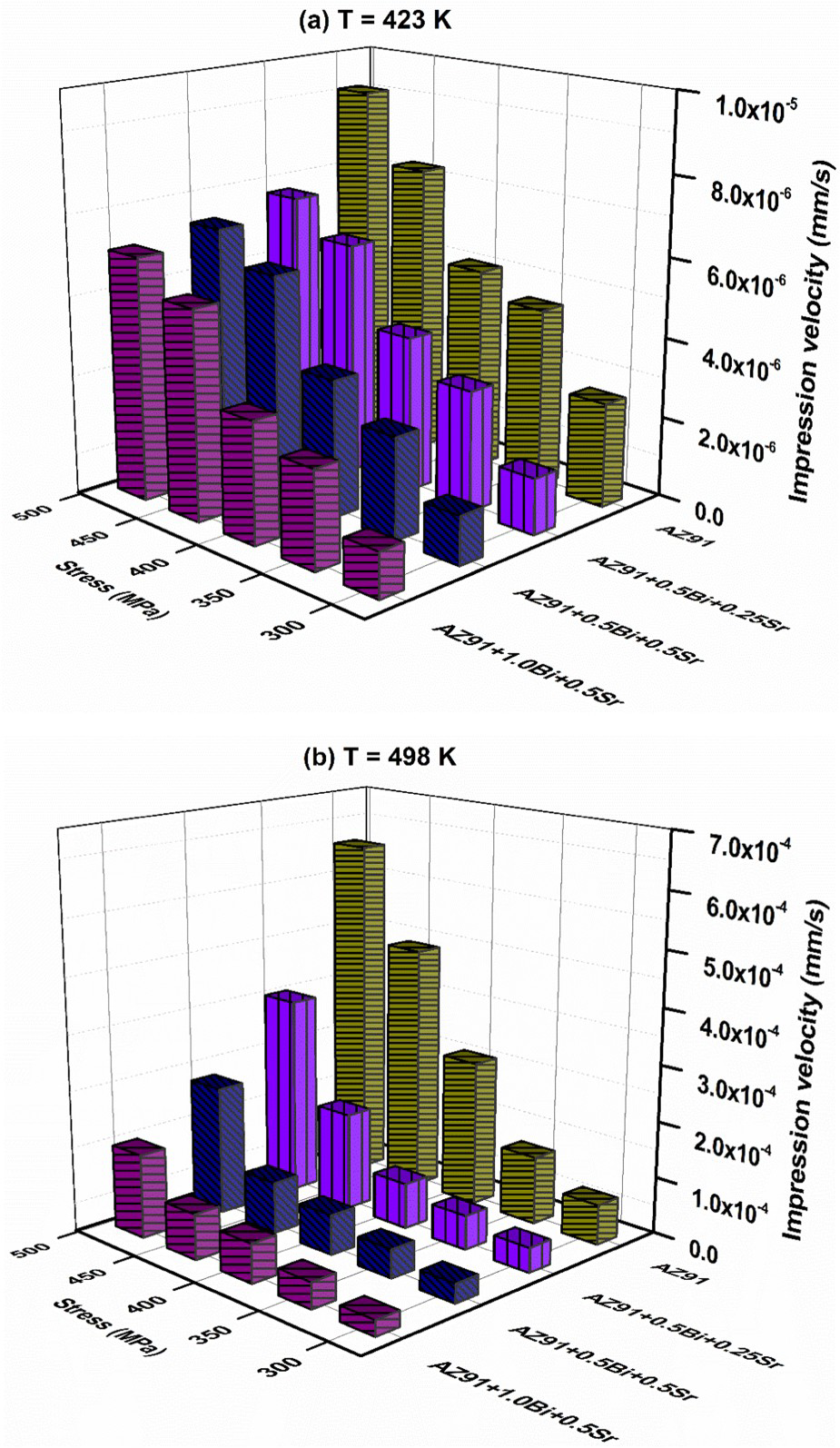
The creep resistance of the AZ91 alloy is attributed to the presence of the β-Mg17Al12 phase precipitate; however, at high-temperature exposure (above 403 K), the β-Mg17Al12 phase gets soften and decrease the creep resistance by promoting grain boundary sliding [24]. In addition, the morphology of the β-Mg17Al12 phase plays a significant role in improving the creep response of the AZ91 alloy. The continuous precipitation of the β-Mg17Al12 phase improves creep resistance, whereas, the discontinuous precipitation of the β-Mg17Al12 phase results in poor creep resistance [22]. Therefore, decreasing the formation of β-Mg17Al12 phase and introduction of thermally stable secondary phases is the best way to reduce the creep rate of the AZ91 alloy. The improved creep property of the Bi + Sr added AZ91 alloys is due to the existence of thermally stable Al4Sr and Sr2Bi intermetallic phase along the grain boundary. Among all the modified alloys, the AZ91 + 1.0Bi + 0.5Sr alloy showed the best resistance to creep deformation due to strengthening provided by the secondary phases with high thermal stability.
Creep mechanism analysis
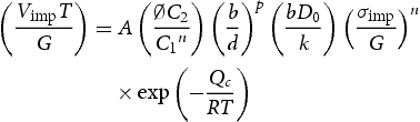
The creep mechanism is determined from the analysis of TEM micrograph as well as the calculation of stress exponent, n with activation energy, Q. The Mukherjee-Bird-Dorn equation is given by [25]
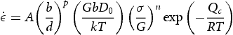
 represents the creep rate calculated from the steady-state region and σ is the stress employed, A is material constant, b denotes burgers vector, d stands for grain size, p is grain size exponent, G is the modulus in shear, D0, k, T, R are the diffusion coefficient, Boltzmann's constant, absolute temperature (K) and the universal gas constant, respectively; n and Qc are the stress exponent and the activation energy of creep.
Equation (1) can be correlated with the impression creep data. The applied stress (σ) is the impression stress (σimp), and the correlation between creep rate ( ) and impression velocity (Vimp) is as follows:
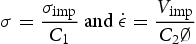
 is the punch diameter.
Furthermore,
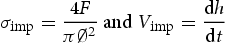
From Equations (2) and (3), Equation (1) can be rewritten as follows [12]:
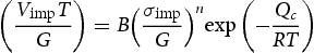

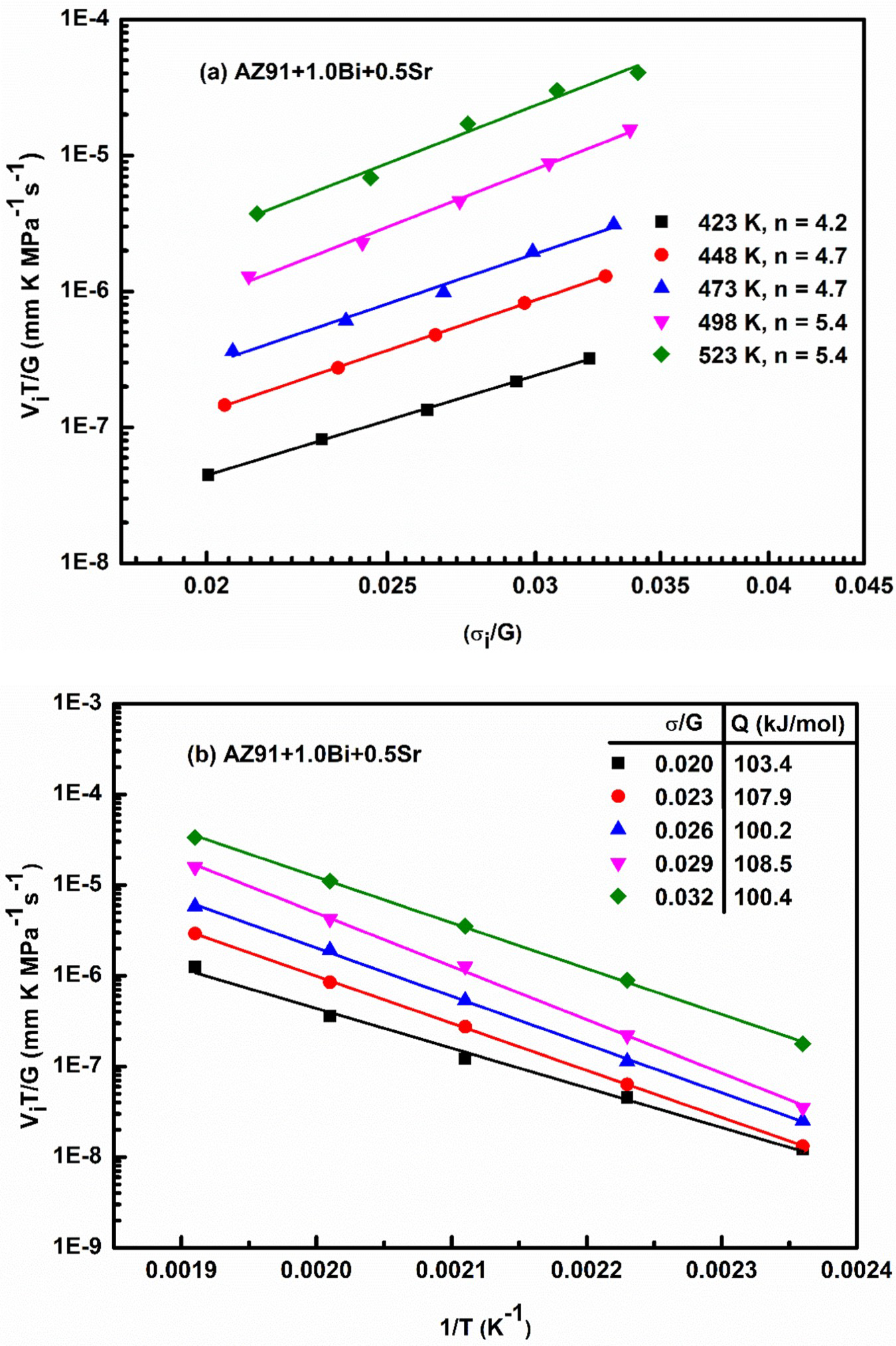
By using Equation (5), the stress exponent (n) values were obtained from a double logarithmic curve of impression velocity (temperature compensated) with stress normalised by shear modulus, i.e. The temperature-compensated normalised impression velocity as a function of (a) normalised stress, and (b) reciprocal of temperature for the AZ91 + 1.0Bi + 0.5Sr alloy. Summary of the stress exponent values (n) for all the alloys. at a constant temperature. The slope of the points fitted at constant temperature gives the n values. Similarly, the creep activation energy Q was obtained from the temperature compensated impression velocity plotted with the inverse temperature (in absolute scale), i.e.
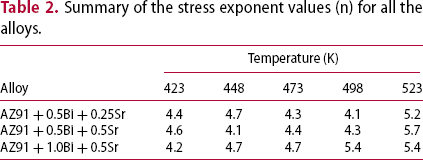
  on a semi-logarithmic scale. The n and Q values for the AZ91 + 1.0Bi + 0.5Sr alloy are displayed in Figure 5(a,b) as a representative graph for all the alloys. With varying n values, the creep mechanism also varies. The n value of 1 is for diffusion creep and 2 for the grain-boundary sliding. Further, the stress exponent varies from 3 to 7 for the dislocation creep with n = 5–7 represents the creep controlled by dislocation climb [26]. The n values are varying from 4.1 to 5.7 as shown in Table 2. Therefore, it signifies that the dislocation-climb controlled creep is the governing creep mechanism.
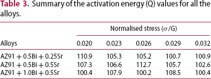
Summary of the activation energy (Q) values for all the alloys.
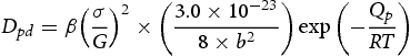
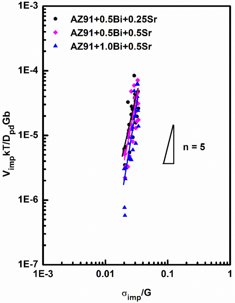
The effective diffusion coefficient is calculated by the following relation [27]:
Stress-dependence of temperature compensated impression velocity normalised by pipe diffusion coefficient (Dpd), shear modulus (G) and burgers vector (b).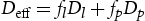

 [30], further
 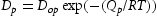 , where Dop is the pre-exponential factor and, it is calculated as
 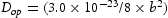 , Qp is the activation energy for pipe diffusion and b is the Burgers vector. Hence, Equation (7) can be written as below:
Microstructural investigation after creep
The microstructural characterisation beneath the indentation was carried out on the crept specimen tested at a normalised stress of σimp/G = 0.029 and temperature of 473 K. The material flow beneath the indentation was analysed by bisecting the crept specimens perpendicular to the indentation. The bisected specimens were then prepared for SEM observation following the standard metallographic technique and subsequently the SEM micrographs were obtained. A schematic of the complete procedure followed during the preparation of the specimen is shown in Figure 7(a). The material flow of the AZ91 + 0.5Bi + 0.25Sr alloy exhibiting the lowest creep resistance and the AZ91 + 1.0Bi + 0.5Sr alloy exhibiting the best creep resistance were studied and displayed in Figure 7(b,c), respectively. The micrographs display three clear, distinguishable deformation regions below the indentation and are marked as 1, 2 and 3. Region 1 is present immediately below the indentation, and no microstructural changes are observed owing to the hydrostatic nature of the stress beneath the indenter. The region 1 is also known as the dead zone and was developed without shear deformation of the alloy. In region 2, extensive plastic deformation is observed. In this region, the material flow started from the edge of the indentation owing to the deformation by shear, and it was extended towards the centre of the indentation. Few particles were elongated with the flow. Moreover, some particles were fractured due to poor resistance to the applied stress. Region 3 is present away from the indentation. A random distribution of the secondary phases is observed with no distinct flow pattern. This is attributed to the fact that the plastic deformation was confined to a localised region in impression creep. Figure 7(b) displays the flow pattern of the AZ91 + 0.5Bi + 0.25Sr alloy and the magnified image taken from region 2 clearly shows that the Al4Sr phase was aligned in the flow direction. However, some β-Mg17Al12 phase were broken into small particles signifying the instability of the β-Mg17Al12 phase at elevated temperature (above 403 K) [3]. The flow pattern of the AZ91 + 1.0Bi + 0.5Sr alloy is displayed in Figure 7(c). The AZ91 + 1.0Bi + 0.5Sr alloy shows relatively small-deformed zone than the AZ91 + 0.5Bi + 0.25Sr alloy due to the strong resistance offered by the former alloy to the applied stress at elevated temperature. The magnified image of region 2 taken from Figure 7(c) shows that few Sr2Bi phase particles were randomly distributed, and the Al4Sr and Sr2Bi phases maintained their continuity along the flow direction for their high thermal stability at the temperature.
Schematic of specimen preparation followed for creep flow analysis is shown in (a); and typical SEM micrographs in backscattered electron (BSE) mode of the as-cast specimens creep tested at T = 473 K and σimp/G = 0.029 showing material flow for the (b) AZ91 + 0.5Bi + 0.25Sr, and (c) AZ91 + 1.0Bi + 0.5Sr alloys.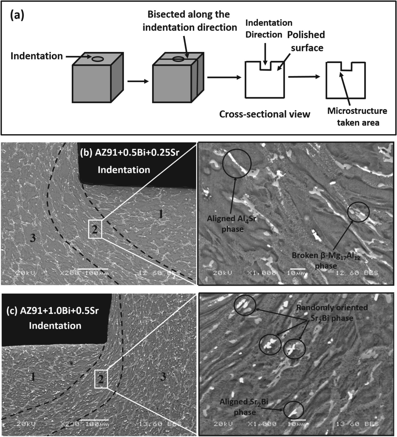
Dislocation analysis after creep
Figure 8(a–c) illustrates the typical TEM bright field images for the AZ91 + 1.0Bi + 0.5Sr alloy creep tested at T = 473 K with σimp/G = 0.029. Figure 8(a) displays the presence of several dislocations in the grain and these dislocations were hindered by the Al4Sr secondary phase and were piled-up around it. The declined creep rate obtained during primary creep stage can be ascribed to the strain hardening caused by the pile-ups and tangling of dislocation developed at grain boundaries as well as at secondary phase. The similar kind of dislocation pile-up was also observed around the Sr2Bi phase, as illustrated in Figure 8(b). Ganguly and Mondal [32] reported the similar dislocation pile-up at the periphery of Al2Ca phase. They concluded improved resistance to creep deformation was because of the pile-up as well as the tangling of dislocation at the periphery of the secondary phase. The presence of several dislocations and dislocation networks were observed in the grain interior of the α-Mg matrix as displayed in Figure 8(c). The dislocation networks presence in the grain interior is due to the interaction of the several dislocations with each other. The plastic deformation of material generally occurs owing to the movement of dislocation in the slip planes. However, the secondary phase present along grain boundaries restricts the movement of dislocation and produced dislocation pile-ups. These dislocation pile-ups generated back stress during creep and improved the creep resistance at applied stress. Wang et al. [33,34] too observed pile-up with tangles of dislocation in the AZ91 and AM50 alloys under stress. Jingli et al. [35] observed the dislocations pile-ups mostly on the basal plane. The basal planes are the main slip planes, and their critical resolved shear stress is less than the non-basal slip. Terada et al. [36] reported dislocation substructure inside primary Mg grain and dislocation glide along the basal plane under applied stress. TerBush et al. [37] studied the dislocation substructure for the AXJ530, MRI230D and MRI153M alloys and reported that the variation in creep properties was owing to the strengthening of α-Mg phase. From the dislocation analysis, it is observed that most of the dislocations were piled-up around the thermally stable Al4Sr and Sr2Bi intermetallic phases. This implies that these intermetallic phases are capable of hindering the dislocation movement under applied stress at high temperature because of their higher thermal stability. Thus, the AZ91 + 1.0Bi + 0.5Sr alloy with the maximum amount of thermally stable secondary phases provided more restriction to the dislocation movement and exhibited the best creep resistance.
TEM bright field micrographs of the AZ91 + 1.0Bi + 0.5Sr alloy following creep tested at T = 473 K and σimp/G = 0.029 showing the (a) dislocation pile-ups around the Al4Sr phase; (b) dislocation pile-ups around the Sr2Bi phase and (c) dislocations with their networks.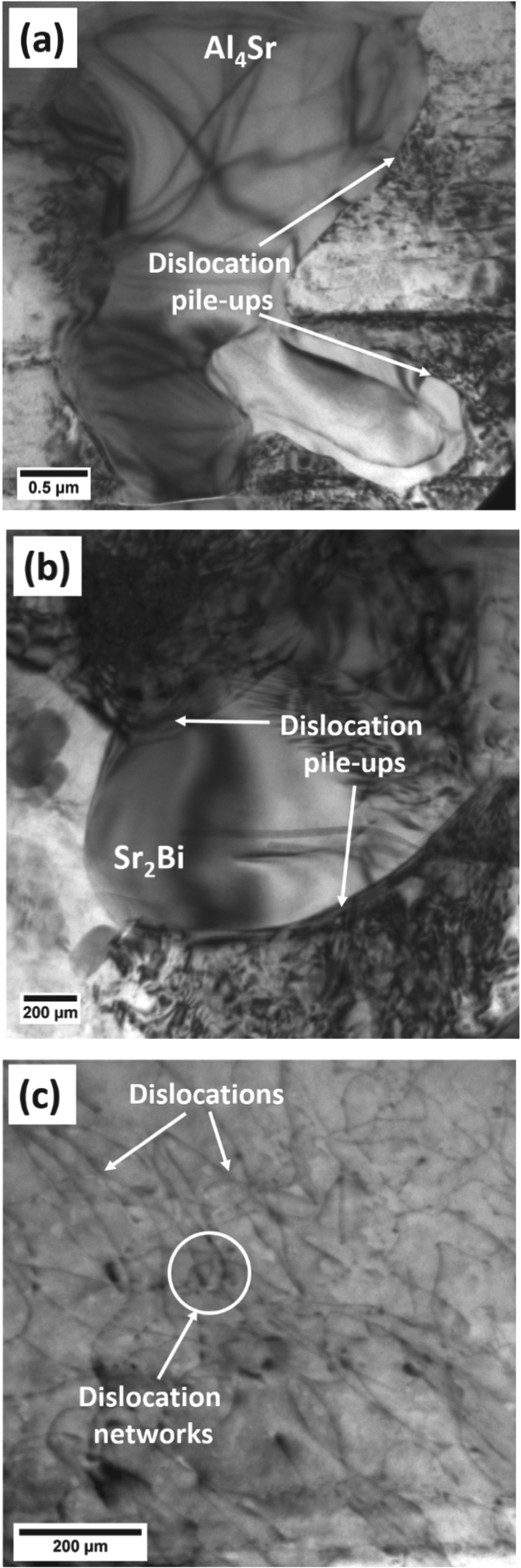
Conclusions
The microstructural modification following the Bi + Sr addition to the squeeze-cast AZ91 alloy and its effect on the impression creep response were investigated. The key conclusions drawn from the present work are listed below.
The additions of Bi + Sr formed the Al4Sr and Sr2Bi phases besides the primary α-Mg solid solution and the β-Mg17Al12 phases. In addition, the quantity of the β-Mg17Al12 phase reduced, and it was the lowest in the AZ91 + 1.0Bi + 0.5Sr alloy. The additions of Bi + Sr improved the creep resistance of the AZ91 alloy, and the AZ91 + 1.0Bi + 0.5Sr alloy revealed the best creep resistance among all the modified alloys. The stress exponent and the activation energy values were in the range of 4–7, and 100.2–112.7 kJ mol−1, respectively depicting that the pipe diffusion-controlled dislocation creep was the governing creep mechanism in the alloys in the operating stress and temperature range. The normalised creep rate with the pipe diffusion coefficient confirmed the best creep resistance of the AZ91 + 1.0Bi + 0.5Sr alloy. The post-creep microstructural study confirmed the breakage of the β-Mg17Al12 phase into fine particles, whereas the Al4Sr and Sr2Bi phases were randomly distributed and aligned in the flow direction confirming their better thermal stability. Several dislocations pile-ups observed around the Al4Sr and Sr2Bi phases resulted in the improved creep resistance of the modified AZ91 alloys.
Footnotes
Disclosure statement
No potential conflict of interest was reported by the author(s).