






Abstract
This study investigated the design and preparation of a Cr@Graphene/Fe nanocomposite inoculant via in situ synthesis in a vacuum tube furnace and mechanical grinding in a ball grinder, where material thermodynamics were considered to refine W18Cr4V high-speed steel (HSS). The effect of modification on the microstructure of W18Cr4V HSS was evaluated using high-resolution transmission electron microscopy and X-ray diffraction. The  planes of the Fe3W3C phase and
 planes of the Cr7C3 phase had collaborative points in the reciprocal space, indicating a coplanar relationship between the Fe3W3C and Cr7C3 lattices. This contributed to an improved nucleation rate and refined matrix structure. The mechanical properties of the W18Cr4V HSS, namely hardness, wear mass, and impact energy, exhibited an overall improvement after modification. Specifically, the hardness and impact toughness after modification and heat treatment increased to 65.2 HRC and 0.209 MJ m−2, respectively.
Introduction
Technological advancements in alloy design and production have led to the widespread use of W18Cr4V high-speed steels (HSSs) as mechanical engineering materials. Specifically, W18Cr4V HSS is often the most suitable tool material for blades and moulds, but traditional casting can lead to severe elemental segregation due to process limitations during solidification. This is caused by cracking and splitting of the contiguous network of high-alloy carbides enriched at the grain boundaries in the W18Cr4V matrix, thereby degrading the macro-mechanical properties of the HSS and significantly limiting its application. To overcome these issues, previous studies have investigated several methods to improve the microstructure of W18Cr4V, including metamorphic inoculation treatment, powder metallurgy, and injection moulding technology. As powder metallurgy and injection moulding technologies for HSS preparation are not yet well established, the process costs are high. Alternatively, metamorphism inoculation is a simple and low-cost method for effective refinement of the HSS microstructure for improved mechanical properties. This modification treatment involves the addition of an inoculant to the melt to refine both the matrix and eutectic carbides via inoculation and/or surface-active effects in the melt [1-8]. Previous reports have proposed a variety of compound inoculants to eliminate various defects in material structures and to improve the mechanical properties of materials. Li reported that an in situ inoculant in GCr15 bearing steel refined the grain size from 376 to 116 µm, thereby achieving a grain refinement rate of 69% [9]. Belyanchikov used Ti, Nb, V, Zr, and other elements to form nitrides with N to facilitate the precipitation of MC as the HSS melt solidified during refining [10]. Further, Khraisat et al. reported that the addition of 1–2% Ni led to improved hardenability and toughness [11].
This study investigated a Cr@Graphene/Fe nanocomposite inoculant to refine the grains and improve the mechanical properties of W18Cr4V HSS. The carbide morphology and distribution within the W18Cr4V HSS were modified by introducing the composite inoculant to the molten W18Cr4V HSS. Specifically, the dominant phase of chromium carbides was successfully converted from brittle Cr23C6 dendrites to Cr7C3 particles, which offer superior strength and hardness and are highly robust against wear and corrosion at both ambient and elevated temperatures. Furthermore, a spatial model was established by Materials Studio software and verified using high-resolution transmission electron microscopy (HRTEM) observations and analysis.
Experimental
Inoculant preparation
Cr powder (90 wt-%) and graphene powder (10 wt-%) were thoroughly mixed using a high-energy ball mill at 250 r min−1 for 8 h. The mixed powder was sintered in a vacuum tube furnace (SK-G04143) at a heating rate of 3°C min−1 to 1160°C and held at the target temperature for 0.5 h [12]. The sintered product mainly comprised chromium carbide ceramic particles. The chromium carbide ceramic particles (50 wt-%) were mixed with graphene powder (0.5 wt-%) and iron powder (49.5 wt-%) in a high-energy ball mill at 700 r min−1 for 6 h. Overall, this preparation procedure included powder metallurgy, mechanical grinding, and vacuum heating, and ensured that the Cr@Graphene/Fe nanocomposite inoculant was homogenous for enhanced wettability.
Melting and heat treatment
The chemical composition of the HSS raw material was Fe 74.78 wt-%, C 0.73 wt-%, W 18.21 wt-%, Mo 0.21 wt-%, Cr 4.2 wt-%, V 1.1 wt-%, Si 0.28 wt-%, and Mn 0.44 wt-%, with S ≤0.03 wt-% and P ≤0.02 wt-%. The HSS was melted completely in a vacuum induction furnace (ZG-0.025) under vacuum (6.67 × 10⁻³ Pa). The Cr@Graphene/Fe inoculant (0.5 wt-%) wrapped in aluminium foil was added to the molten steel, electromagnetically stirred for 1–2 min, and poured into a ϕ70 mm cast iron mould. The test HSS ingots were cooled and weighed approximately 10 kg. Two sets of HSS ingots were produced, namely HSS 0 without inoculants and HSS 1 with inoculants.
All ingots were further heat-treated using high-temperature tempering [13], which involved a series of forging, annealing, quenching, and tempering (Figure 1). The cracks and edges were ground beforehand to prevent the propagation of cracks in the HSS during forging. The initial and final forging temperatures were approximately 1160°C and 900–950°C (Figure 1(a)). The samples were preheated at 860°C for 12 min before forging. The structure of the forged samples had a high hardness and significant residual machining stress and was thus annealed immediately (Figure 1(b)). High-temperature quenching is suitable for W18Cr4V HSS, but abnormal austenite grain growth, quenching deformation, and oxidative decarburisation can occur if the temperature is too high. The optimal quenching temperature of 1260°C was determined during preliminary testing (Figure 1(c)). Triple tempering heat treatment was conducted at 560°C for 1 h each (Figure 1(d)).
Heat treatment of W18Cr4V HSS, including (a) forging, (b) isothermal spheroidizing annealing, (c) quenching, and (d) tempering.
Characterisation
The microstructures of the HSS samples and the inoculant were evaluated using scanning electron microscopy (SEM, PhilipsXL30). The inoculant was further analysed using transmission electron microscopy (TEM, JEOL 2011).
Mechanical properties
Red hardness testing was conducted using a hardness tester (HR-150A, Rockwell), where samples were heated to 600°C for 1 h. Wear testing was conducted using a wear tester (M-200), where samples (10 × 10 × 12 mm) with a dimensional tolerance around 0.1 mm were worn for 60 min at 200 N. Each sample was tested multiple times. The impact toughness of the heat-treated W18Cr4V samples (10 × 10 × 55 mm) was tested using a pendulum impact testing machine (JB-300).
Results
Elemental and structural analysis of inoculant
The in situ reaction used to prepare ceramic particles was observed using SEM, where the composite Cr and graphene powder formed after milling and the sintered composite powder are visualised in Figure 2(a,b). Further, the Cr@Graphene/Fe inoculant obtained after high-energy ball milling of the iron powder, graphene, and ceramic particle mixture is shown in Figure 2(c). The high-speed rotation and collision of steel balls caused the tearing of the bright lamellar graphene, which subsequently coated the ceramic particle phase. The elemental composition of the inoculant after high-energy ball milling was determined using energy-dispersive X-ray spectroscopy (EDS) (Figure 2(d,e)). Area 1 exhibited a Cr content of 47.24%, which was 34.04% higher than Area 2. Further, the C content of Area 1 was 51.73%, which was significantly higher than that of Area 2 (Figure 2(d)). These findings indicated that the small particles in Area 1 were a ceramic comprising graphene and chromium carbide, where the graphene coated the hard particle phase after high-energy ball milling. The atomic percentage of Fe in Area 2 was 82.86% (Figure 2(e)), indicating that these particles were part of the iron matrix. Overall, the SEM images suggested that the ceramic particles comprising chromium carbide and graphene were evenly dispersed within the iron matrix [14-17]. Graphene served as a stable carbon source and protected the hard particulate phases during HSS melting. The compound inoculant comprised an iron matrix and had a very similar density to the molten steel, which ensured that the inoculant and molten steel had good wettability and would not separate. X-ray diffraction (XRD) analysis revealed that the main components of the sintered in situ ceramic particles in the SEM images (Figure 2(b)) were Cr7C3, Cr3C2, and Cr2O3 (Figure 2(f)). Further, the main components of the inoculant after high-energy ball milling were Cr7C3, Fe3C, Fe, C0.055Fe1.945, graphene, and Cr3C2 (Figure 2(g)). The diffraction peak intensities indicated that the inoculant was dominated by the Cr7C3 phase, which can serve as a heterogeneous nucleation centre to refine the grains of W18Cr4V HHS.
SEM images of the composite Cr and graphene powder (a) after milling and (b) after sintering at 1160°C for 0.5 h. (c) SEM image of the Cr@Graphene/Fe inoculant with corresponding EDS spectra for (d) Area 1 and (e) Area 2. Corresponding XRD patterns for (f) sintered composite powder in (b) and (g) Cr@Graphene/Fe inoculant in (c).
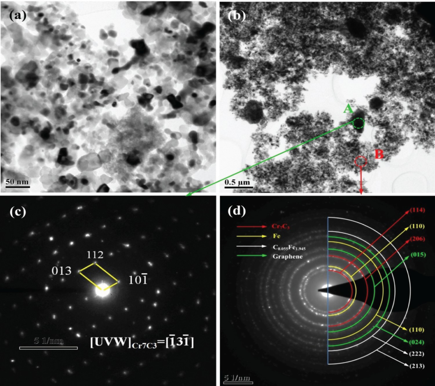
TEM analysis was conducted to evaluate the microscopic morphology and phases of the inoculants (Figure 3). The particles were primarily classified as three types, namely (1) tiny particles (10–40 nm) (Figure 3(a)); (2) larger particles (200–400 nm) (Figure 3(b)); and (3) large particles formed by the agglomeration of tiny particles. This agglomeration occurred because the nano-sized inoculant grains readily adsorbed one another and agglomerated during high-energy ball milling. The selected area electron diffraction (SAED) pattern of Region A in Figure 3(b) is shown in Figure 3(c), where the set of different diffraction spots were identified as the Cr7C3 phase based on the two diffraction spots that corresponded to crystal planes with spacings of 3.51 and 4.24 Å and an angle of 104.86°. The two planes closely match the (a,b) Low magnification TEM images of Cr@Graphene/Fe nanocomposite inoculant with corresponding SAED patterns for (c) Region A and (d) Region B in (b). and
and  planes of Cr7C3, which have an angle of 105.32°. The SAED pattern of Region B in Figure 3(b) exhibited a number of polycrystalline diffraction rings (Figure 3(d)). Further analysis revealed that the inoculant mainly consisted of Fe, Cr7C3, graphene, and C0.055Fe1.945. The ceramic nanoparticles had a high surface binding energy and were prone to heterogeneous nucleation during HSS solidification [18,19].
Effect of inoculant modification on the microstructure of as-cast W18Cr4V HSS
The metallographic photographs of the as-cast W18Cr4V were compared to demonstrate that the microstructure of the modified HSS was refined (Figure 4(a,b)). The microstructure of the as-cast HSS comprised three main classes, namely (1) black regions at the centre, (2) bright white regions at the periphery, and (3) the dark grey regions at the grain boundaries. The grain size, dendrite spacing, and carbide network thickness of the as-cast W18Cr4V were measured using Image-Pro software, using the straight-line intercept method based on a minimum of 50 measurements. The inoculant modification reduced the grain size in the as-cast W18Cr4V from 39.45 to 27.71 µm, thereby giving a grain refinement rate of 29.76%, while the dendrite spacing and network thickness decreased from 41.67 to 30.08 µm and 23.21 to 11.32 µm, respectively (Table 1). The SEM images of the as-cast W18Cr4V visualised the reduction in the amount and size of fishbone eutectic ledeburite in the grain boundaries of the as-cast modified microstructure, where ledeburite comprised a mixture of pearlite, cementite, and eutectic cementite at room temperature (Figure 4(c,d)). The fish-bone-like ledeburite was broken, and the δ eutectic carbide distribution was independent of modification. According to the Hall–Petch formula [20], the modified W18Cr4V HSS has a higher yield strength, which allows for high strength, hardness, good ductility, and toughness [21]. The SEM microstructural analysis of the as-cast HSS (Figure 4(e)) was complemented by EDS analysis to investigate the elemental composition of the carbides in two areas, namely Area 1 and Area 2 (Figure 4(f,g)). The atomic percentages of C, Cr, Fe, W, and V in Area 1 were 41.72%, 4.82%, 27.18%, 23.31%, and 2.97%, respectively (Figure 4(g)). Area 2 had a 15.23% higher CR content than Area 1, but had a lower C content of only 29.57% (Figure 4(f)). The fishbone carbides in the HSS had a higher Cr content and lower C content than the granular carbides. The graphene-coated ceramic particles served as a heterogeneous nucleation core for carbides in the modified HSS steel, while the graphene in the inoculant also formed a carbon-rich micro-area near the ceramic particles. This facilitated the formation of Cr7C3 from the Cr in the HSS and the C in the micro-area. As Cr23C6 carbide is a high-Cr low-C carbide, the Cr23C6 carbides were more likely to precipitate near the fish-bone eutectic carbides. According to the EDS atomic percentage analysis, the fish-bone carbides in Area 2 consisted mainly of M6C type carbide (Fe3W3C) and M23C6 type carbide (Cr23C6). The EDS spectrum of the granular carbides in Area 1 revealed a carbon-rich micro-area with an atomic percentage of C of 41.72. Thus, the particles in Area 1 were mainly MC- and M7C3-type carbides. Granular Cr7C3 offers better mechanical properties than dendritic Cr23C6 carbides, and optical metallographic images of the as-cast HSS (Figure 4(a–d)) revealed that the modified HSS had a significantly lower proportion of HSS network carbides. This also indicated that the content of Cr23C6 carbides had decreased.
Optical metallographic photograph of the as-cast (a) unmodified and (b) modified HSS. SEM images of the as-cast (c) unmodified and modified HSS. (e) SEM image of the as-cast HSS with corresponding EDS spectra for (f) Area 2 and (g) Area 1. Comparison of the as-cast W18Cr4V microstructures.

Effect of inoculant modification on the microstructure of heat-treated W18Cr4V HSS
The microstructure of the modified W18Cr4V HSS was significantly improved after tempering. The SEM images of the triple tempered (560°C) modified and unmodified W18Cr4V HSS illustrated that the secondary carbides in the modified HSS contained a larger number of finer grains that were more evenly distributed in the matrix (Figure 5(a,b)). During heating and tempering, the average atomic kinetic energy increased, causing alloying atoms to precipitate from the matrix and form secondary carbides with elemental carbon. This led to the transformation of residual austenite to secondary martensite. The SEM images of the modified W18Cr4V revealed fine particle phases distributed within the iron phase. The EDS analysis of Area A in the SEM images (Figure 5(c)) indicated that the mass percentages of C and W were 6.82 and 54.81 wt-%, respectively. However, the mass percentage of W element at Area B (Figure 5(e)) dropped by 43.19 wt-% to 11.62 wt-% (Figure 5(f)). This indicated that the particle phase in the steel matrix was predominantly tungsten carbide with a smaller amount of chromium carbide.
SEM images of the triple tempered (560°C) (a) unmodified and (b) modified HSS. (c) SEM image of the tempered modified HSS with (d) corresponding EDS spectra of Area A. (e) SEM image of the tempered modified HSS with (f) corresponding EDS spectra of Area B. XRD patterns of the triple tempered (560°C) (g) unmodified and (h) modified HSS.
The XRD patterns confirmed that the microstructure of the unmodified control HSS contained ferrite, CFe15.1, C0.055Fe1.945, Fe4V, Cr23C6, and Fe3W3C phases after tempering (Figure 5(g)), while the diffraction peaks attributed to the Cr23C6 and CFe15.1 phases disappeared and the Cr7C3 phase appeared in modified HSS (Figure 5(h)). The reference powder diffraction file (PDF) cards (# 52–0512) of the CFe15.1 phase stated that the crystal structure was a face-centred cubic structure. The XRD pattern of the retained austenite in the unmodified HSS (Figure 5(g)) indicated that inoculation of the modified W18Cr4V HSS led to a change in the type of chromium carbide and increased transformation of the retained austenite to martensite. The absence of the diffraction peak attributed Cr23C6 carbide indicated that the content of Cr23C6 was very low, while the content of the Cr7C3 phase in the modified HSS had increased (Figure 5(h)).
Effect of inoculant modification on the mechanical properties of W18Cr4V HSS
The mean measured hardness and red hardness values of the modified W18Cr4V HSS were superior to the unmodified samples (Figure 6(a)). Specifically, the hardness improved from 62.9 HRC in the unmodified HSS to 65.2 HRC when inoculated, while the red hardness improved by 1.7 HRC higher to give 62.5 HRC for the modified HSS. These improved mechanical properties were attributed to the higher carbide content and refined carbide particles in the modified W18Cr4V HSS due to the ceramic particles in the Cr@Graphene/Fe inoculant, thereby giving higher hardness and better stability. Moreover, maximum integration of carbon and alloy elements into the austenite was achieved during the quenching process, which eventually led to the precipitation of carbides after tempering for a secondary hardening effect.
(a) Hardness and red hardness of the unmodified and modified HSS. (b) Wear mass of the unmodified and modified HSS. Wear surface of the (c) unmodified and (d) modified HSS. Deep field 3D of the (e) unmodified and (f) modified HSS.
The average wear mass of the modified W18Cr4V HSS was considerably lower than that of the unmodified HSS (Figure 6(b)). Specifically, the 9.4 mg wear mass of the unmodified W18Cr4V decreased by 5.5 to 3.9 mg in the modified samples. Microscopic analysis of the unmodified and modified W18Cr4V samples after wear testing revealed deeper parallel groove marks across the entire surface of the unmodified samples, as well as more black areas (Figure 6(c)). In contrast, the worn surface of the modified specimen exhibited relatively shallow and dense groove marks with significantly fewer black areas (Figure 6(d)). The microscopic three-dimensional (3D) wear structure of the HSS (Figures 6(e,f)) was characterised as a significantly reduced average groove depth of 32.81 µm in the modified W18Cr4V HSS, which was indicative of superior wear resistance. This improvement was attributed to the more uniform dispersion of secondary carbide particles and the denser matrix of the modified HSS, which slowed debris formation during wear.
The impact toughness of the heat-treated W18Cr4V samples (Figure 7(a)) was measured and evaluated based on macro-photographs of the unmodified and modified impact specimens (Figure 7(b,c)). The unmodified impact specimens exhibited deeper and smoother notches. A small pendulum (0–150 J) was used for impact testing because W18Cr4V is a brittle material. The average impact energy (Figure 7(d)) was used to calculate impact toughness (Table 2). Under fixed experimental conditions, the impact toughness of the modified HSS was 0.209 MJ m−2, which is 33.1% higher than the unmodified HSS. Cross-sectional SEM analysis of the unmodified HSS specimen revealed sparse and shallow dimples and pores (Figure 7(e)), while the modified HSS specimen exhibited denser, smaller, and deeper fracture dimples (Figure 7(f)). Higher magnification SEM images (Figure 7(g,h)) further visualised that the modified HSS had a larger number of deep dimples and micropores and contained fine secondary carbide particles. The improved impact toughness of the modified HSS was attributed to the presence of these finer particles, which hindered crack propagation and allowed for more deformation work absorption before fracturing. These results were consistent with the findings of Xu and Lee [22-24].
(a) Dimensional drawing of the impact specimens with macro-photographs of the (b) unmodified and (c) modified HSS. (d) Comparison of impact toughness of the unmodified and modified HSS. Fracture morphologies of the (e) unmodified and (f) modified HSS with higher magnification SEM images of fracture morphologies of the (g) unmodified and (h) modified HSS. Impact energy and impact toughness of W18Cr4V.

Discussion
Refinement mechanism of nanocrystalline inoculant
The nanocomposite inoculant was prepared using a method that involved ball milling of raw materials, an in situ reaction, and coating of graphene onto the inoculant. The high-speed rotation and collision of the steel balls refined the ceramic particles to nanocrystals, which became encapsulated in the shredded sheet-like graphene. This graphene encapsulation facilitated the in situ reaction with Cr in Cr23C6 to form Cr7C3 upon the addition of the Cr@Graphene/Fe inoculant to the molten HSS. The significantly reduced fraction of Cr23C6 led to no diffraction peaks attributed to Cr23C6 carbide in the XRD pattern of the modified HSS (Figure 5(h)). The nano-sized particles in the inoculant effectively promoted non-uniform nucleation, which greatly improved the nucleation rate during the solidification of W18Cr4V, thereby refining the as-cast structure. The martensite-particle interfaces were dependent upon the austenite-particle interfaces, where the particle phase was able to refine the austenite [25-28]. Martensite growth is affected by grain boundaries and particle phases and is hindered by nucleation cores, which leads to the formation of cryptocrystalline martensite [29]. The amount of secondary carbides in the modified HSS increased and became more uniform, while less austenite was retained in the matrix. The Rietveld method was used to measure the content of retained austenite in the HSS specimens. This is a full-spectrum linear fitting method with high analytical accuracy [30,31], as described by Equations (1)–(4). Equation (1) is the X-ray diffraction method used to obtain the diffraction intensity of Xi at any point on a diffraction curve:


Microstructural refinement mechanism of the inoculated HSS
Lower magnification TEM analysis of the W18Cr4V HSS modified with the Cr@Graphene/Fe inoculant was conducted in two regions, namely A and B, to analyse the ceramic particles (Figure 8(a)). The ceramic particles of the Cr@Graphene/Fe inoculant near the Fe3W3C phase grain boundaries were presumed to be the base of martensite and M6C heterogeneous nucleation, which facilitated the improved nucleation rate and refined matrix structure. An high-resolution TEM (HRTEM) image of Region A in Figure 8(a) is shown in Figure 8(b), with the corresponding reduced FFT pattern given in Figure 8(c). Analysis of the crystal planes, including the spacing and the angles between the crystal planes, confirmed that Region A was dominated by the Cr7C3 phase, which has an orthorhombic lattice according to its PDF (# 65–1347). Further calculations indicated that the Cr7C3 in the (a) TEM image of triple tempered (560°C) modified HSS with corresponding (b) HRTEM images of Region A and (c) FFT patterns and calibration for (b), (d) HRTEM images of Region B (e) FFT patterns and calibration of (d), (f) FFT patterns and calibration of Area I in (d), and (g) FFT patterns and calibration of Area II in (d). (h) HRTEM images of the modified HSS with corresponding (i) inverse FFT patterns and calibration of Region C in (h). crystal band axis had very similar
  plane spacing (6.437 Å) to the reference (6.071 Å). The HRTEM image of Region B in Figure 8(a) clearly comprised two areas, namely Areas I and II (Figure 8(d)). Analysis of the corresponding FFT patterns indicated that Area I was the Fe3W3C phase (Figure 8(f)), and Area II was the Cr7C3 phase (Figure 8(g)). These findings suggested that the Fe3W3C phase was associated with the grain boundary of the Cr7C3 phase. An FFT pattern across both areas (Figure 8(e)) exhibited
  planes of the Fe3W3C phase and
  planes of Cr7C3 phase in a collaborative collinear orientation in the reciprocal space, which was indicative of a coplanar relationship between the Fe3W3C and Cr7C3 lattices. The formation temperature of Fe3W3C (1341°C) is lower than the melting point of Cr7C3 (1670°C). Fe3W3C is a typical M6C carbide, where the inoculant promoted M6C nucleation while effectively hindering dendritic growth. Specifically, a four-phase peritectic reaction occurred at 1375–1300°C, and the inoculant assisted Fe3W3C nucleation and inhibited its growth in this temperature range, thereby promoting r-austenite transformation to martensite. The inverse FFT pattern of Region C in Figure 8(h) is given in Figure 8(i), which revealed that the edge dislocations at the grain boundaries contributed most to impact toughness. There was a small number of edge dislocations at the grain boundaries of the granular phase (Figure 8(i)), which prevented slip of the crystal plane to improve the impact toughness of the W18Cr4V HSS. Martensite growth was hindered by the nucleation cores, thereby facilitating the formation of cryptocrystalline martensite. Overall, modification increased the amount and uniformity of the secondary carbides and decreased amount of retained austenite in the matrix.

Crystallographic analysis of inoculation
The refinement mechanism at the macroscale is illustrated in Figure 9(a). The ceramic particles were refined to nanocrystals and became coated in the shredded sheet-like graphene under the high-speed rotation and collision of the steel balls during milling. The graphene coating on the ceramic particles prevented immediate melting and decomposition in the high-temperature molten HSS, thereby ensuring the successful entry of the nanoparticles into the steel matrix. The nano-ceramic phase introduced by the inoculant served as a heterogeneous nucleation base for martensite and M6C to refine the matrix structure. Inoculant modification facilitated the breakdown of the coarse contiguous fish-bone-like carbide to smaller separate domains. Further, the eutectic carbide at the grain boundary decomposed, and the alloy elements were more evenly distributed in the matrix. The tempering heat treatment led to an increased distance between the atoms, which promoted precipitation of the alloying elements from the matrix to form secondary carbides. Secondary martensite transformation occurred in the retained austenite, where the nano-ceramic particles introduced by the inoculant contributed to M6C formation and greatly improved the secondary hardening effect of the tempered HSS structure.
Schematic diagram of the refinement mechanism of the inoculant, including (a) the macro mechanism and (b) crystallographic mechanism.
Atomic structure models were determined using the Materials Studio software to provide a deeper understanding of the refinement mechanism at the crystallographic scale [32-34]. The  planes of the Fe3W3C phase and
  planes of the Cr7C3 phase were well matched from a crystallographic perspective (Figure 9(b)). The ceramic particles (Cr7C3) in the inoculant helped to nucleate Fe3W3C and martensite phase crystals. Therefore, the
  plane of the eutectic carbide Fe3W3C that precipitated from the liquid phase tended to grow along the
  plane of the Cr7C3 phase and form a nucleation core during solidification and cooling of the HSS melt. Thus, the inoculants enabled heterogeneous nucleation to significantly increase the number of eutectic carbide nucleation cores. During tempering, the M6C carbides preferentially grew, nucleated, and finally precipitated in the form of particles.
Conclusion
The effect of the Cr@Graphene/Fe nano-powder inoculant on W18Cr4V HSS was evaluated. The main conclusions are summarised as follows:
(1) The as-prepared Cr@Graphene/Fe nano-powder inoculant produced via high-energy ball milling comprised multi-component carbide ceramic particles wrapped in graphene. The graphene coating prevented immediate melting of the ceramic particles in the high-temperature molten steel to allow for an extended nucleation time. The nano-powder inoculant was dispersed in W18Cr4V HSS, where the high surface energy and surface binding energy of the inoculant facilitated the adsorption of the alloy atoms from the molten steel. This minimised the carbide content at the grain boundaries to improve the impact toughness of the W18Cr4V HSS. The eutectic carbide morphology in the as-cast HSS structure changed considerably with the addition of the inoculant from a thick contiguous network to thin intermittent strips or isolated areas. (2) The Cr@Graphene/Fe nano-powder inoculant led to grain refinement and produced more Cr7C3 particles with excellent mechanical properties. Graphene encapsulation of the ceramic particles facilitated an in situ reaction with Cr to form Cr7C3 in the molten HSS. TEM observations indicated that the Cr7C3 particles near the grain boundaries of the Fe3W3C phase served as sites for martensite and M6C heterogeneous nucleation, thereby improving the nucleation rate and refining the matrix structure. (3) An overall improvement in the microstructure and mechanical properties of the W18Cr4V HSS was observed after modification. Specifically, the red hardness increased by 1.7 HRC, the wear mass decreased from 9.4 to 3.9 mg, and the impact toughness increased by 33.1% to 0.209 MJ m−2. Finer secondary carbide particles and martensite appeared in the tempered structure of the HSS with an added inoculant. (4) The
 planes of the Fe3W3C phase and
  planes of the Cr7C3 phase were calculated to be collaboratively collinear in the reciprocal space, which was indicative of a coplanar relationship between the Fe3W3C and Cr7C3 lattices. The Cr7C3 particles underwent heterogeneous nucleation, where the number of nucleation cores for eutectic carbides also increased significantly. Martensite growth was hindered by the nucleation cores, leading to the formation of cryptocrystalline martensite. A larger number of more uniform secondary carbides were formed, while less austenite was retained in the matrix.
Footnotes
Acknowledgements
This study is supported by the National Natural Science Foundation of China with No. 51871087, Innovation Team Project of Hebei Province with No. 180079, and Natural Science Foundation of Hebei Province with No. E2016202406.
Disclosure statement
No potential conflict of interest was reported by the author(s).