
Abstract
In this investigation, microstructural variation across the dissimilar weld joint between modified 9Cr-1Mo ferritic steel and 316LN stainless steel with nickel-based filler metal was fabricated and characterized by various techniques. It was observed that the heterogeneous microstructure and non-uniform microhardness were developed across the dissimilar weld joint. Carbon-depleted soft zone, carbon-enriched hard zone, type I and type II boundaries are evident at the P91 heat-affected zone (HAZ) – buttering layer interface. An unmixed zone was observed at the weld metal-316 LN stainless steel HAZ interface. Distinct microstructures were developed across the dissimilar weld joint are due to the mismatch in chemical composition, crystal structure and melting temperature difference between base metals and filler metal.
Introduction
In liquid metal cooled fast breeder reactors (LMFBR), the structural materials were selected based on the design requirements and operating temperature range. For low-temperature components (below 427 °C), such as steam generator and pressuriser, materials like 2.25Cr-1Mo (P22), 9Cr-1Mo (P9) and Modified 9Cr-1Mo (P91) ferritic steels are preferred due to their moderate creep resistance, low thermal expansion coefficient, and excellent resistance to stress corrosion cracking in both caustic and chloride environment. For high-temperature sections (above 427 °C), austenitic stainless steels were preferred because it offers adequate creep resistance and high-temperature tensile strength [1]. SS 304, SS 316, and SS 316L(N) are the potential candidates for high-temperature sections. Hence, the Dissimilar Weld Joint (DWJ) between ferritic steel and austenitic stainless steel in LMFBR is inevitable [1,2]. Earlier, the DWJ between ferritic steel and stainless steel was fabricated using austenitic stainless steel consumables. During service, it led to several problems. First, the carbon migration from the ferritic steel side to weld metal due to high chromium concentration on the weld metal side. Evolution of thermally induced cyclic stresses owing to mismatch in the thermal expansion coefficient (CTE for ferritic steel is 12.6 µm m−1 K−1 and CTE for stainless steel is 18.7 µm m−1 K−1) [3-5]. To minimise the aforementioned problems, nickel-based consumables were introduced. The direct joining of ferritic steel and stainless steel using nickel-based consumables showed improved performance than austenitic stainless steel consumables but resulted in premature failures caused by creep void formation adjacent to weld metal region [3]. To achieve the improved life span of the DMJ, researchers proposed a trimetallic transition joint (i.e. using an insert piece having intermittent CTE between ferritic steel and stainless steel) that minimises thermally induced cyclic stress to a greater extent and results in an improved life span of DWJ [5,6]. However, trimetallic transition joint involves complex weld procedures and reduced productivity [7]. Adding a buttering layer on ferritic steel with nickel-based consumables before welding can provide smooth metallurgical compatibility between ferritic steel and austenitic stainless steel [BCC to FCC]. Also, the tensile properties and impact toughness and fracture behaviour was found to be superior to trimetallic configuration [8]. Introducing a nickel-based buttering layer on ferritic steel and stress relief heat treatment prior to welding will be useful in reducing the residual stresses at the interface and heat-affected zone (HAZ). This will avoid in-service failure of the dissimilar joint [9].
The tensile properties of individual regions like base metal, HAZ, interface, and weld metal and its microstructural variation of buttered layer dissimilar joint was investigated by Wang et al. [10]. Uneven tensile properties were reported at the interface regions due to the evolution of complex microstructures. The local mechanical properties and microstructural variation across the dissimilar joint will have a significant effect on structural integrity assessment. In situ deformation behaviour of dissimilar joint between low alloy steel and stainless steel using SS 309L, SS 308L, and Inconel 182 welding consumables were studied by Ghosh et al. For a reliable weld strength and ductility, appreciable solid solution strengthening of buttering material is required. Out of different consumables, SS 309L exhibits better weld strength and ductility [11]. The mechanical, fracture, and microstructural behaviour of dissimilar joints using nickel-based buttering layer was evaluated by Sarrika et al. [12]. The highest fracture resistance was observed for Alloy 182 buttering, whereas the SA 508 HAZ and interface region was lowest due to the difference in the mismatch state. The effect of the buttering layer on mechanical properties and microstructural characteristics of 2.25 Cr-1Mo ferritic steel and 304 stainless steel was investigated by Shariatpanahi et al. [13]. Minimised dilution and uniform distribution of chemical elements were observed for the dissimilar joint with the buttering layer. Also, average hardness, tensile ductility, and impact toughness are increased with the increasing width of the buttering layer. The influence of high-temperature exposure on microstructural and mechanical properties of a dissimilar joint between P91 ferritic steel and Alloy 800 was studied by Sireesha et al. [14]. From this investigation, they found that interface precipitation occurs after 5000 h of exposure between P91 and weld metal. The tendency of carbon migration from P91 ferritic steel to Inconel 82/182 weld metal is less pronounced than its previous versions like P22 and P9 ferritic steels owing to reduced carbon content and presence of strong carbide forming elements. However, increased hardness and reduced toughness were evidenced in the weld metal and Alloy 800 regions due to the formation of intermetallic precipitation. The notch tensile and impact toughness behaviour of various regions of dissimilar joint was evaluated by Karthick et al. [15]. Non-uniform notch tensile properties and impact toughness were observed across the joint due to the inhomogeneous microstructure that evolved during welding. The effect of groove profile and width of the buttering layer on residual stress distribution of dissimilar joints was investigated by Tarapdhar et al. [16]. A wide groove configuration without a buttering layer will not suppress the tensile residual stresses in the weld metal region. Adding, minimum of 6 mm wide buttering layer on the ferritic steel side with a narrow grooved configuration will minimise the residual stress across the dissimilar joint. The effect of the buttering layer on mechanical properties and microstructural features of a dissimilar joint between low alloy steel and 316L stainless steel was reported by Winarto et al. [17]. From the work, they concluded that the average mechanical properties are higher than the non-buttering process. Also, finer grain size, narrow partial melted zone, and homogeneous structure were observed in the dissimilar joint with buttering. The effect of the Inconel 82 buttering layer on mechanical properties and microstructural characteristics was investigated by Saffari et al. [18]. From this investigation, they concluded that the application of buttering layer eliminates the formation of hard martensite at the interface and provide gradual increase in the hardness. The mechanical properties of the buttered layered dissimilar joint are decreased when compared to an un-buttered joint, whereas the toughness and ductility were increased.
From the available literature, it is understood that the application of the buttering layer will significantly retard the carbon migration and provides a smooth transition from base metal to weld metal. Also, the toughness and ductility of the buttered dissimilar joint are improved. However, most of the literature discussed on microstructure, mechanical, and fracture properties of dissimilar joint consist of low alloy steel and stainless steel as a base metal. Very few pieces of literature were available [19-21] on dissimilar joints consist of Cr–Mo ferritic steel and austenitic stainless steel with buttering. Hence, the present investigation was planned to discuss the microstructural features of DWJ between P91 ferritic steel to 316L(N) stainless steel using nickel-based consumable.
Experimental work
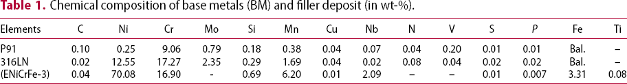
Chemical composition of base metals (BM) and filler deposit (in wt-%).
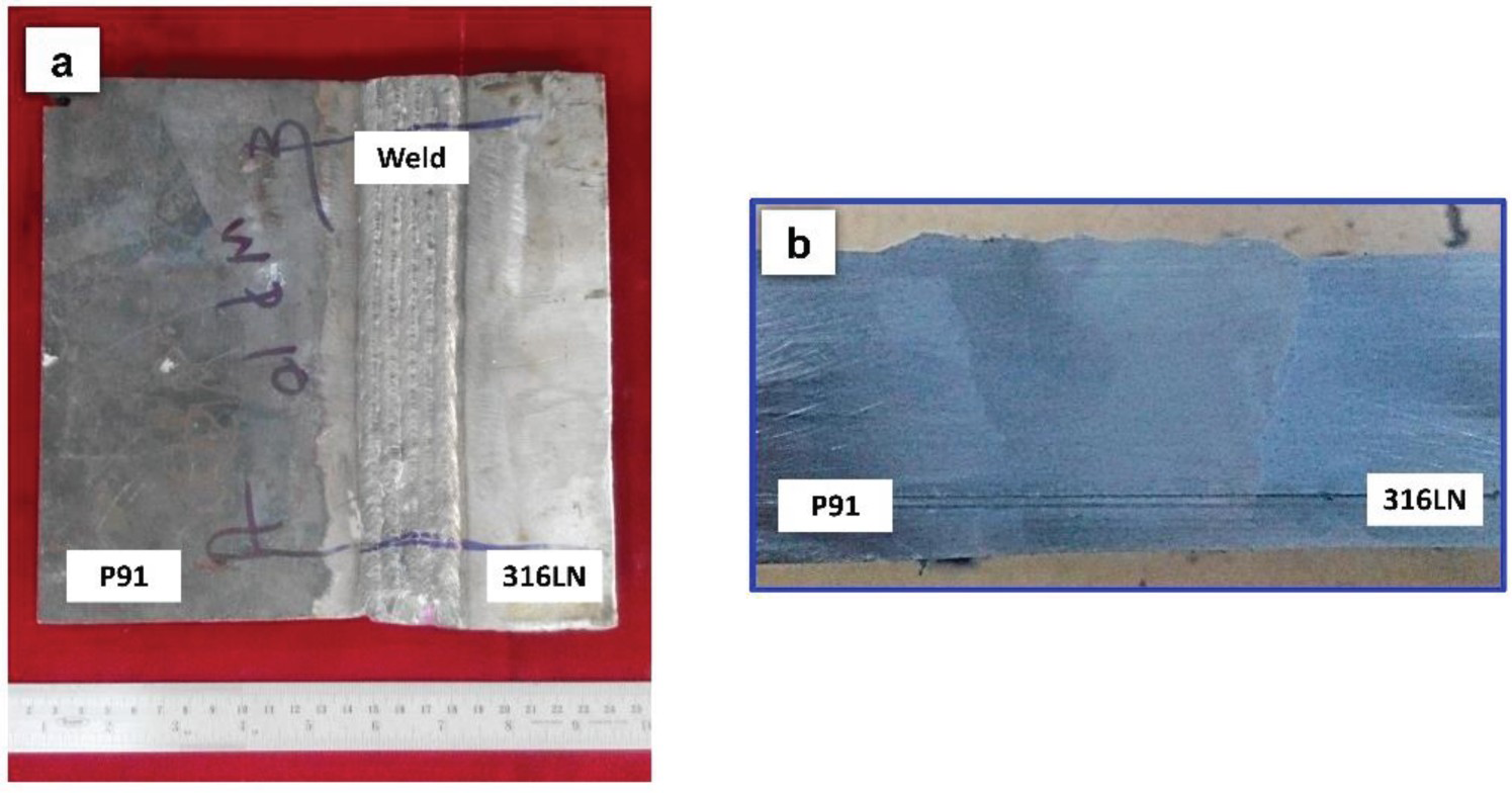
The DWJ was fabricated with a single V butt joint configuration using Manual Metal Arc Welding (MMAW) process. Joint configuration details are shown in Figure 1. First, the P91 plates were buttered with ENiCrFe-3 filler (3.15 mm dia.) to a thickness of 10 ± 0.6 mm (totally 4 layers and 20 passes for buttering). A preheat and inter-pass temperature of 250 °C was maintained (selected as per AWS D1.1 standard) throughout the process with the help of electrical strip heater. After buttering, the plates were subjected to a Stress Relief Heat Treatment (SRHT for 760 °C for 120 min.) with a heating rate of 150 °C/h followed by furnace cooling. Before welding, the buttered P91 plates were machined to ensure flatness. After machining, the average width of the buttered P91 plates was 6 ± 0.4 mm. Finally, the welding (total 12 layers and 70 passes for welding) was done between buttered P91 ferritic steel and 316 LN stainless steel in a flat horizontal position (1G position). The photograph and macrograph of DWJ are shown in Figure 2.
Details of joint configuration. (a) Photograph and (b) macrograph of the DWJ.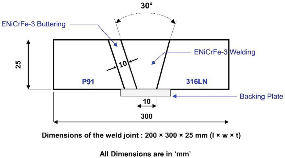
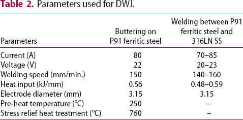
Parameters used for DWJ.
The specimens for microstructural characterisation were extracted normal to the welding direction using the wire-cut electrical discharge machining process. The scheme of extraction of samples for microstructural analysis is shown in Figure 3.
Extraction of specimens for microstructural analysis.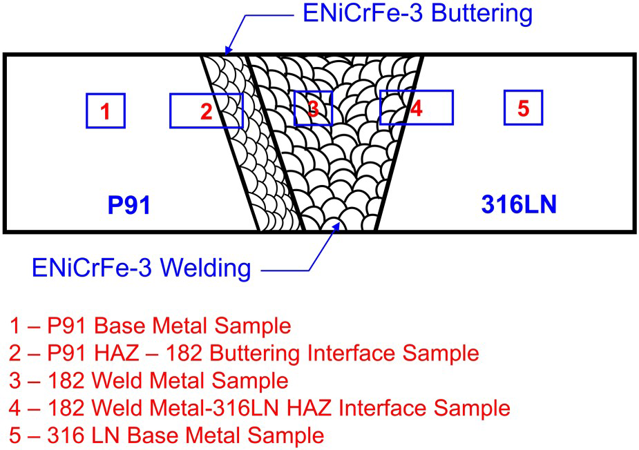
After extraction, the specimens were mounted in a conductive resin and it is grounded using a series of SiC sheets up to 3000 grid size. The final polishing was done using a diamond suspension of grid size 1 and 0.25 µm. Both optical microscopy (OM) and scanning electron microscopy equipped with Energy Dispersive Spectroscopy (SEM-EDS) specimens were etched with different etchants. For P91, Villela's reagent (mixture of 1 g of picric acid + 5 ml HCl + 95 mL ethanol) was used. Aqua regia (3:1; HCl:HNO3) was used for Inconel 182 buttering, Inconel 182 weld metal, and 316LN SS regions. The transmission electron microscope (TEM) specimens were prepared from the DMJ to understand the nature of dislocations, the morphology of secondary phase particles, and crystalline details. Samples for TEM analysis were extracted from various regions of DMJ and it was thin down to 100 µm using mechanical polishing. The twin-jet electropolishing technique was used to achieve the thickness of 0.1 µm. Electron Back Scattered Diffraction (EBSD) analysis was performed at the interface of the DWJ.
Microhardness is a non-destructive technique that will provide resistance to indentation or deformation details. This technique is useful to assess the weakest region across the weld joint. Also, it is useful to compare the mechanical properties of metals and alloys. Vicker's microhardness measurements, using a load of 100 g and a dwell time of 15 s were recorded across the DWJ. The distance between two indentations was kept as 0.5 mm for base metal to HAZ and a distance of 0.2 mm was kept for HAZ to an interface. Since the joint is having a thickness of 25 mm, the hardness profile was taken at three different locations, such as top, middle, and bottom.
Results and discussion
Microstructure of base metals and filler metal
The optical microstructure of P91 (Figure 4(a)) consists of tempered martensite covered with prior austenite grain boundaries (PAGB's). The grain diameter varies between 40 and 70 µm. The TEM image of P91 (Figure 4(b)) reveals the presence of lath martensite with dense dislocations. The average width of the lath is about 0.5 ± 0.2 µm. The secondary phase particles like M23C6 and MX types were present at the PAGB's and also within the lath boundaries (Figure 4(c)). During the normalising process (1050°C for 60 min), particles like M23C6, Fe3C, and Cr3C were precipitated in the martensite laths. The changes in the dislocations and additional carbide (NbC and V4C3) precipitation occurred during the tempering treatment of this steel. These fine particles were contributed to high-temperature stability without loss in strength when compared to its previous version (P9 steel) [22].
Microstructure of P91 – Base Metal. (a) OM of P91 BM, (b) TEM of P91 BM, and (c) TEM of P91 BM (high magnification).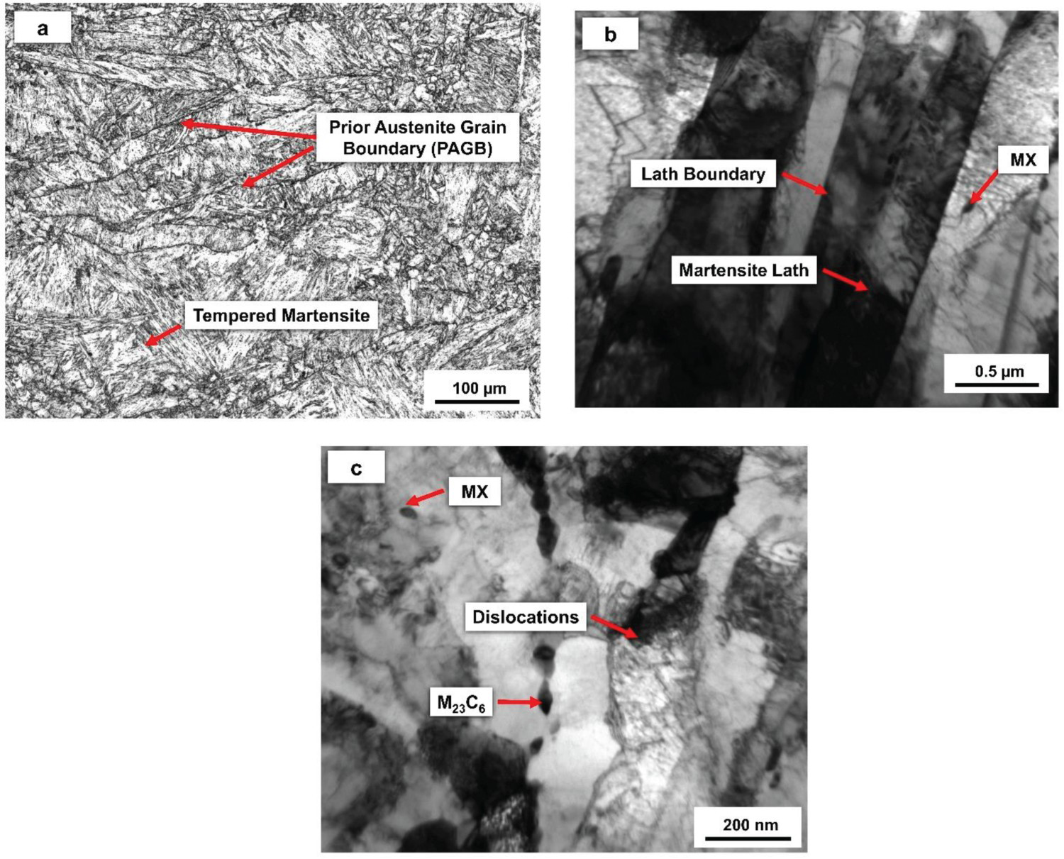
The microstructure of 316LN SS consist (Figure 5(a)) of equiaxed austenite crystals with annealing twins and small traces of δ-ferrite was evidenced at the grain boundaries in the form of stringers. The grain diameter varies between 70 and 110 µm. The TEM image (Figure 5(b)) of 316LN base metal consists of tangled dislocations along with fine secondary phase particles (mainly M23C6, Cr2C types) distributed in the austenite crystals. The addition of nitrogen in this steel enhances the tensile, yield, creep, and fatigue strength due to a decrease in stacking fault energy, solid solution hardening, and precipitation strengthening, etc. Also, the amount of nitrogen dissolved in the austenite is more than carbon due to a difference in electron exchange characteristics [23].
Microstructure of 316LN SS – Base Metal. (a) OM of 316 LN SS – BM, (b) TEM of 316LN SS BM.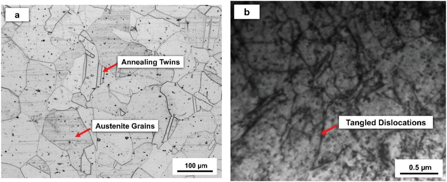
The optical microstructure of the undiluted filler deposit of ENiCrFe-3 is shown in Figure 6(a). Cellular and columnar dendrites of austenite crystals along with Solidification Grain Boundaries (SGBs), Migrated Grain Boundaries (MGBs), and Solidification Sub-grain Boundaries (SSGBs) are evidenced. The TEM image of ENiCrFe-3 (Figure 6(b)) consists of cloud-like dislocations along with secondary phase particles preferably Nb-rich compounds.
Microstructures of ENiCrFe-3 (Inconel 182) Filler Deposits. (a) OM of ENiCrFe-3 Filler Deposits, (b) TEM image of ENiCrFe-3 Filler Deposits.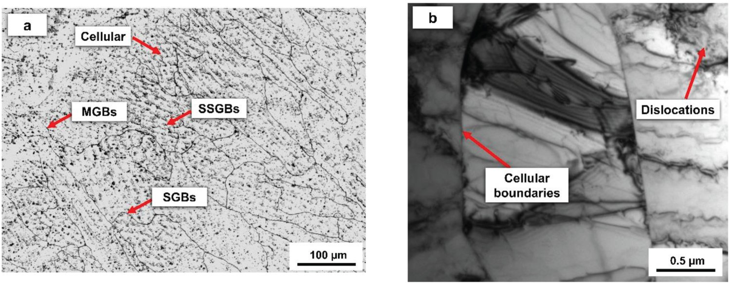
In fully austenite mode (Type A) solidification, the boundaries which disconnect cellular and columnar dendrites are known as SSGBs [24,25]. The elemental difference between matrix and SSGBs makes these boundaries visible in the austenite crystals. The SSGBs are termed as low angle grain boundaries due to minor disorientation that is derived from the cooling process. The SGBs were formed at the end of the solidification process as a result of solute atom redistribution that has both crystallographic and compositional elements. The SGBs are often referred to as high-angle grain boundaries because each group of sub-grains has a different growth direction and intersection results in high-angle misorientation. In sometimes, it is possible that the crystallographic component of SGBs to migrate away from the compositional component owing to reheating caused by multi-pass welding. The new boundary that forms with a high-angle misorientation of the parent SGBs is known as MGBs. Both SGBs and MGBs are prone to corrosion because misorientations are greater than 30 degrees [26].
Microstructures at the interface of DWJ
The optical microstructure of the P91-ENiCrFe-3 buttering layer interface is shown in Figure 7(a). Along with the fusion boundary, Type II and Type I boundaries are also visible. Type II boundary runs parallel to the fusion boundary and it is 40–50 µm away from it. Type I boundaries run perpendicular to the fusion boundary as a result of epitaxial grain growth. In general, the solidification behaviour of dissimilar weld (BCC/FCC) is different from similar weld joint (BCC/BCC). In latter type welds, the solidification begins from the edge of the base metal and grows towards the weld centreline. These are often referred to as Type I boundaries in DWJ. In dissimilar welds, Type II boundaries are formed due to solid state grain boundary migration from the austenitic temperature during the on-cooling weld thermal cycle. Another mechanism proposes Type II boundaries forms from the high-temperature γ/γ boundary that is present along the fusion boundary in DWJ [27].
Interface microstructure and EDS line scanning of P91-ENiCrFe-3 buttering layer (a) OM of P91-ENiCrFe-3 buttering layer interface, (b) OM of P91-ENiCrFe-3 buttering layer (Etched on P91 side) interface, (c) TEM image of P91-ENiCrFe-3 buttering layer interface, and (d) EDS line scanning across P91-ENiCrFe-3 buttering layer.
Figure 7(b) reveals the presence of a carbon-enriched zone close to the fusion boundary, and a carbon-depleted zone was observed away (≈20 µm) from the fusion boundary. The TEM image (Figure 7(c)) of P91 and ENiCrFe-3 buttering interface reveals a minor amount of carbon migrated from P91 side to buttering side and this migration was accelerated during SRHT than as-welded condition. The development of these zones was attributed due to the difference in the chromium concentration (nearly 7.8 wt-%) between P91 base metal and ENiCrFe-3 filler metal. Carbon migration is important in DWJ because it causes premature failure in service. Carbon has a higher affinity towards chromium that leads to the formation of chromium carbides adjacent to the fusion boundary. Even though a higher concentration is found on the buttering side (Figure 7(c)), it will form chromium-rich carbides. During post-weld heat treatment (PWHT), the carbon concentration was reduced along the fusion boundary and acted as a driving force for carbon migration from the P91 side to the buttering side. The carbon-depleted region will have lower hardness and reduced creep resistance than its surrounding [28,29].
Figure 7(d) shows the EDS line scanning across the P91-ENiCrFe-3 interface. From this scan, a sharp increase in Ni, Cr, and Mn and a decrease in Fe were observed nearly 20 µm from the fusion boundary towards the buttering side. Elements like Si and Nb vary in little quantity. The mismatch in the crystal structure (BCC to FCC) and unbalanced element gradient leads to less dilution across the fusion boundary [20].
The OM of ENiCrFe-3 weld metal and 316 LN SS interface is shown in Figure 8(a). It consists of an Unmixed Zone (UZ) to the width of 90–140 µm adjacent to the fusion boundary. This zone is not uniform throughout the thickness of the plate and has both cell and columnar dendrites. The base metal and filler metal have different chemistry, during welding, the base metal and filler metal mix with each other and are deposited as bulk weld metal. This bulk weld metal may be heterogeneous or homogeneous and this kind of composition variation is known as macrosegregation (approximately 100–200 µm wide) and this is observed in super-alloys, steels, and aluminium [30]. Many researchers reported the types of macrosegregation with different terms like UZ, intermediate zone, filler metal-depleted zone, island, and filler-depleted beach. The development of these zones is mainly attributed to the difference in the melting temperature between the filler metal and base metal.
Interface microstructure and EDS line scanning of ENiCrFe-3 weld metal and 316LN SS. (a) OM of ENiCrFe-3 weld metal and 316LN SS interface, (b) EDS line scanning across 316 LN SS -ENiCrFe-3 weld metal.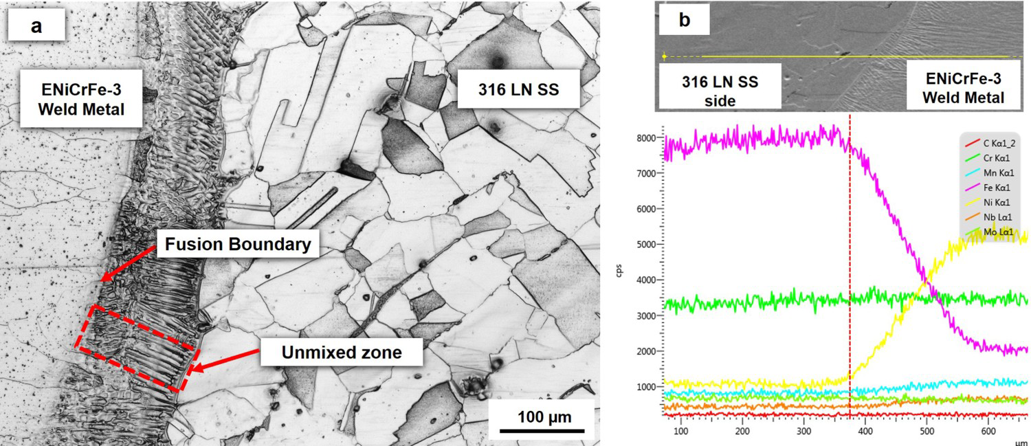
The temperature in the middle of bulk weld metal is far higher than the solidification range and results in proper mixing of the base metal and filler metal. However, the region close to the fusion line has a temperature almost close to the solidification temperature. This will cause a temperature gradient near the fusion line. The convection laminar flow will force the non-mixed base metal in that region that causes poor melting and the temperature drops below solidification leave stagnant molten metal of base metal. This stagnant molten base metal will solidify without mixing with the filler metal and produces the UZ adjacent to the fusion boundary. The chemical composition of UZ is almost similar to the base metal [31]. The EDS line scanning profile across 316LN SS base metal and ENiCrFe-3 weld metal are shown in Figure 8(b). Significant increase in Ni and decrease in Fe were evident. The concentration of chromium remains unchanged. A smooth transition of elements (Fe, Ni, and Cr) was observed due to the similar crystal structure.
EBSD scanning at the interface
The Inverse Pole Figure (IPF) and Kernel Average Misorientation (KAM) map for the interface between the P91-ENiCrFe-3 buttering layer are shown in Figure 9(a,b), respectively. IPF shows the grain orientation by colour contour [blue represents <111 > , green represents <001> and red represents <101> directions]. The KAM will be used to assess the level of residual strain using rainbow colour code [blue denotes minimum and red denotes maximum]. It gives misorientation of the grain with the surrounding grains. From IPF (Figure 9(a)), the grain orientation is random and grain growth was evident in the HAZ of P91 base metal. On the buttering side (ENiCrFe-3), epitaxial growth was evident and most of the grains were oriented in the same plane. The residual strain distribution across the fusion boundary is depicted in Figure 8(b). The intensity of residual strain is higher in the P91 HAZ region and fusion boundary and it is reduced when it moves towards the buttering side. KAM as a function of distance from the fusion boundary is shown in Figure 9(c). The misorientation is higher at the fusion boundary than HAZ. The distribution of the residual strain mainly depends on thermal cycle history, PWHT time, welding process history, and welding parameters [32].
EBSD across P91-buttering layer interface. (a) IPF, (b) KAM map, and (c) Distribution of KAM across FB.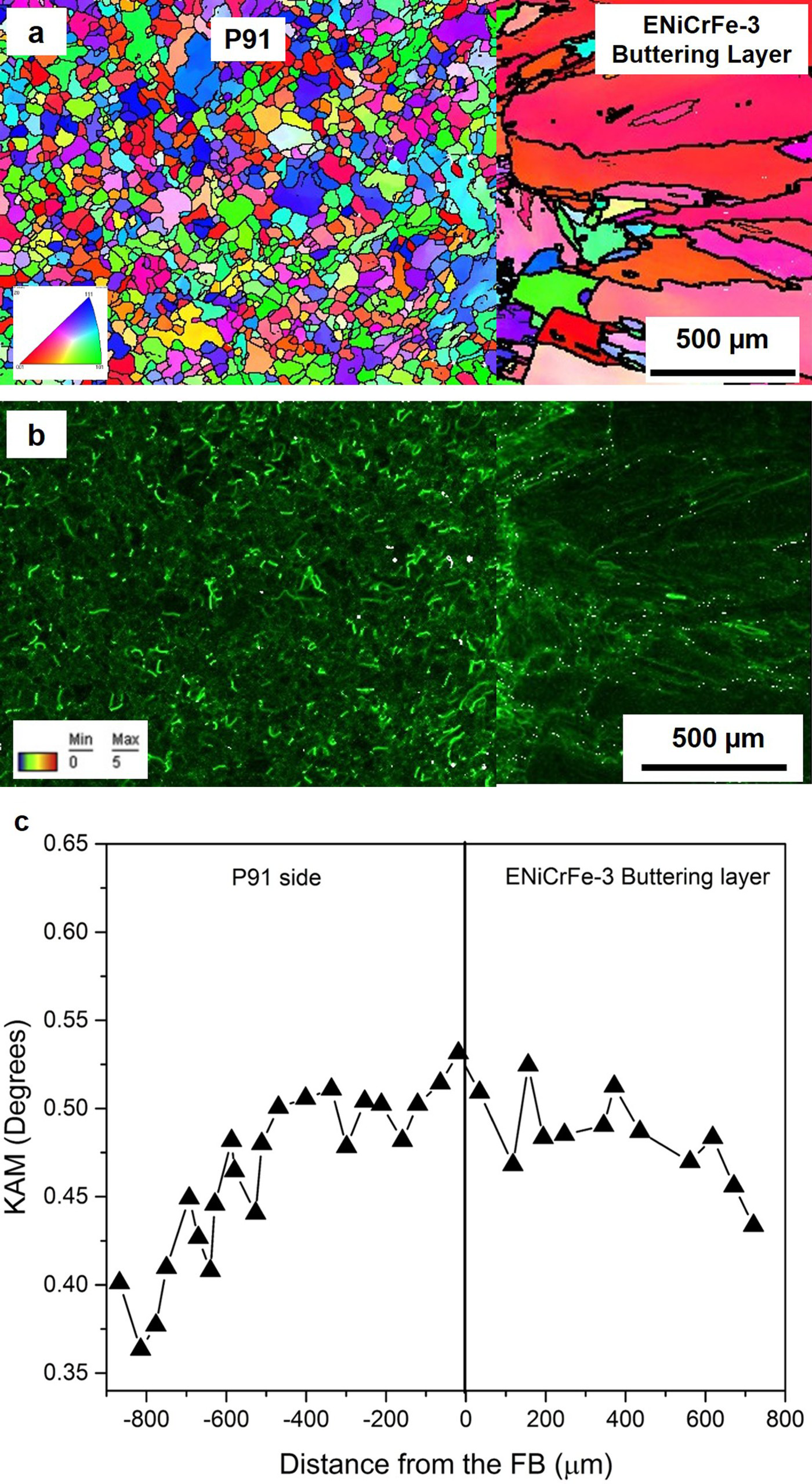
The IPF of 316LN SS and weld metal interface is shown in Figure 10(a). The grains were randomly oriented and no grain growth was observed in the HAZ of 316LN SS. Epitaxial solidification was clearly observed on the weld metal and the grains are randomly oriented. The intensity of residual strain was higher in both weld metal and HAZ of 316LN SS, which is evident from the KAM map (Figure 10(b)). The distribution of KAM across the FB is shown in Figure 10(c). The misorientation degree is higher at the interface between weld metal and HAZ of 316LN SS than at the P91 fusion boundary.
EBSD across 316LN HAZ-weld metal interface. (a) IPF, (b) KAM map, and (c) distribution of KAM across FB.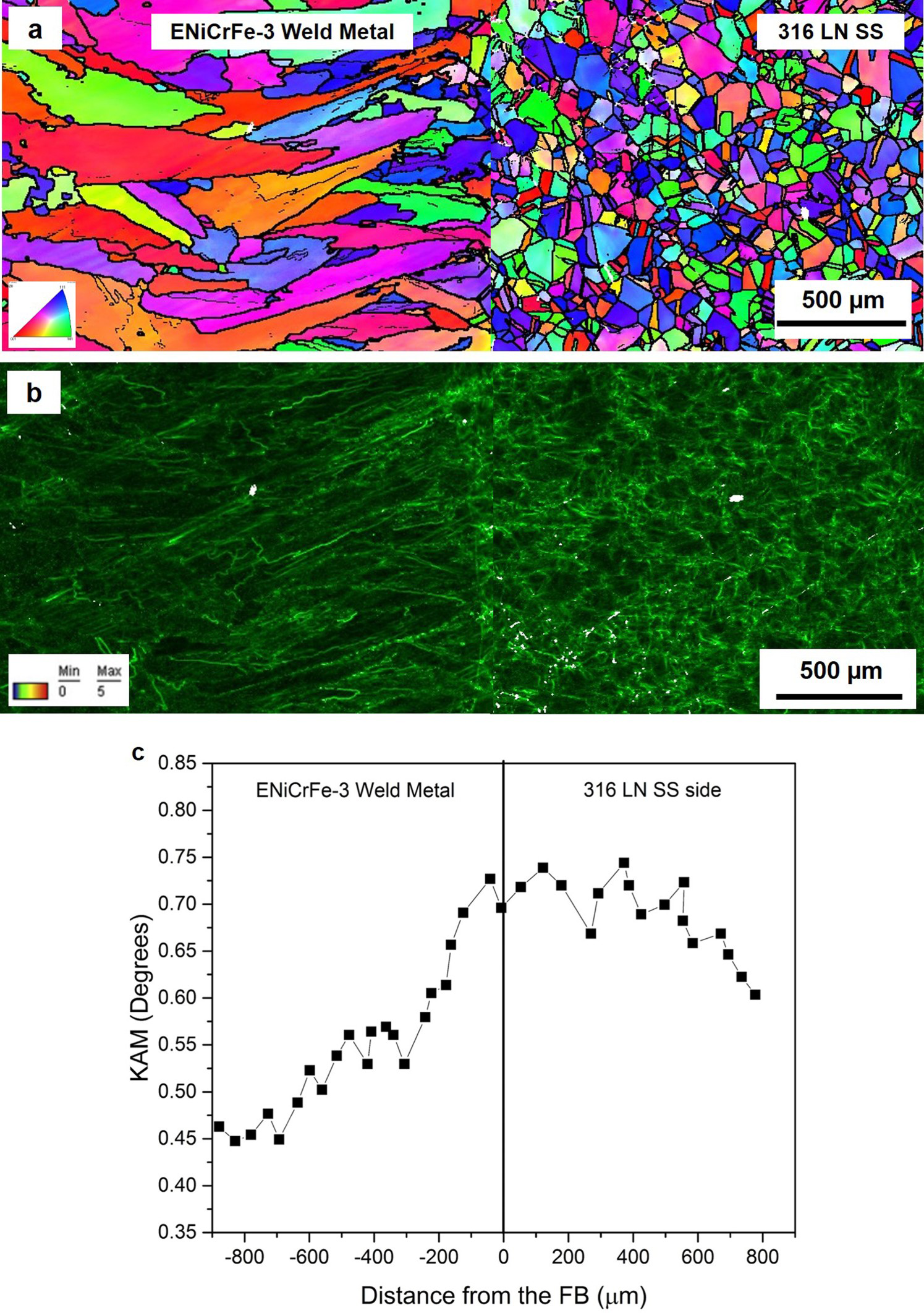
Microstructures at the HAZ region
The OM of P91 HAZ recorded close to the FB is shown in Figure 11(a). It has coarse grains (90–110 µm) with PAGBs. The TEM image of P91 HAZ captured close to the interface is depicted in Figure 11(b). It consists of a few M23C6 particles and the absence of MX type precipitates was observed. The grain diameter reduces (Figure 11(c)) when the distance from the FB increases (about 1.8 mm from the FB). The TEM image (Figure 11(d)) of this region has both the strengthening precipitates (MX and M23C6 type) with dense dislocations. The presence of soft α phase along with tempered martensite region was found (Figure 11(e)) at a distance of 4 mm from the fusion boundary.
Microstructures of HAZ of P91 side. (a) CGHAZ, (b) TEM image of CGHAZ, (c) FGHAZ, (d) TEM image of FGHAZ, (e) ICHAZ, and (f) TEM image of ICHAZ.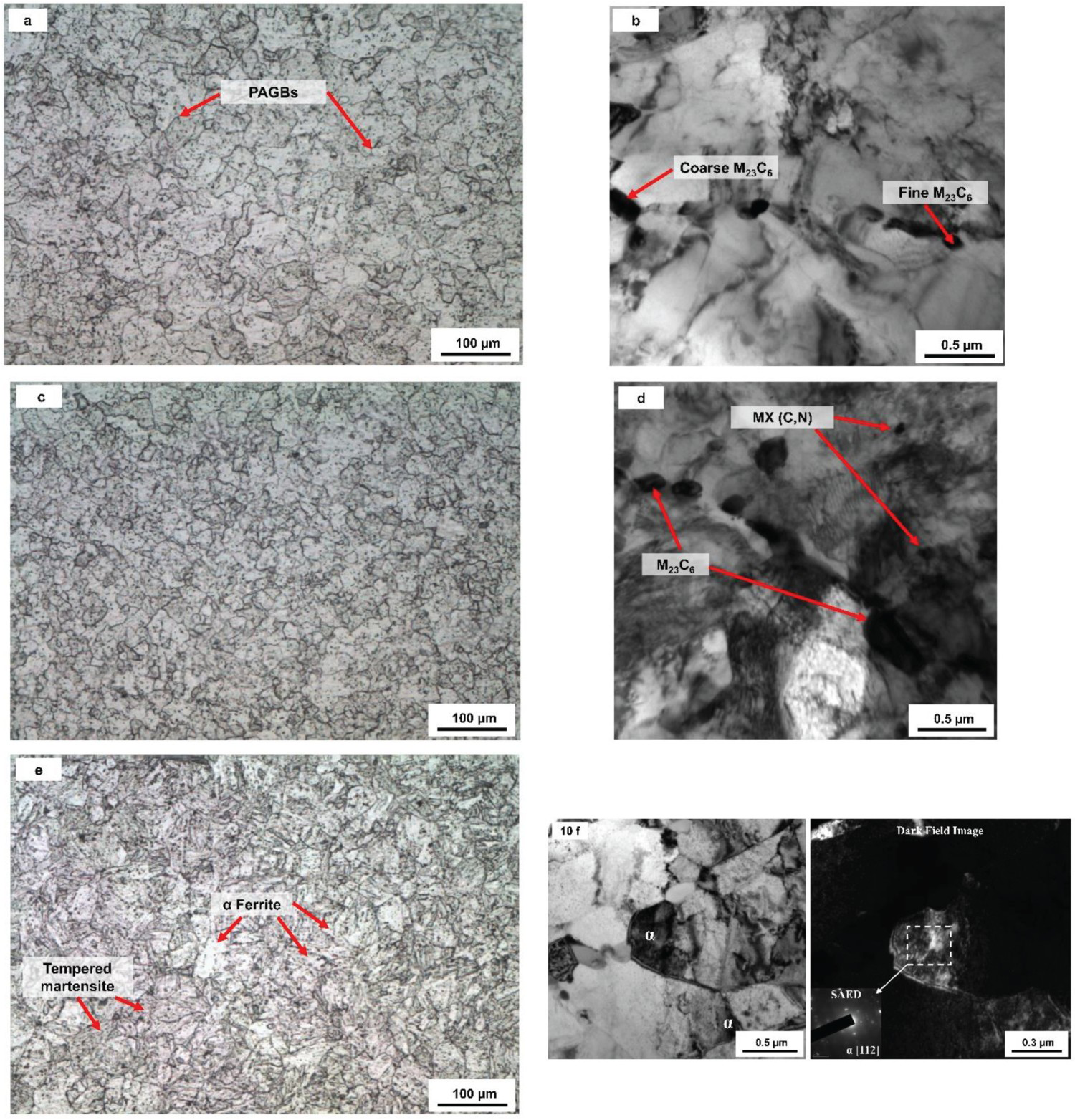
The bright-field TEM image reveals the presence of α-ferrite along with lath tempered martensite. Selected Area Electron Diffraction (SAED) confirms the presence of soft α-ferrite phase oriented in [1 1 2] direction.
Distinct HAZ developed in P91 steel is due to the high thermal conductivity nature. The entire HAZ in this steel has been divided into three different regions, namely, Coarse Grain HAZ (CGHAZ), Fine Grain HAZ (FGHAZ), and Inter-Critical HAZ (ICHAZ). The development of these regions is mainly attributed to the local thermal history experienced by these regions. Each region offers different mechanical properties and microstructures. The region close to the fusion interface experiences a temperature above Ac3 (∼1100°C) and results in the complete dissolution of carbides and nitrides. The absence of MX type and M23C6 type particles will allow the grains to grow freely and result in CGHAZ (Figure 11(a)). But, from the TEM image, very few carbide particles were observed along PAGBs that retain strength for this region. Few researchers [33,34] observed δ ferrite patches in CGHAZ that will deteriorate the mechanical properties at high temperature, but it was not observed in this investigation because of reduced heat input achieved by the filler-added process. The peak temperature decreases (950°C) when the distance from FB towards base metal increases. At this temperature, very few particles were dissolved in the matrix and the existence of un-dissolved particles pinned with dislocations impedes the grain growth and results in the formation of FGHAZ (Figure 11(c,d)). The interface between HAZ and base metal experiences the temperature between Ac1 and Ac3 resulted in the partial transformation of austenite. During cooling, it solidifies as un-tempered martensite along with α-ferrite (Figure 11(e,f)). The formation of this α-ferrite along with un-tempered martensite makes ICHAZ a weaker region across the DWJ [19]. The cross weld tensile test results confirm that the failure occurs at ICHAZ and this type of failure is referred to as type IV cracking [7,11,35,36].
The OM of 316 LN SS-HAZ is shown in Figure 12(a). There is no appreciable variation in the morphology of HAZ and it is the same as the base metal. However, the TEM image (Figure 12(b)) reveals the tangled dislocations get accumulated in the grain boundary that leads to HAZ hardening. The HAZ hardening phenomenon is consistent with the distribution of misorientation across the FB. The repeated thermal cycle experienced in HAZ due to multi-pass welding increases the residual strain and hardness at the HAZ of SS [7,37].
Microstructures of HAZ of 316LN SS. (a) OM of 316 LN SS HAZ and (b) TEM image of 316 LN SS HAZ.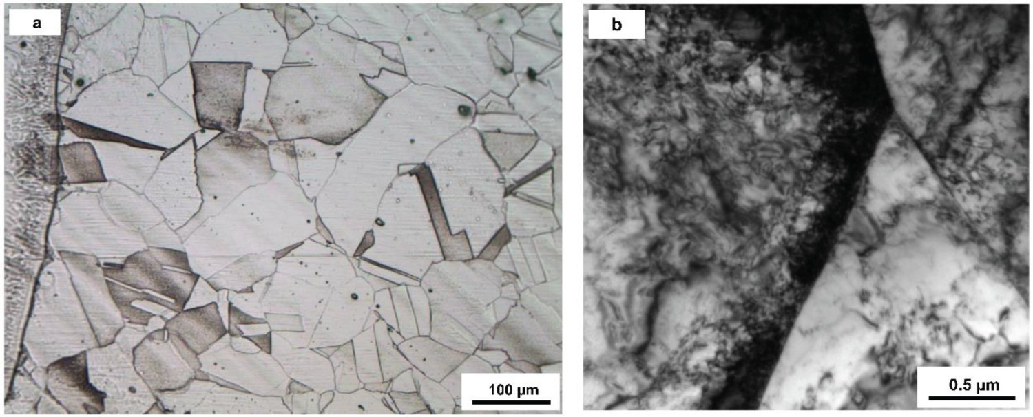
Microhardness variation across DWJ
The microhardness distribution across DWJ is shown in Figure 13. Since the joint thickness is 25 mm, the hardness is recorded in three regions, namely, top, middle and bottom. Non-uniform hardness distribution is observed across the joint and a peak value of 252 HV is observed at the interface between P91 HAZ and ENiCrFe-3 buttering layer. The hardness of base metals is almost the same (around 210–220 HV). Even though grain orientation is different for buttering layer and weld metal, it does not reflect in the hardness value. The HAZ of the P91 side close to the fusion boundary has higher hardness, and it is decreased when moving towards base metal. This is due to the carbon migration, lath structure within PAGBs, and development of residual strain due to change in chemistry from base metal (P91) to filler metal [38]. The lowest hardness of 189 HV was observed at the HAZ – base metal interface. This dip in the hardness may be due to the presence of the soft α-ferrite phase at the ICHAZ. The HAZ of 316 LN SS is narrow (∼2.5 mm) than the P91 side (∼4 mm) due to the lower thermal conductivity of SS. Repeated tempering caused by multi-pass welding, increased misorientation angle, accumulation of tangled dislocation at the grain boundary increases the hardness for 316 LN than the base metal.
Microhardness distribution across DWJ.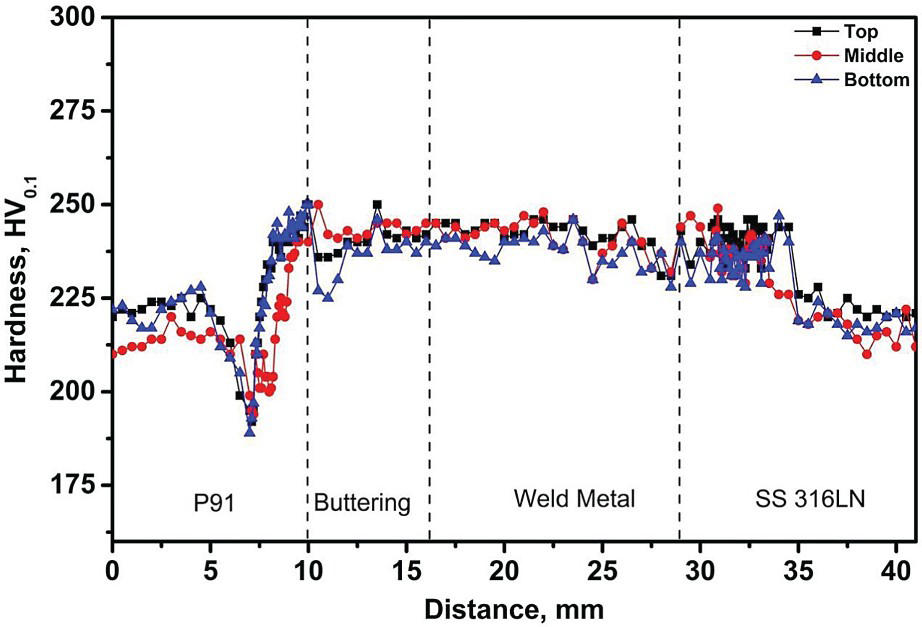
Conclusions
The microstructural features of the dissimilar weld joint between P91 ferritic steel and 316 LN stainless steel with ENiCrFe-3 filler metal have been characterised by OM, TEM, and SEM. Also, a microhardness test was conducted across the dissimilar weld joint. From this investigation, the important conclusions are,
A complex microstructure was developed at the interface of the dissimilar weld joint. Mismatch in the chromium concentration, change in primary mode solidification, and difference in the melting temperature between the base metal and filler metal may be the reason for the development of complex microstructures at the interface. The distribution of misorientation and intensity of residual strain is higher for ENiCrFe-3 weld metal-316 LN stainless steel HAZ interface than P91 HAZ-ENiCrFe-3 buttering layer interface. Multi-pass welding causes repeated tempering leads to higher intensity of residual strain, whereas stress-relieving heat treatment was done after buttering may reduce the intensity. Distinct microstructures were developed at the P91 HAZ region due to peak temperature attained in each region during the buttering process and a soft zone was found at the P91 HAZ – base metal interface. For the 316 LN stainless steel HAZ region, there is no drastic change in the grain size and the morphology of the grains remains the same. The distribution of hardness is found to be uneven across the dissimilar weld joint and peak hardness was observed at the P91 HAZ–ENiCrFe-3 buttering layer interface. Also, a sharp decrease in the hardness is found at the P91 HAZ – the base metal interface that is located approximately 4 mm from the fusion boundary. The hardness for HAZ of 316LN stainless steel is higher than the base metal.
Footnotes
Disclosure statement
No potential conflict of interest was reported by the author(s).