
Abstract
Three TWIP steels based on the composition Fe-23Mn-3Si-3.3Al with different carbon concentrations were examined. The alloys were produced by rapid solidification in an experimental apparatus designed to simulate direct strip casting conditions. Examination of the driving force for solidification for this alloy showed the preference for BCC and FCC solidification were very close for this composition, within 10% of one another. This factor combined with the high undercooling resulted in the change in the primary solidified phase. Chemical analysis of the as-cast strip showed inter-dendritic segregation of Si and Al, but negligible segregation of Mn. A simple heat treatment was sufficient to chemically homogenise all alloys and produce microstructures comprising a fully austenitic structure, consistent with thermodynamic predictions.
Keywords
Introduction
The demand for high performance steel in the automotive industry has been increasing steadily over the past decades [1-4]. This is because high performance steels can improve crash-worthiness and decrease the weight of the vehicle, leading to reduced fuel consumption. Direct strip casting (DSC) is a relatively new ‘green’ technology that forms a solid steel sheet from the liquid in one step [5]. This processing route leads to extremely rapid solidification and the creation of non-equilibrium microstructures [6] and unusual grain morphologies during secondary processing [7,8]. Cooling rates experienced during strip casting are highest at the first contact between the liquid steel and the cold substrate, and at this time have cooling rates reported to be as high as 103–105 °C s−1 [9,10], somewhat similar to the cooling rates experienced during modern 3D printing processes, such as direct energy deposition [11]. One of the advantages of this rapid cooling is a reduction in inter-dendritic segregation [6,12] and a reduction in the as-cast grain size [5]. Due to the non-equilibrium nature of the cooling rate, the microstructural development and mechanical properties of many steel grades under these conditions is not yet known. The present paper investigates the behaviour of twinning-induced plasticity (TWIP) steels produced by strip casting. These steels examined here contain 3 wt% silicon, 3.3 wt% aluminium, 23 wt% manganese and 0–0.4 wt% carbon. Under conventional processing the high manganese content of these steels is known to cause a number of issues. In particular the manganese is known to heavily segregate to the centreline of the slab, and cannot be easily homogenised [13]. This has been reported to result in a reduction in mechanical properties of the sheet [6]. It is expected that the level of segregation could be radically reduced under rapid solidification conditions, and that this could lead to new strip products with improved properties.
In the present paper, a high manganese TWIP steel was fabricated using a simulated DSC process [9,14]. This process simulates the rapid solidification that occurs during the initial contact between the liquid steel and the rotating copper rolls. The high cooling rates experienced result in non-equilibrium solidification, and this is discussed in terms of composition, the thermodynamics of solidification, and the need for secondary processing.
Experimental work
Design of specimen compositions
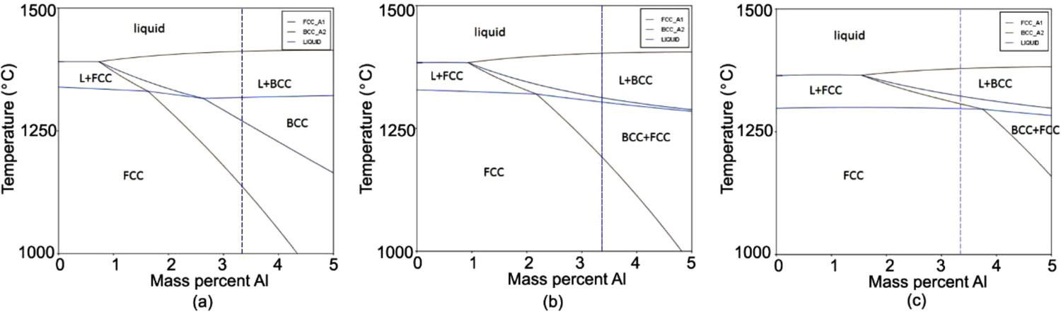
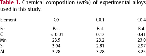
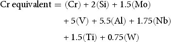
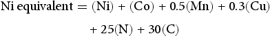
The compositions of the experimental samples are listed in Table 1. The alloy compositions in Table 1 were chosen by referring to the Schaeffler diagram [15] (Figure 1), utilising the nickel and chromium equivalents described by equations 1 and 2. This diagram was developed by the welding community, and describes what microstructure might be expected from rapid cooling of a given composition from a temperature of 1100 °C. It can be seen that the chosen compositions, with their variation in carbon content, would be predicted to form either fully austenitic microstructures, or a mixtures of ferrite and austenite. The expected phases that will form after homogenisation can be predicted either experimentally using a Schaeffler diagram or theoretically using thermodynamic calculation. Thermodynamic predictions for the equilibrium phase fraction for the alloys examined here are shown in Figure 2. It can be seen the equilibrium phases predicted to occur after homogenisation are fully austenitic.
Schaeffler diagram used to determine the sample compositions. Blue dots indicate the region for C0, C0.1 and C0.4 steels. A, F and M indicates the austenite, ferrite and martensite, respectively [15]. Phase diagram of studied alloy as a function of Al content for (a) C0 (b) C0.1 and (c) C0.4 steel. The composition of Al is 3.3 wt%. Chemical composition (wt%) of experimental alloys used in this study.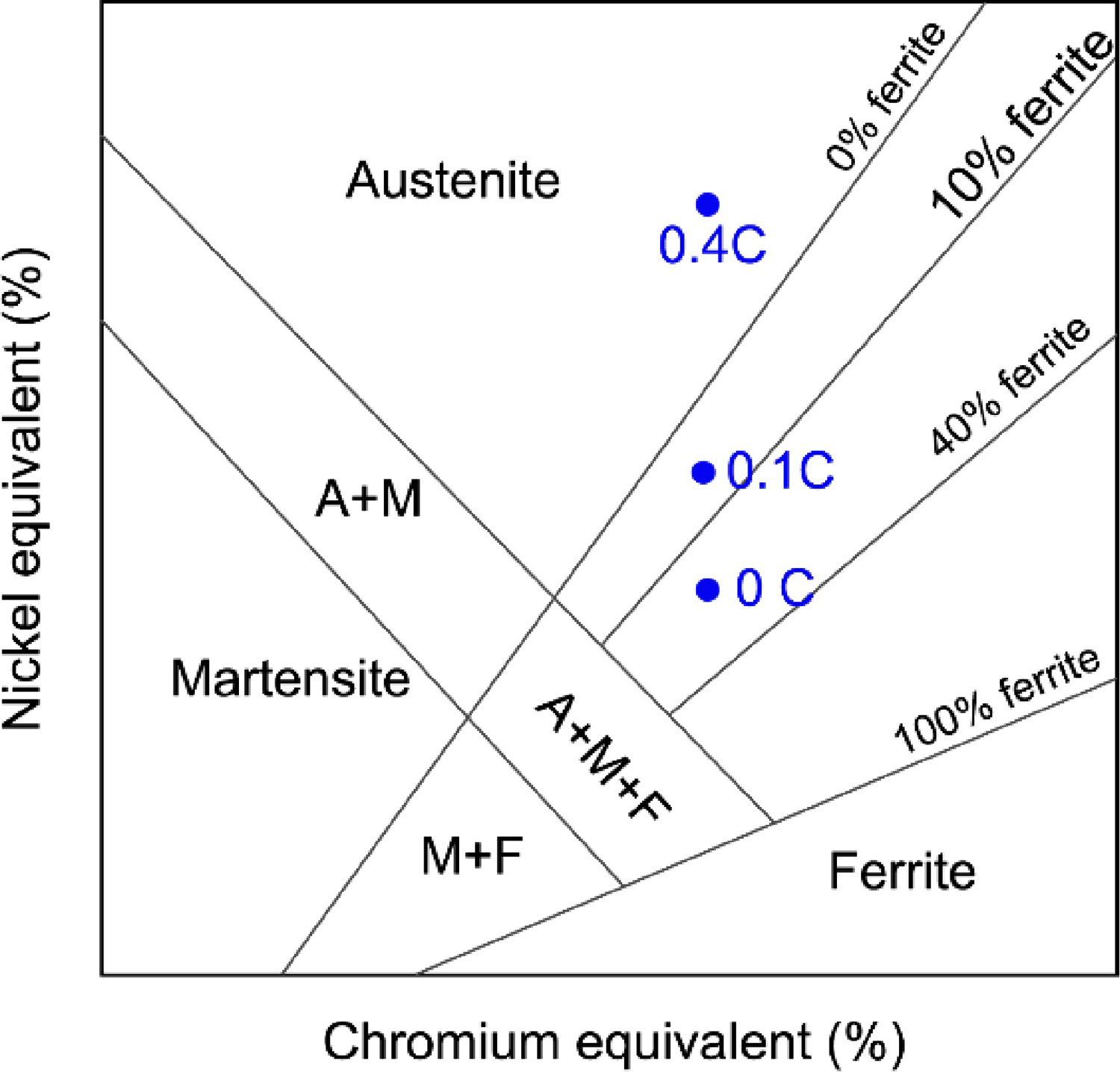
The chromium and nickel equivalents are used to calculate the possible regions of the proposed compositions in wt% [15].
Sample fabrication via the dip testing method
Samples were fabricated by firstly melting the raw elements in a 100 kg induction furnace. A dip tester was utilised to fabricate all samples, and is described in detail elsewhere [9,14]. Experiments were carried out at a melt temperature of 1525 °C (±10 °C). The melt temperature was constantly monitored by a thermocouple located 40–50 mm below the melt surface. The paddle was programmed to immerse and retract rapidly at a velocity of 60 m·min−1. The average residence time of the paddle in the melt was around 0.2 s. During the immersion and retraction sequence, to avoid induction field interference with the substrate thermocouple and to avoid induction heating of the paddle, the furnace was turned off seconds before the immersion. Once the paddle was retracted from the melt, the cooling gas in the paddle was turned on and the solidified samples were carefully removed from the substrate. The substrate was then cleaned with a wire brush to remove any oxide layer before the next immersion cycle. The samples were then collected in the form of steel coupons solidified onto the substrates. Each of the copper substrates had a dimension of 35 mm (width) × 35 mm (length). The thickness of the as-cast samples varied between 2 and 2.5 mm. Five dips were performed for each sample.
Microstructure observation
All three samples of the as-cast samples were first cut into smaller pieces with a dimension around 10 mm × 5 mm and were hot mounted for the microstructural examination. The samples were polished using 6, 3, 1 µm diamond paste and finally with oxide polishing suspension (OPS) solution.
Scanning electron microscopy was carried out using a Zeiss Supra-55VP FEG SEM, operated at a voltage of 20 kV. The backscatter working distance was set to around 6 mm for all samples. Electron backscatter diffraction (EBSD) was performed using the HKL-Flamenco or HKL-Aztec acquisition software interfaced to a Zeiss LEO-1530 FEG SEM. A working distance of ∼10 mm and a sample tilt of 70° were employed.
The element mapping was conducted by Energy dispersive spectroscopy (EDS) using a JEOL JSM-7800F FEG SEM. The working distance applied in this process was 13 mm at an accelerating voltage of 10 kV.
X-ray diffraction (XRD)
Samples were examined using a Panalytical X-pert Pro MRD XL. Point focus and copper Kα radiation (λ = 1.54 Å, V = 40 kV, and I = 30 mA) were used for the analysis. The data was collected at angles between 40° and 140°, with a 0.02° step size and 1 second collection time per step. The spot size was set to 8 × 8 mm. For quantitative analysis, the TOPAS (Total Pattern Analysis Solution) PROGRAM was used.
Homogenisation
A homogenisation heat treatment was performed to all as-cast samples in a high temperature muffle furnace under controlled argon (Ar) atmosphere. The samples were heated to 1000 °C for 1 hour and slow cooled to 550 °C in the furnace under controlled argon (Ar) atmosphere and held for 2 hours.
Results
Phase analysis using XRD
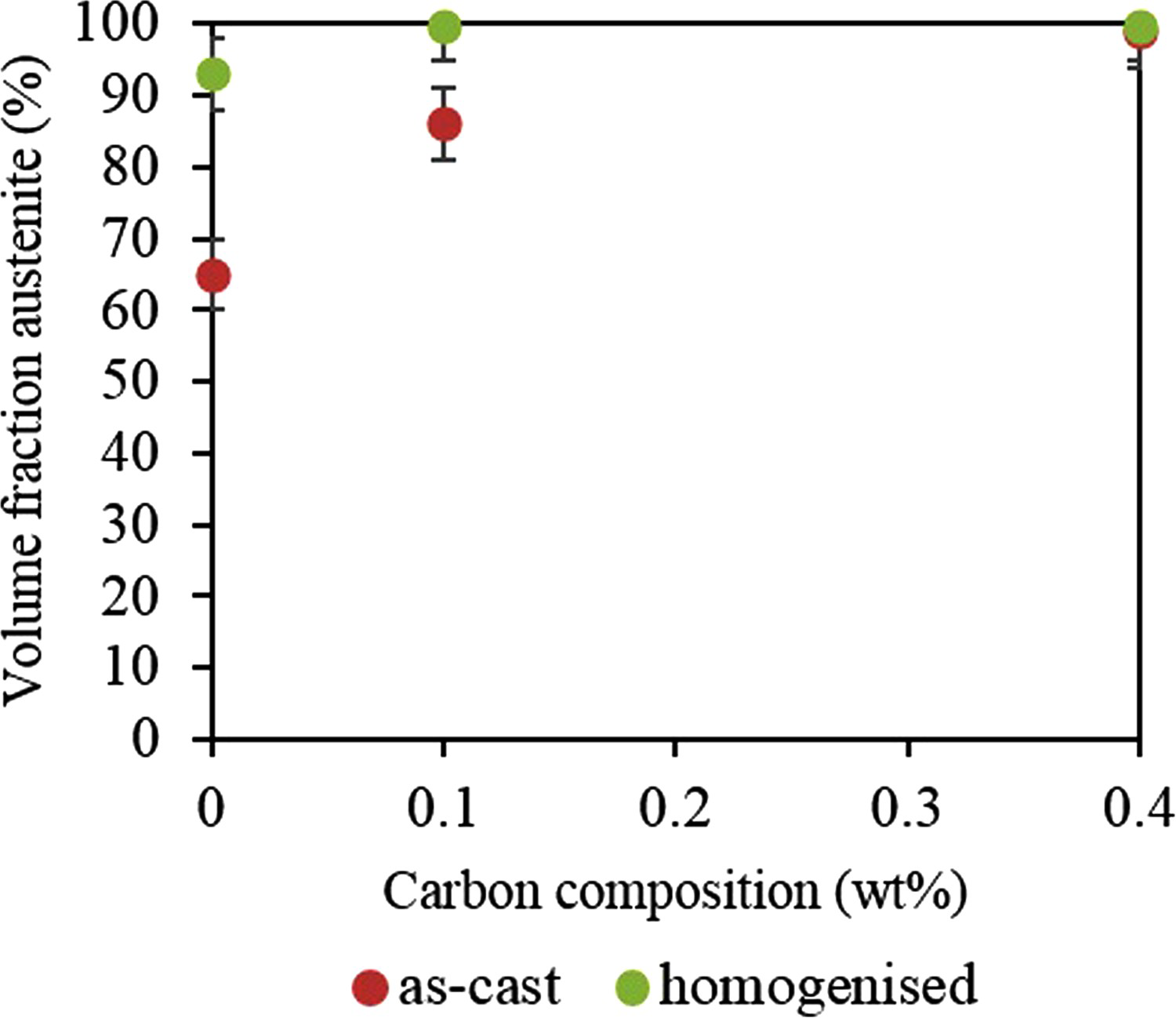
XRD was used to quantify the phase fractions of the samples. The diffractograms for all three as-cast samples, along with samples after the homogenisation treatment are shown in Figure 3. The volume fraction of face centred cubic (FCC) and body centred cubic (BCC) phases was quantified using the Rietveld refinement method, and the results of this analysis are shown in Figure 4. It can be seen that in the as-cast condition the low-carbon samples show a large amount of ferrite, but after homogenisation, all specimens are mainly austenitic.
X-ray diffraction spectrum of the (a) as-cast and (b) after homogenisation treatment samples. The austenite volume fraction of the three compositions based on the XRD analysis.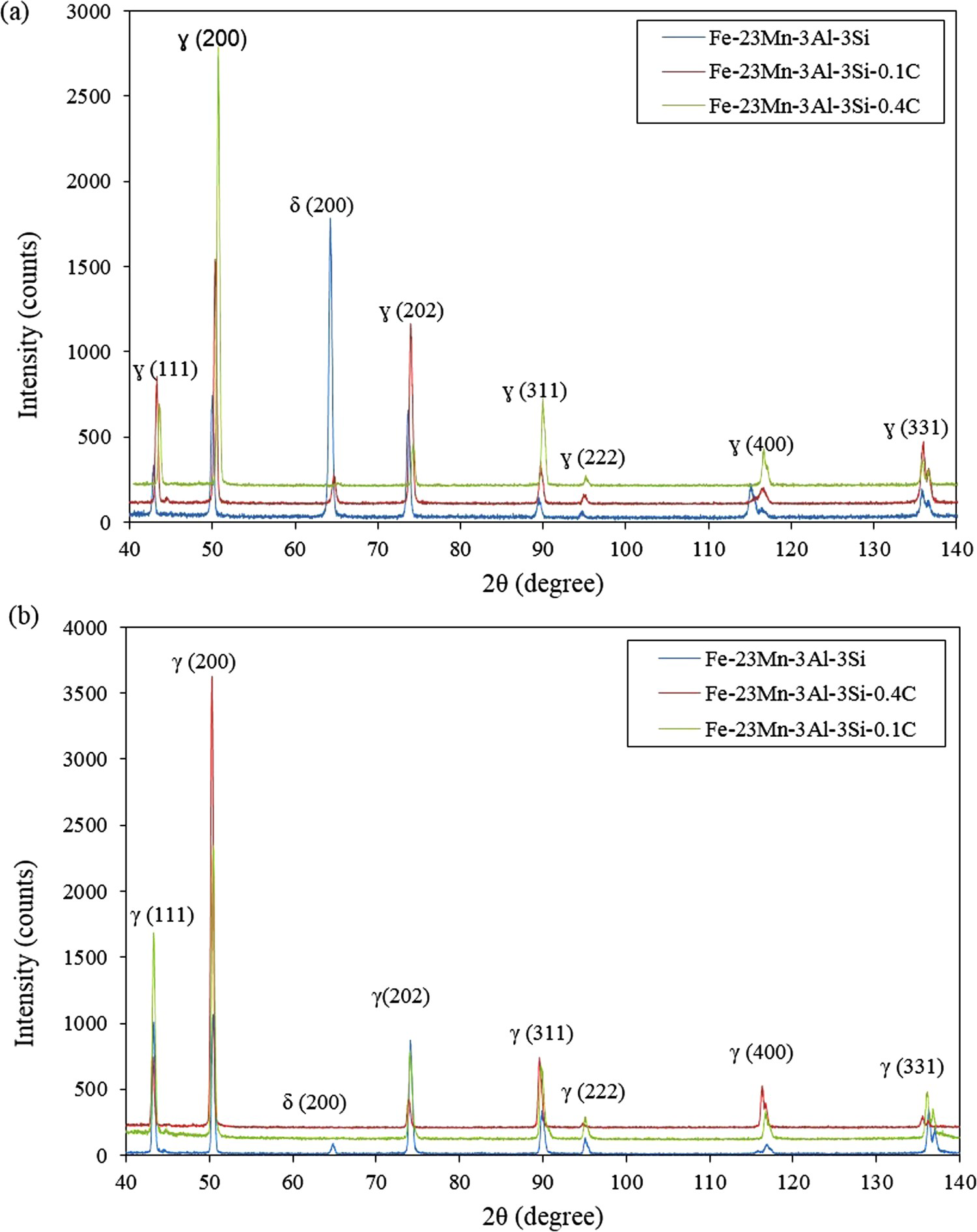
Microstructure of the as-cast condition
The microstructure was investigated using EBSD (Figure 5). The carbon-free steel shows a mixture of coarse BCC grains and finer FCC islands (Figure 5(a)). With increasing carbon concentration (Figure 5(b) and (c)), the volume fraction of FCC increased, which was consistent with the XRD results. With increasing carbon content the small lath-like FCC grains evolve towards larger globular grains with small amounts of ferrite in the inter-dendritic regions. The steel with 0.4 wt% carbon shows a noticeable change in austenite morphology throughout the strip thickness, with the grains increasing in size with distance from the substrate.
EBSD micrographs of the as-cast (a) C0 steel (b) C0.1 steel and (c) C0.4 steel. The solidification direction is towards the bottom of the page. The inset (d) shows the dendritic morphology of the band contrast map within an individual grain.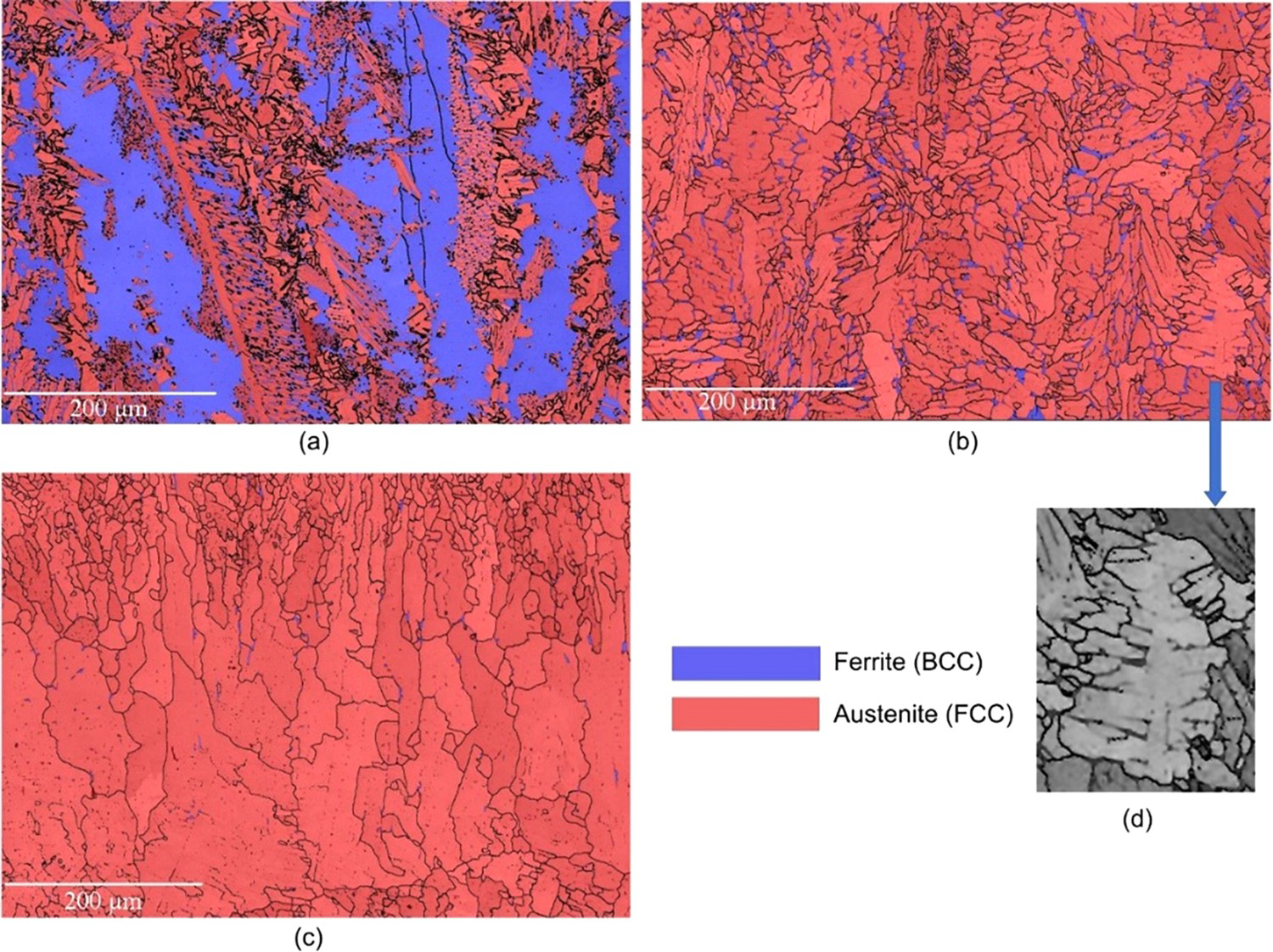
Higher magnification imaging revealed the presence of 0.5–1 µm size particles in all three steels (Figure 6). It was found by EDS that the inclusions were enriched with sulphur, nitrogen and aluminium, (Figure 6(a)–(c)). A summary of the observations is provided in Table 2. The EDS analysis also revealed chemical segregation within the inter-dendritic regions, with aluminium and silicon found to partition to the inter-dendritic regions more strongly than the other elements (Figure 6(a)–(c)).
EDS micrograph of the as-cast C0.4 steel. Type of solute segregation and particles that were chemically identified using EDS mapping.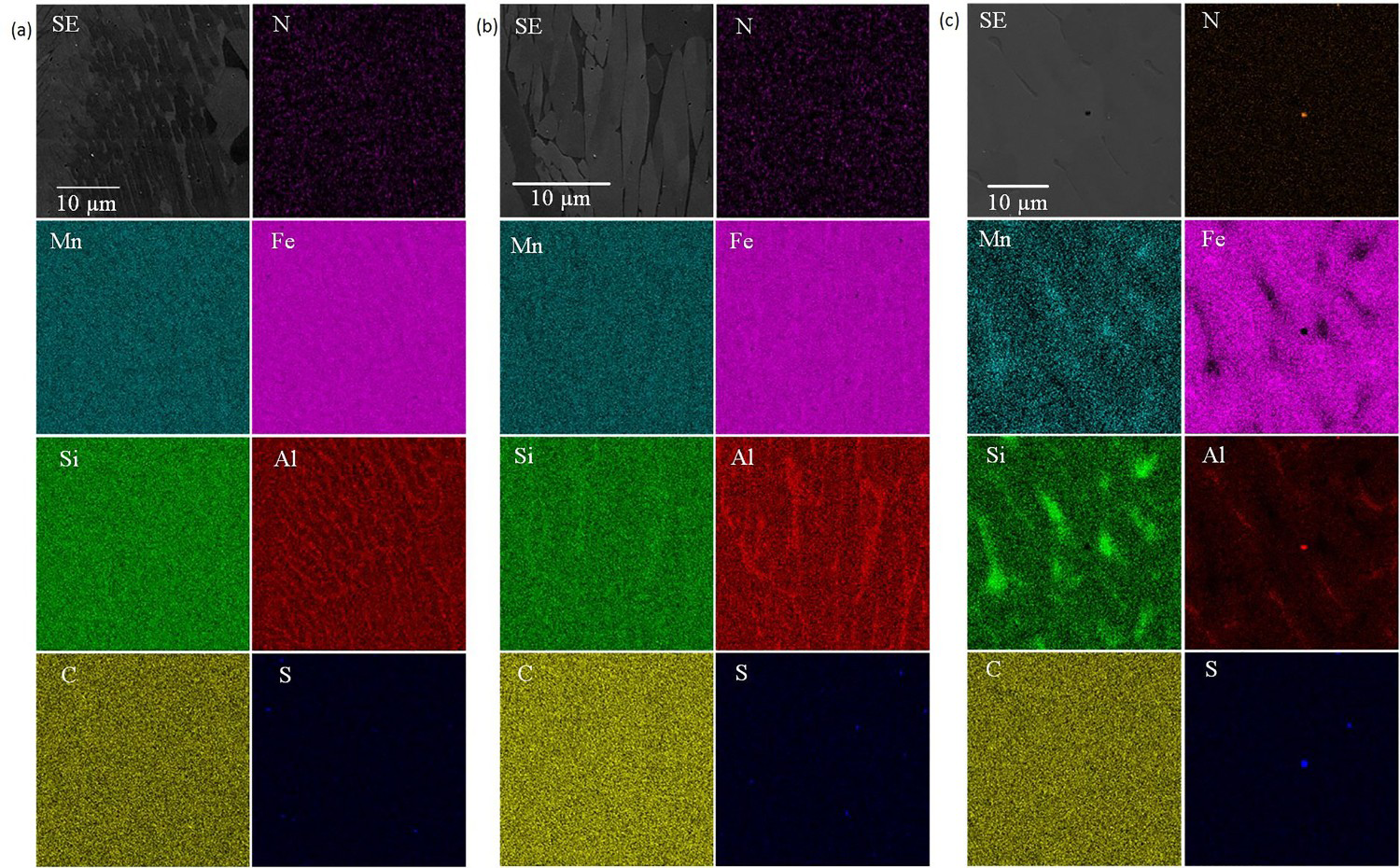
Microstructure of the homogenised specimens
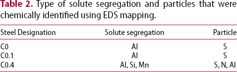
The EBSD maps of the homogenised alloy are presented in Figure 7. The specimens were all found to be austenitic, consistent with the XRD data (Figure 2). Chemical mapping showed that the homogenisation treatment had removed the chemical segregation from the inter-dendritic regions, and that the number of Aluminium-rich precipitates had increased (Figure 8).
EBSD micrographs of the homogenised (a) C0 steel (b) C0.1 and (c) C0.4 steel. Red area indicates the austenite phase and blue region indicates the ferrite phase. EDS micrograph of the homogenised C0.4 steel.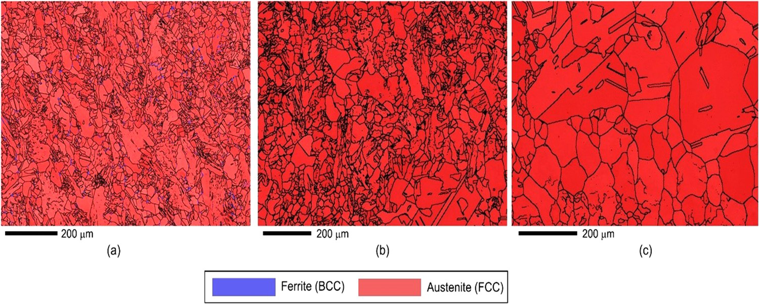
Discussion
The solidification sequence
The thermodynamic predictions shown in Figure 2 indicate that the equilibrium solidification sequence for these three alloys follows:
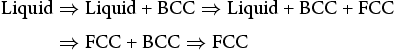
Figure 5 shows that for the carbon-free specimen, the alloy solidified first as ferrite (the blue phase in Figure 5). This is evidenced by the large columnar grains indicative of the as-solidified structure in these strip casting simulations [14,16-18]. Upon further cooling, the specimen then underwent partial solid state phase transformation from ferrite to austenite, developing classical Widmanst¨atten shaped austenite colonies. The two alloys with higher carbon concentrations showed very different microstructures, and solidified directly into austenite. This is consistent with the dendritic features within the microstructures, such as those shown in the inset in Figure 5, as well as the backscattered imaging that shows a classical as-cast appearance (Figure 9). The imaging in Figure 9(a) and (b) look markedly different. In the case of Figure 9(a), the alloy solidified as austenite, and in the inter-dendritic regions, some ferrite was formed due to partitioning of aluminium to the inter-dendritic regions (see Figure 5(b)). There is also some indication of austenite films between ferrite laths, but this was too small to image with EBSD. In the case of Figure 9(b), the alloy in this case also solidified directly into austenite but did not undergo further transformation during cooling. In this alloy, which had the higher carbon content, no ferrite was formed in the inter-dendritic regions, so the microstructure retains the classical as-cast appearance, and remains fully austenitic at room temperature.
Electron micrographs of the as-cast structure of the (a) 0.1% carbon and (b) 0.4% carbon specimens.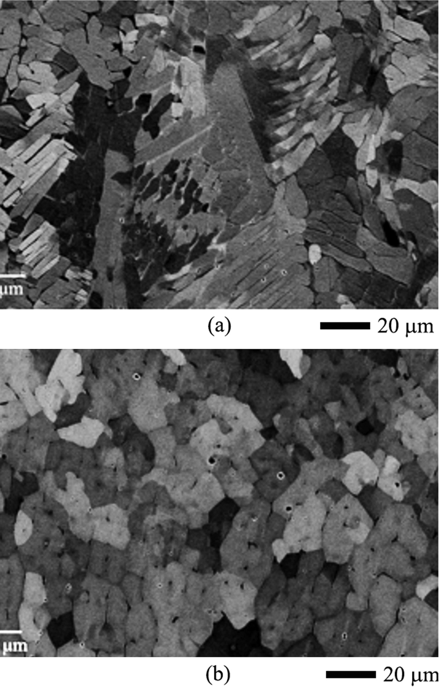
At equilibrium, all three alloys are predicted to be austenite below ∼1100 °C (Figure 2), while solidification predictions (Figure 10) indicate that these alloys should all solidify firstly as BCC, followed by a solid state phase transformation to FCC upon further cooling. Although the carbon-free alloy showed BCC solidification, the other 2 alloys did not. It is now pertinent to examine why.
Thermodynamic simulation of the equilibrium solidification of the three alloys examined here.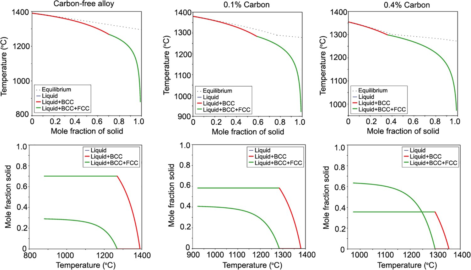
If we consider the driving force (D) for the formation of FCC and BCC from the liquid, it can be seen that the driving force for the formation of each of these phases is very close, Figure 11(a). This is further interrogated in Figure 11(b) where the delta driving force (ΔD), the driving force for BCC minus the driving force for formation of FCC phases, is shown as a function of temperature. Where ΔD is positive, the BCC phase is preferred; where ΔD is negative, the formation of FCC is preferred. The error bars in ΔD were determined assuming a composition variation in the liquid corresponding to 10% solidification. The compositional fluctuation is likely to be much larger than this close to the solidification front. It can be seen from Figure 11(b) that at ∼1000 °C the carbon-free composition has a minimum value of ΔD (the orange curve), and that the addition of carbon (the blue curve) further reduced ΔD. This analysis indicates that the FCC phase may become the preferred phase, particularly at large undercoolings.
(a) Driving force (D) for the formation of FCC and BCC from the liquid and (b) delta driving force (ΔD) of the samples.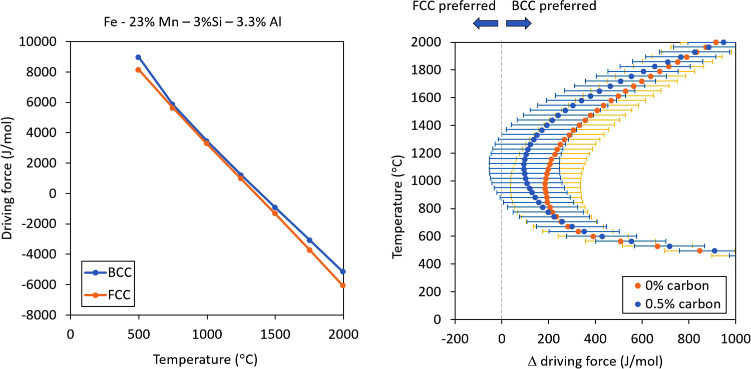
There are several reports in the literature where stainless steel alloys do not solidify in their equilibrium phase during rapid cooling [19-21]. Examples include 316 [22] and 308 stainless steels [23] that can change the primary solidified phase from ferrite to austenite with increased cooling rate. This behaviour has been previously suggested to be due to an increase in the dendrite tip undercooling at large solidification speeds [23]. In the present case we present a thermodynamic model that addresses nucleation of the solidified phase, rather than the preferred phase during growth. Both are likely to contribute to the experimental observation of non-equilibrium primary solidified phases at high cooling rates.
Effect of homogenisation on austenite morphology
The effect of homogenisation on the volume fraction of austenite is shown in Figure 4. It can be seen that the austenite volume fraction increased after the homogenisation treatment which is consistent with the thermodynamic prediction of FCC being the stable phase at 1000 °C after homogenisation of the alloy. Of more interest to the TWIP/TRIP steel community is the chemical micro-segregation in these alloys. In the present case, it was found that rapid solidification under conditions that approximate strip casting are sufficient to eliminate manganese segregation, but silicon and aluminium segregation was still observed. The homogenisation treatment chosen here was sufficient to eliminate this segregation and create, effectively, a chemically homogenous strip. It has therefore been shown here that TWIP steels produced by strip casting have the potential for uptake in industry because they can be effectively solution treated at relatively short time scales, and they require no hot rolling because they are cast directly into thin sheet.
Conclusions
The microstructural development of three high-manganese TWIP steels produced by simulated strip casting have been examined. The alloys had carbon contents of 0, 0.1% and 0.4 wt% carbon. They were examined in the as-cast condition, and were also subject to a solution heat treatment. The main results are as follows:
In the as-cast condition, the volume fraction of austenite increases with increasing carbon content. The as-cast samples of the low-carbon alloys solidified firstly as BCC, and then underwent a solid state phase transformation into austenite. The higher carbon alloys solidified as austenite and did not undergo further transformation on cooling. After a homogenisation treatment, all specimens were basically fully austenitic. This is consistent with thermodynamic predictions of phase stability for these compositions which indicated austenite to be the equilibrium phase. Electron microscopy revealed the presence of 0.5–1 µm sized particles in all three steels. The inclusions found in the samples were enriched with sulphur, nitrogen and aluminium. Chemical mapping revealed elemental segregation within the inter-dendritic regions, with aluminium and silicon found to partition to the inter-dendritic regions more strongly than the other elements. Chemical mapping showed that the homogenisation treatment had removed the chemical segregation from the inter-dendritic regions, and that the number of Aluminium-rich precipitates had increased as a result of the homogenisation heat treatment. Thermodynamic assessment of the driving force for solidification indicated that both FCC and BCC phases showed similar driving forces. It is suggested here that because the driving forces are so similar, the undercoolings experienced during strip casting are sufficient to alter the preferred crystal structure during solidification from BCC to FCC.
Footnotes
Acknowledgement
We would like to acknowledge the assistance of Dr Christiane Schulz, Dr Anthony Rocissano and Mr Andre Hatem with the provision of helpful discussions, and we also note the invaluable help of Mr Dave Gray and Dr Adam Taylor with the casting experiments.
Disclosure statement
No potential conflict of interest was reported by the author(s).