
Abstract
The directional solidification of Co–Sn alloys at 300 K/cm was performed systematically with particular attention to the uncommon ‘seaweed’ morphology observed in this system. As withdrawal velocity increased, the quenched solid/liquid interface of Co-20 at.-% Sn hypoeutectic transformed from a planar of α-Co/β-Co3Sn2 lamellar eutectic to dendritic α-Co + eutectic, and the planar interface of Co-24 at.-% Sn eutectic destabilised to cellular. As for Co-30 at.-% Sn hypereutectic, the planar interface transited to dendritic β-Co3Sn2 + eutectic and then to seaweed β-Co3Sn2 + eutectic. The increase of withdrawal velocity results in primary α-Co or β-Co3Sn2 phase growing ahead of the coupled eutectic, and the leading distance is gradually increased with withdrawal velocity. The spacing of the two tips of β-Co3Sn2 seaweed in the alloys followed a power law,  , and the tip splitting frequency versus growth velocity as the function of
  .
.
Introduction
Dendrite is a common crystal growth pattern during the solidification of alloy melts, and many theoretical and experimental researches were performed on this mode of growth [1-4]. Recently, seaweed growth has attracted the attention of researchers in alloy solidification [5-7]. The solid–liquid interfacial energy anisotropy and growth kinetic coefficient play an important role in the selection of (the seaweed) this crystal morphology [8-10], whereupon weaker anisotropy of interfacial energy and growth kinetic coefficient can trigger the formation of the seaweed. In the directional solidification of CBr4-8 mol-% C2Cl6 alloy, Akamatsu et al. [11,12] obtained a system that has a weak effective interfacial energy anisotropy through changing the angle between the preferred crystallographic direction and the pulling direction. They observed seaweed pattern for crystal grows in the {111} plane at the larger growth velocity. Wang et al. [13,14] employed (100)[011] orientated planar front seeds in directional solidification and observed the seaweed growth in Al-4.5 wt-% Cu alloy. Moreover, they compared the mechanical properties of the specimens with different growth patterns and found that the ductility and toughness of Al-4.5 wt-% Cu directional solidification specimen with a seaweed pattern were approximately 91% and 87% higher than those of the specimens with a dendritic pattern, respectively. Moreover, the seaweed pattern specimen showed a stronger work hardening effect than the other specimens. Such seaweed growth was also found in directional solidification of SCN-ethylene alloy [15], SCN-0.25% PEO, SCN-1.5% ACE [16].
Phase-field modelling has been used in some studies to complement the experimental work owing to the difficulties in accurately controlling the angle between the preferred crystallographic direction and the temperature gradient. Xing et al. [17] revealed a degenerated seaweed growth in directional solidification of SCN-0.24 wt-% camphor alloy when the misorientation angle between the preferred crystal direction and temperature gradient is π/4; the results are qualitatively consistent with the numerical simulation of directionally solidified Mg-0.5 wt-% Al alloy by Amoorezaei et al. [18] and the directionally solidified Mg-6wt-% Gd alloy by Wang et al. [19]. Also, by means of the phase-field study of the directional solidification of Al-3 wt pct Cu alloy, they revealed that a higher thermal gradient is favourable for the morphology transition from tilted dendrite to degenerated seaweed [20].
As for undercooled solidification, Mullis et al. [5] found that the crystal growth morphology changed from dendrite to seaweed when high purity Cu undercooled by 280 K. They also showed that minor additions of Ni to the Cu melt lowered the transition undercooling to 45–72 K, and reverted to dendritic morphology above a higher critical undercooling [6,21]. In the undercooled solidification of Co-50 at.-% Si alloy, Zhang et al. revealed that the CoSi intermetallic compound grew in seaweed morphology at the undercooling of 226 K [22].
Despite these advances, our knowledge about the seaweed crystal growth in solidification of metallic alloys is still lacking. The Co–Sn system is a different one whose solidification involves seaweed growth [23-26]. In the undercooled solidification of Co-24 at.-% Sn eutectic alloy, Liu et al. [24] found that the eutectic solidification interface changes from a fractal to a compact seaweed pattern at the critical undercooling of 175 K. When added 0.5 at.-% Mn, the as-cast microstructure transforms from eutectic seaweed to eutectic dendrite [25]. In the present paper, the Co–Sn alloy was selected as the experimental material. Figure 1 shows the Co–Sn binary phase diagram, and the eutectic composition is Co-20.5 at.-% Sn [27]. Recently, Liu et al [28] redetermined the eutectic composition of the Co–Sn binary alloy, and found that the correct eutectic composition should be Co-24.0 at.-% Sn, and further confirmed in their subsequent research [23-25]. Therefore, Co-24.0 at.-% Sn was adopted as the eutectic composition in the present paper. The evolution of the solid/liquid interface morphology of Co-20 at.-%Sn hypoeutectic, Co-24at.-%Sn eutectic and Co-30at.-%Sn hypereutectic alloy was investigated, and the transition from the dendritic to seaweed pattern of Co3Sn2 phase was revealed. The relationship between the tip splitting frequency f and the spacing of two tips λ of Co3Sn2 seaweeds and the withdrawal velocity were investigated.
The Co–Sn binary phase diagram [27].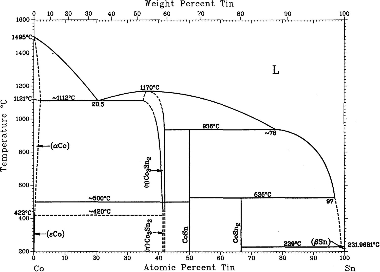
Experimental
The Co-20 at.-% Sn, Co-24 at.-% Sn and Co-30 at.-% Sn alloys used in the present work were prepared with high purity Co (99.99 wt-%) and Sn (99.999 wt-%) in a fused silica crucible by induction furnace. The alloy was remelted in new silica crucibles into cylindrical ingots of 3.8 mm diameter and placed in the alumina crucibles of 4 mm in inner diameter, the directional solidification experiments were performed under an Ar atmosphere in a Bridgman furnace with liquid metal cooling (LMC) tank. The coolant was a Ga–In–Sn liquid alloy, and the temperature gradient ahead of the solid/liquid interface was set to 300 K/cm by adjusting the position of the cooling tank. After being heated up to 1350 °C and held for 30 min, the samples were pulled downward with the set velocities (1–100 µm/s). After 40-mm steady-state growth, the samples were rapidly quenched into the Ga–In–Sn liquid alloy reservoir to retain the solid/liquid interface morphologies. The directionally solidified samples were cut along the longitudinal and transverse sections by wire-electrode cutting. The locations of transverse sections were 5 mm below the quenched solid/liquid interface where the directional solidification had got into a steady state. The specimens were etched with a solution of 5 g copper sulphate, 50 ml hydrochloric acid, and 50 ml water, after being ground and polished. The microstructures were observed by JSM7600F field emission gun scanning electron microscope (SEM) and a Leica optical microscope (OM). The tip splitting frequency (f) was obtained by measuring the distance (h) along the z-axis of two adjacent splitting points on the same branch and dividing it by the growth velocity [13]. The spacing of two tips (λ) was calculated by measuring two adjacent tips as shown in Figure 6(a).
Results and discussion
Quenched solid/liquid interface morphology
Figure 2 shows the morphology of the solid/liquid interface in a longitudinal section and transverse microstructure in directionally solidified Co-20 at.-% Sn hypoeutectic alloy. As shown in Figure 2(a), the solid/liquid interface is planar at the small withdrawal velocity V = 0.5 µm/s, and the transverse microstructure is lamellar eutectic of α-Co/β-Co3Sn2 (Figure 2(b)). At the withdrawal velocity of 10 µm/s (Figure 2(c)), primary α-Co dendrite appeared and grows ahead of the eutectic solidification interface, the sections of dendritic main trunks located at the centre of the colonies in transverse microstructure (Figure 2(d)). As the V increased to 100 µm/s, the primary α-Co dendrite grows into a developed dendritic pattern (Figure 2(e)), and their sizes were decreased with increasing growth velocity. The enlarged view of coupled eutectic growth interface in the red rectangle was shown in the upper right corner of Figure 2(e). As for the quenched interface, it is shown that the leading distance of the primary phase to the coupled eutectic in Figure 2(e) was larger than that in Figure 2(c).
The quenched solid/liquid interface in longitudinal section (a, c and e) and transverse microstructure (b, d and f) in directionally solidified Co-20 at.-% Sn hypoeutectic alloy at G = 300 K/cm and different withdrawal velocities: (a, b) V = 0.5 µm/s, (c, d) 10 µm/s, (e, f) 100 µm/s. The upper right corner of Figure 2(e) is the larger magnification of the corresponding microstructure in the red rectangle.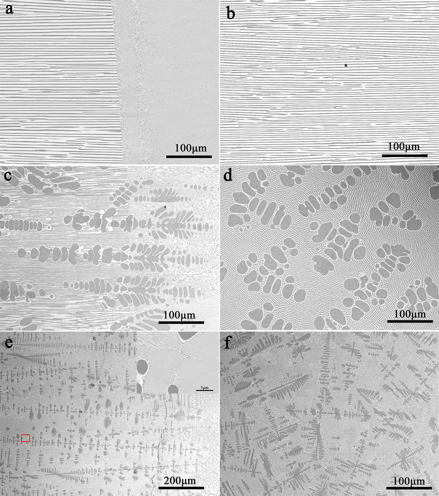
Figure 3 shows the quenched solid/liquid interface in the directional solidification of Co-24 at.-% Sn eutectic alloy at various withdrawal velocities. At the small withdrawal velocity of 1 µm/s (Figure 3(a)), the solid/liquid interface is planar of α-Co/β-Co3Sn2 lamellar eutectic. The solidification interface is destabilised at the withdrawal velocity of 40 µm/s (Figure 3(b)) and transit to cellular at the V of 100 µm/s (Figure 3(c)).
The quenched solid/liquid interface in directionally solidified Co-24 at.-% Sn eutectic alloy at G = 300 K/cm and different withdrawal velocities: (a) V = 1 µm/s, (b) 40 µm/s, and (c) 100 µm/s.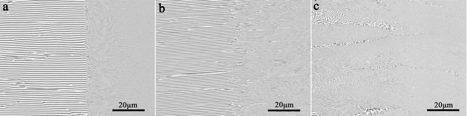
Figure 4 shows the quenched solid/liquid interface in the directional solidification of Co-30 at.-% Sn hypereutectic alloy at various withdrawal velocities. As can be seen in Figure 4(a), the solid/liquid interface is planar at the withdrawal velocity V = 1 µm/s, and the microstructure is composed of α-Co/β-Co3Sn2 lamellar eutectic. At the withdrawal velocity of 2 µm/s (Figure 4(b)), primary phase β-Co3Sn2 appeared and grows ahead of the eutectic solidification interface. It implies that the interface growth temperature of the primary β-Co3Sn2 exceeds that of the coupled eutectic, as would be expected from the phase diagram (Figure 1). As the V increased to 5 µm/s, the primary β-Co3Sn2 phase grows into a developed dendritic pattern (Figure 4(c)). The enlarged view of coupled eutectic growth interface in red rectangle (Figure 4(c)) was shown in Figure 4(d). As for the quenched interface, it is shown that the leading distance of the primary phase to the coupled eutectic in Figure 4(c) was larger than that in Figure 4(b). When V was increased to 10 µm/s, the morphology of the primary β-Co3Sn2 phase was transited to seaweed pattern (Figure 4(e)), which grows through continuous tip splitting and exhibits no obvious orientation preference in the growth direction and no main trunks in the microstructure. Further, as increasing V to 40µm/s and 100 µm/s, the seaweed primary phase is refined while its interface pattern did not change dramatically (Figure 4(g)). But the leading distance of the primary phase to the coupled eutectic gradually increased with the increase of withdrawal velocity.
The quenched solid/liquid interface in directionally solidified Co-30 at.-% Sn hypereutectic alloy at G = 300 K/cm and different withdrawal velocities: (a) V = 1 µm/s, (b) 2 µm/s, (c), (d) 5 µm/s, (e, f) 10 µm/s (g, h) 40 µm/s, (i, j) 100 µm/s. (d, f, h, j) are the larger magnification of the corresponding microstructure in the red rectangle on the left.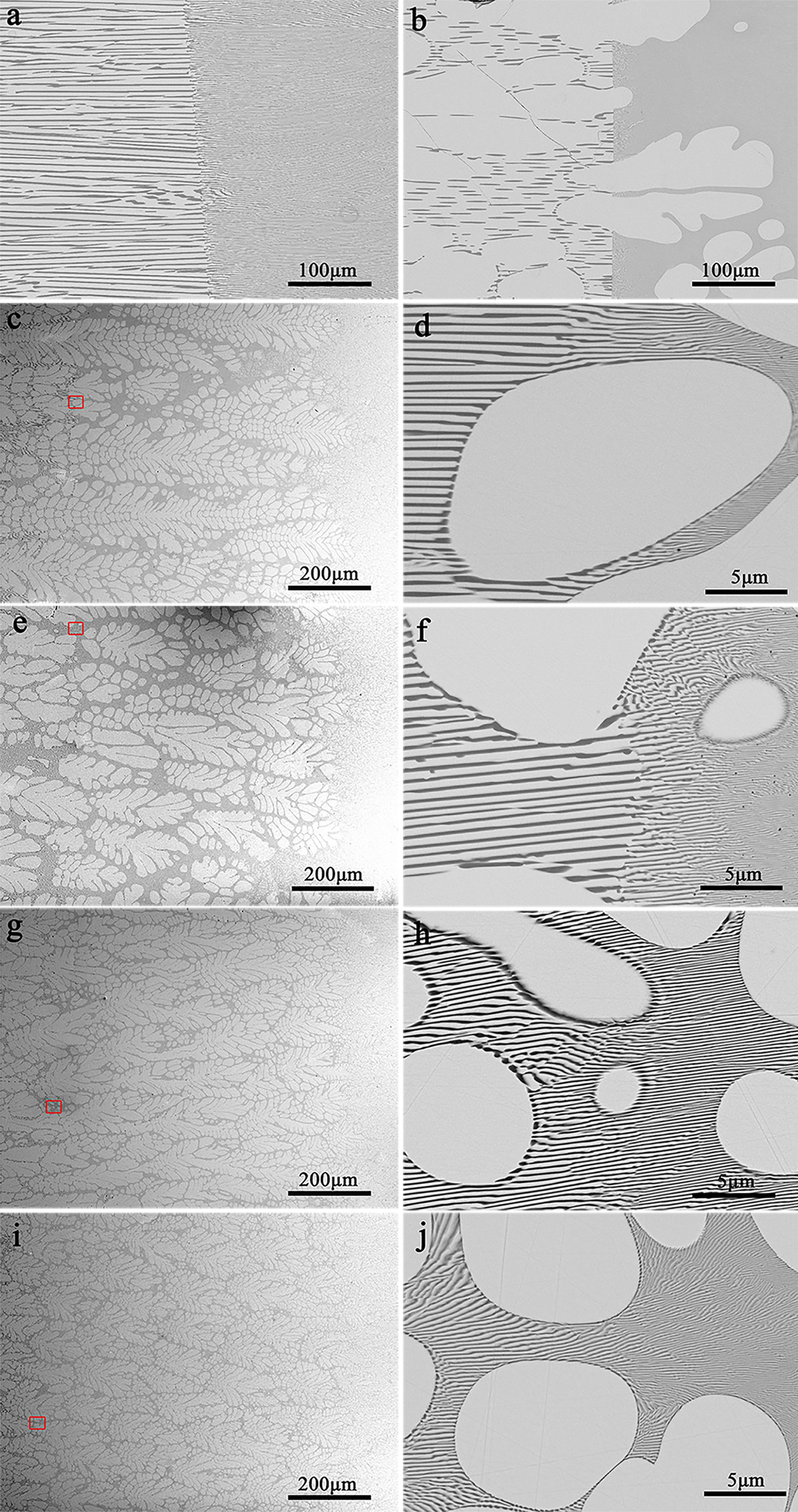
Figure 5 shows the longitudinal and the corresponding transverse microstructures directionally solidified at the withdrawal velocity of 5 and 20 µm/s. As shown in Figure 5(a, b), the primary β-Co3Sn2 phase grows with dendritic morphology, and the dendritic main trunks grows into the direction of temperature gradient (Figure 5(a)), in transverse microstructures the sections of dendritic main trunks located at the centre of the colonies, and the sections of side branches located at the periphery of them (Figure 5(b)). In the case of seaweed growth, the crystal exhibits no obvious orientation preference in growth direction (Figure 5(c)), what's more, it is difficult to identify a central grain in the seaweed growth induced colony in transverse microstructures (Figure 5(d)).
SEM micrographs of the longitudinal (a and c) and transverse (b and d) microstructures of Co-30 at.-% Sn hypereutectic alloy directionally solidified at G = 300 K/cm: (a, b) V = 5 µm/s, (c, d), 20 µm/s.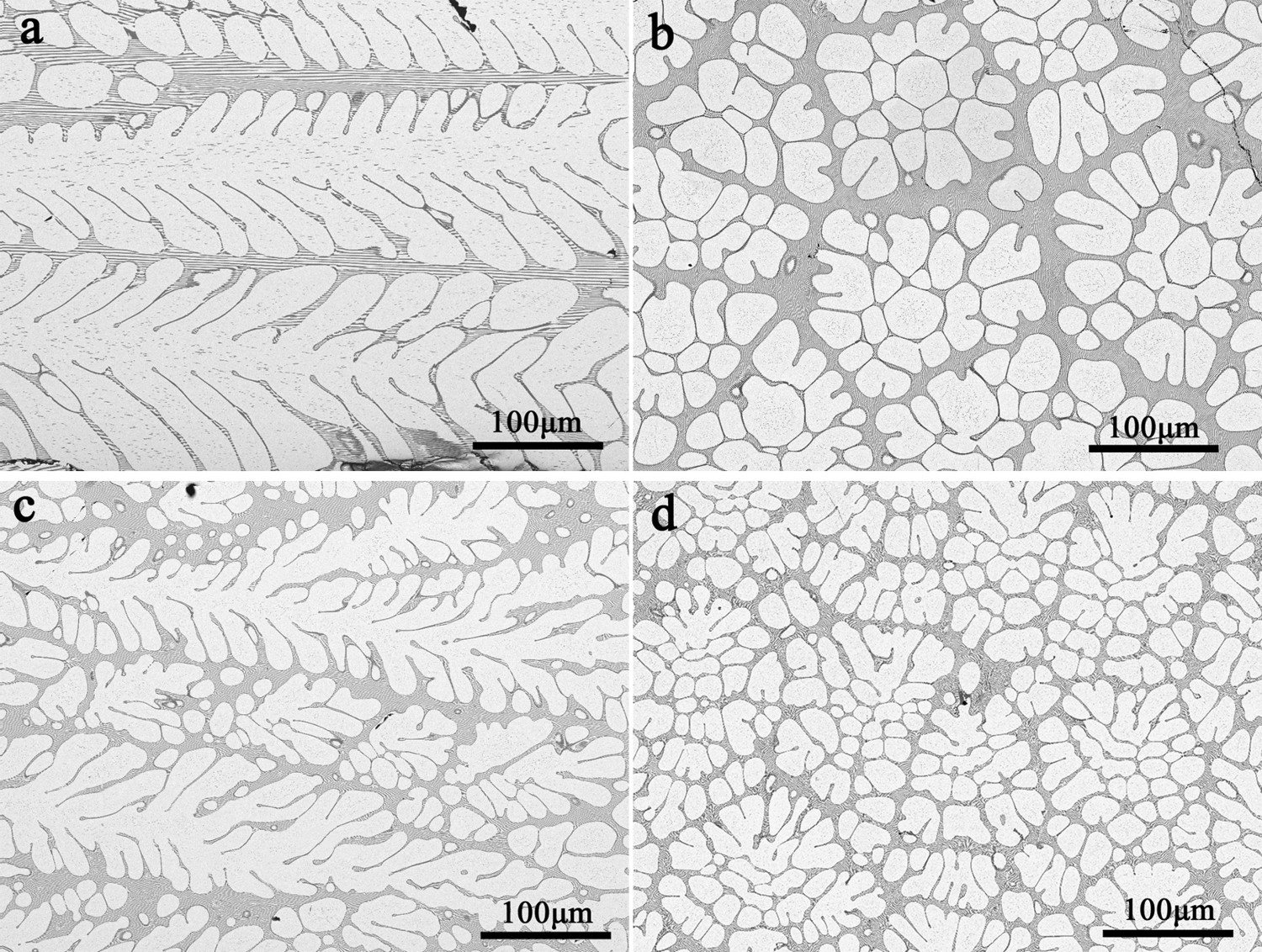
Characteristic parameters of seaweed
When the crystal grows with dendritic morphology, the tip is stable and the side branches appear at a distance behind it, which has a constant tip radius and growth direction. The resultant structure consists of a straight trunk with secondary and tertiary dendrite arms branched from it. Generally, the dendrite is characterised by structural parameters such as primary dendrite spacing, secondary and tertiary dendrite arm spacing. In contrast, the seaweed grows with weaker interfacial energy anisotropy, the tip in seaweed growth is unstable and it will undergo continuous tip splitting. In this case, both of the new branches grow along the directions deviating from the mother one. It is difficult to distinguish between the trunk and side branches. Therefore, the splitting frequency (f) and the spacing of two tips (λ) are two important characteristic parameters of the seaweed growth pattern. Figure 6(a) shows the seaweed growth at the withdrawal velocity of 20 µm/s. For comparison, the experimental results by Utter et al [16] and Wang et al [13] were presented in Figure 6(b, c) also. It can be clearly seen that the value of λ decreases with the increases of V. The relationship between the spacing of two tips and growth velocity follows the power law:
(a) Illustration of measuring the spacing of two tips λ and the splitting distance h, (b) the spacing of two tips λ and (c) tip splitting frequency f of β-Co3Sn2 seaweeds versus growth velocity in the directional solidification of Co-30 at.-% Sn hypereutectic alloy.
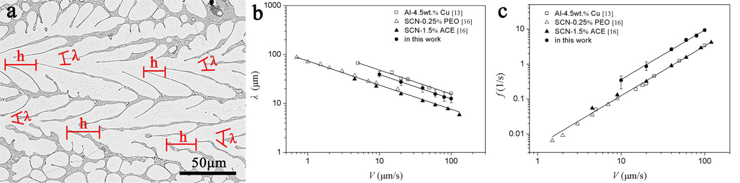
The plot of the log λ versus log V is essentially linear for both the results in this work and previous work, and the value of the exponent e is equal to −0.5. The difference of prefixing coefficient of the fitting function is dependent on the specific material properties, based on the M-S [29] linear analysis of the instability of a planar front.
The tip splitting frequency f as a function of growth velocity follows the power law  (Figure 6(c)). Accordingly, the interface instability wavelength is related to growth velocity as
  [29]. From dimensional analysis, one can see that the tip splitting frequency results from the growth velocity divided by the interface instability wavelength. That is,
  appears to be satisfied. So, the experimental results are qualitatively consistent with the theoretical value 1.5. Utter et al. [16] obtained that the exponent is 1.56 and 1.40 in directionally solidified SCN-0.25% PEO and SCN-1.5% ACE alloys, respectively. It seems that all these seaweeds follow the same law for their tip splitting.
Microstructural morphologies of Co–Sn alloys
Figure 7 shows the microstructural morphologies of Co-(20-32) at.-% Sn alloys directionally solidified at a temperature gradient of 300 K/cm and different withdrawal velocities. It can be seen that the alloy with eutectic composition can obtain complete regular lamellar eutectic structure at all withdrawal velocities, while the alloy with composition between 22–30 at.-% Sn can obtain a complete eutectic structure when the withdrawal velocities are relatively small. However, with the increase of withdrawal velocities, the composition range of complete regular eutectic is narrowed, which makes the shape of the coupled eutectic region is ‘inverted cone’, and the solidification structure outside it is α-Co primary phase + eutectic (hypoeutectic composition) or β-Co3Sn2 primary phase + eutectic (hypereutectic composition).
Microstructural morphologies of Co–Sn alloys directionally solidified at a temperature gradient of 300 K/cm and different withdrawal velocities.
There appears the competitive growth between primary α-Co or β-Co3Sn2 phase and the α-Co/β-Co3Sn2 eutectic in the directional solidification of Co-20 at.-% Sn hypoeutectic or Co-30 at.-% Sn hypereutectic alloy. As the constitutional undercooling is small, an entirely coupled eutectics will be observed at a small withdrawal velocity. With the increase of withdrawal velocity, the solidification interface temperature will be located out of the coupled zone, and primary α-Co or β-Co3Sn2 dendrites grow ahead of the eutectic phase. What's more, the interface temperature difference between primary phases and the coupled eutectic increases with increasing the withdrawal velocity. So, the leading distance of the primary phase to the coupled eutectic is larger at the higher withdrawal velocity. The effective dynamic anisotropy in a combination of interfacial energy anisotropy with kinetic anisotropy can be represented as [30]:
 and (0001) of hexagonal β-Co3Sn2 is only 0.204 [31], less than 0.252 for Al and 0.376 for Zn whose solids grow dendritically in their alloy melts, respectively. So β-Co3Sn2 owns relatively weak interfacial energy anisotropy, which promote the transition from dendritic to seaweed growth at large withdrawal velocity, like, 100 µm/s.
Conclusions
The evolution of the solid/liquid interface morphology in the directional solidification of Co-20 at.-% Sn hypoeutectic, Co-24 at.-% Sn eutectic and Co-30 at.-% Sn hypereutectic alloys have been investigated at a temperature gradient of 300 K/cm. It can be concluded that:
The solid/liquid interface morphology of Co-20 at.-% Sn hypoeutectic alloy transformed from a planar interface at small withdrawal velocity to dendritic α-Co phase plus eutectic at large withdrawal velocity, and the planar solidification interface of Co-24 at.-% Sn eutectic alloy destabilised to cellular with the increase of withdrawal velocity. As for Co-30 at.-% Sn hypereutectic alloys, the quenched solid/liquid interface transits from planar lamellar eutectic to primary β-Co3Sn2 dendrites plus eutectic and then to primary β-Co3Sn2 seaweeds plus eutectic with increasing withdrawal velocity. At a critical velocity, the interface growth temperature of the primary β-Co3Sn2 exceeds that of the coupled eutectic, which would grow ahead of the couple eutectic, and the leading distance is increased with withdrawal velocity. The spacing of the two tips of β-Co3Sn2 seaweed in the alloys followed a power law,
 , and the tip splitting frequency versus growth velocity as the function of
  .
.
Footnotes
Disclosure statement
No potential conflict of interest was reported by the author(s).