
Abstract
To enhance the mechanical properties of cast Al–Si–Cu alloys (ADC12), 0.3% of carbon nanotubes (CNTs) was added. The cast ADC12–0.3%CNT samples were synthesised via heated mould continuous casting for the creation of fine grains, and the artificial aging process was conducted at 173°C for 13 h to obtain precipitation hardening. The reinforcement and refinement of eutectic Si and precipitates (Al2Cu and Mg2Si) were achieved by adding CNTs, which leads to a high tensile strength of about 450 MPa and a relatively high ductility of about 10%. The obtained tensile strength and 0.2% proof stress are more than twice as high as those of the conventional cast ADC12 alloy. The refinement of the microstructures could be due to the interruption of their growth caused by the CNTs.
Introduction
Owing to the issues caused by global warming, aluminium alloys have received special attention. In particular, the use of aluminium alloys for automotive parts in place of steel and iron has increased in recent years. These automotive parts are typically fabricated using various processes, such as forging, stamping, and casting. The casting process is extensively employed as it is efficient and can be used for the creation of complex shapes. However, cast aluminium alloys are not always adequate as engineering alloys as they lack mechanical strength. To improve the mechanical properties of cast aluminium alloys, various casting technologies have been proposed, such as squeezed casting [1], melt drag twin-roll casting [2], semisolid rheo-casting [3], and heated mould continuous casting (HMC) [4]. Commercial cast aluminium alloys (ADC12) synthetised via the HMC process exhibit good tensile strength properties; specifically, which is more than 1.5 times higher than that of ADC12 alloys obtained via the conventional die casting process [5]. Furthermore, artificial aging has been carried out to obtain high-strength HMC-ADC12 alloys (382 MPa [6]); during this process, severe CuAl2 precipitation occurs. However, the mechanical strength of these alloys is still lower than those of steel and iron.
Recently, there has been an increasing interest in carbon materials because of their excellent material properties. In particular, carbon nanotubes (CNTs) have been proposed as a composite material for aluminium [7] and wrought Al alloys [8]. It was reported that the tensile strength of Al–CNT alloys increases through the combination of spark plasma sintering and hot-extrusion processes without compromising the elongation ability [9]. Al–CNT alloys were synthesised by cold spraying a blended powder. A high elastic modulus was obtained due to the reinforcement effect of the CNTs and the locally high number of CNTs; the modulus value was obtained via nanoindentation measurements [10]. Furthermore, CNT-reinforced aluminium alloys (6000 series) were synthesised via the semisolid powder process. The effect of different processing temperatures (namely 600, 620, and 640°C) on the material properties was investigated; the highest hardness was achieved at the processing temperature of 620°C [11]. The tensile and yield strengths of Al alloys were improved with the addition of 0.2 wt-% CNTs. These enhancements confirm the predicted values from the multiple strengthening mechanisms, such as the generation of dislocations and the Orowan looping system [12]. The abovementioned results reveal that CNTs are suitable to obtain high-strength Al alloys. Although the effect of CNTs on the mechanical properties of Al alloys has been investigated for wrought Al alloys, no clear results have yet been reported on the effect of CNTs on the mechanical properties of cast Al alloys, especially the conventional ADC12 alloy. Thus, in this work, an attempt was made to obtain high-strength cast ADC12 alloys through the addition of CNTs. The ADC12–CNT cast samples were fabricated using the unidirectional solidification process, and artificial aging was conducted to obtain excellent mechanical properties.
Experimental procedures
Materials and sample preparation
The commercial ADC12 alloy was used in this work; this alloy has been employed in the fabrication of many automotive parts. The chemical composition of this alloy is Al–10.6Si–2.5Cu–0.3Mg–1.1Fe in wt-%. To examine the effect of the addition of CNTs on the mechanical properties of the ADC12 alloy, CNT powders (0.3 wt-%) were used in the cast ADC12 alloy. In this case, conventional multi-walled CNTs with 5–35 µm in length and 20–40 nm in diameter were selected as the first approach. Figure 1 shows photograph and SEM image of CNTs. It should be noted that, in this approach, 0.3%-CNT was added in the cast ADC12 alloy due to the high strength which obtained in our pre-experimental work, where the material properties of ADC12–CNT (0.1–1.0 wt-%) are investigated.
Photographs of the multi-walled carbon nanotube (CNT).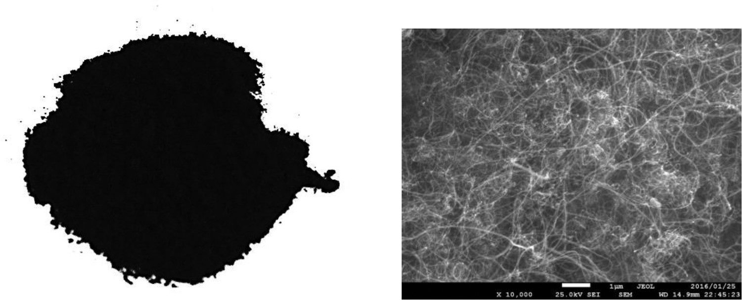
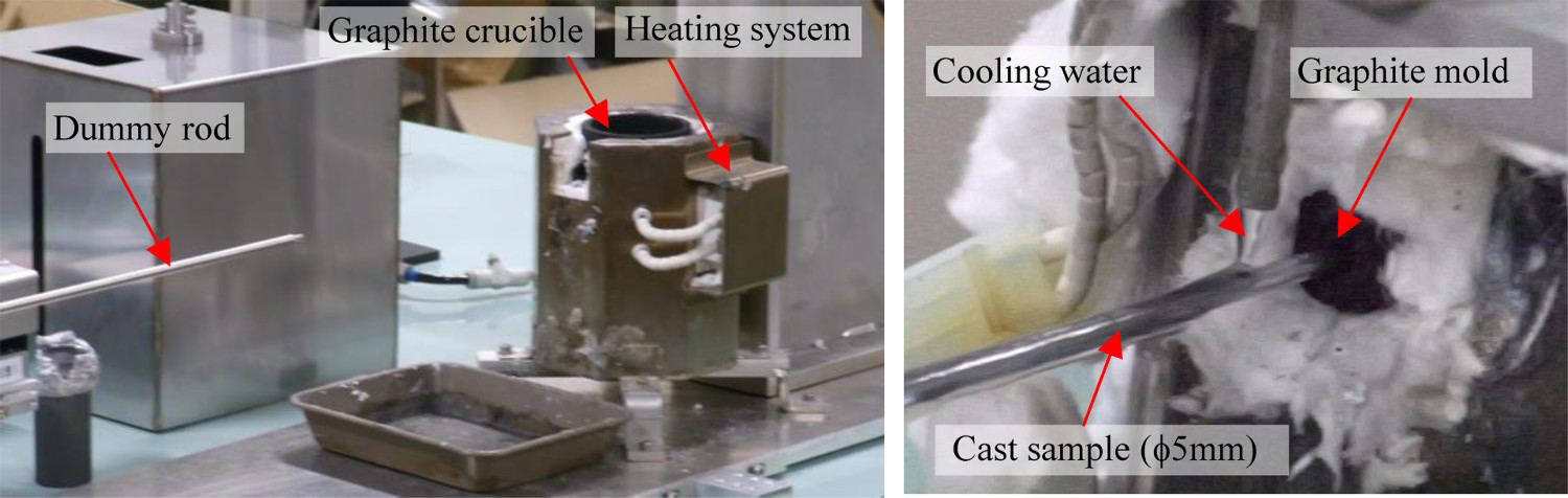
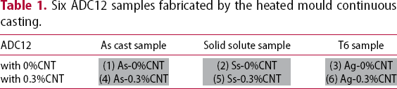
As it is technically difficulty to mix the CNT powders to the Al alloy, an ADC12–CNT ingot was fabricated in advance through the following process: CNT powders (0.3 wt-% CNTs) were placed into small holes with dimensions of ϕ2 × 5 mm2. These holes were made in a small ADC12 block (with dimensions of 30 × 30 × 7 mm3), which was covered by a 3-mm-thick ADC12 plate before being melt in an electric furnace. The melt ADC12 with the 0.3 wt-% CNTs was then injected into a rotating mould (the cavity has dimensions of 100 × 50 × 5 mm3) at 400 rev min–1 to create an ADC12–CNT plate. Figure 2 shows the rotation casting device and the CNTs. This casting device was originally designed in such a way as to be able to change the mould temperature (25–400°C) and the rotation speed (0–400 rev min–1). The ADC12–CNT ingot fabricated via rotation casting was remelted in the crucible at a temperature of 635°C. Subsequently, the cast samples were synthesised via the HMC process. The HMC process was selected in this work to obtain fine grains with a lower number of cast defects [13]. Figure 3 displays the HMC device designed originally. In this approach, a horizontal HMC arrangement was employed, consisting of a heating system, a graphite mould, a graphite crucible, a cooling device, and a dummy rod for withdrawal of the cast sample [14]. The casting speed was set to be approximately 1.9 mm s−1 as high-quality cast samples can be produced at this speed [15]. The molten metal was fed into the graphite mould continuously using a dummy rod made of stainless steel. The head of the mould was machined with ϕ 5 mm. The mould was heated up to a target temperature of 625°C, which is the temperature just above the liquidus of the cast ADC12. The cast sample was cooled through water droplets falling from the top of the cast sample, where the amount of cooling water was approximately 150 ml min−1. With this HMC process, round rod samples of ADC12–CNT with dimensions of ϕ5 mm × 1 m were produced, i.e. as-cast sample (As). Some of these As-ADC12–CNT samples were heat treated to enhance their mechanical properties. Two heat treatment processes were used: the solid solution at 500°C for 1 h (Ss) and T6 treatment (Ss + artificial aging at 173°C for 13 h (Ag)) [6]. Namely, six samples were prepared in the present work, which is summarised in Table 1.
(a) Rotation casting device used to fabricate the ADC12–CNT ingot and (b) the ADC12–CNT ingot. Photographs of the heated mould continuous casting (HMC) device. Six ADC12 samples fabricated by the heated mould continuous casting.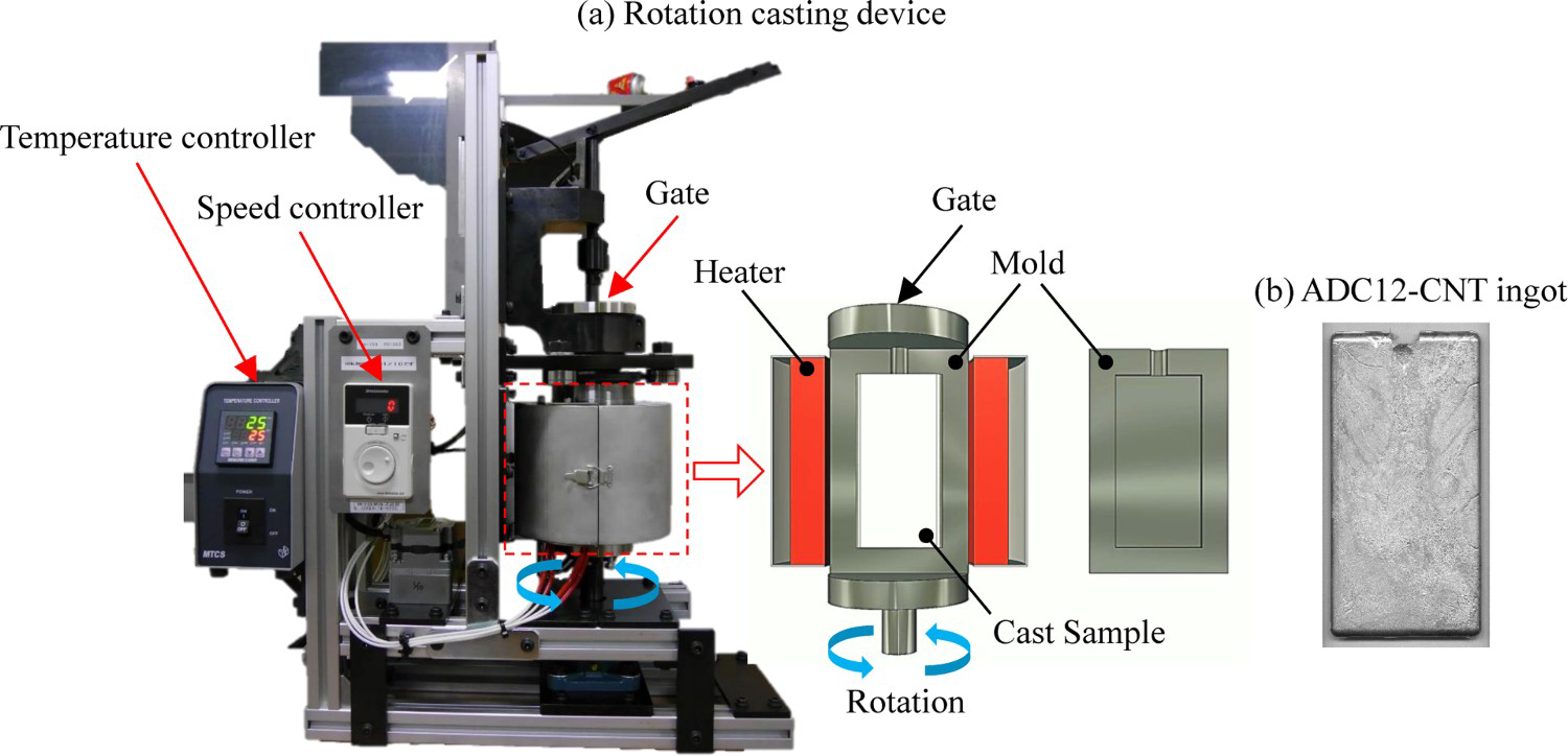
Mechanical property characterisation
The influence of the microstructural characteristics on the mechanical properties was examined at 25°C via hardness and tensile tests. The hardness tests were conducted using a Vickers hardness tester by applying a force of 98 N to the samples for 15 s. The tensile tests were carried out using a screw-driven universal testing machine with a 50-kN capacity. In this case, dumbbell-shaped round specimens with dimensions of ϕ2 × 4 mm2 were used. Tensile loading was applied at a rate of 1 mm min−1 up to the fracture point. The tensile properties were evaluated via the stress–strain relationship, which was recirded using a data acquisition system in conjunction with a computer through a load cell and a strain gauge.
Microstructural observations
The microstructural characteristics of the ADC12–CNT alloys were examined via electron backscatter diffraction (EBSD) analysis. EBSD measurements were conducted using a high-resolution scanning electron microscopy (SEM) system (JSM-7000F, JEOL) with an acceleration voltage of 15 kV, a beam current of 12 nA, and a step size of 0.1 µm. For this analysis, the sample surface was polished to a mirror status using 1-µm alumina particles.
To examine the precipitation characteristics of the ADC12–CNT alloy after artificial aging, microstructural observations were also performed using a scanning transmission electron microscopy (STEM, Talos F200X) system with an accelerating voltage of 200 kV. The STEM samples were prepared via mechanical thinning followed by etching in a solution containing 1% of nitric acid and 99% of methanol; a thickness of approximately 100 nm was obtained. Before the STEM observations, the sample surface was coated by carbon.
Results and discussion
Microstructural characteristics
Figure 4(a) shows the optical images of the HMC-ADC12 samples with and without the CNTs (i.e. 0.3wt-% CNT and 0wt-% CNT); these samples underwent the As, Ss, and Ag processes. Note that the microstructure of the HMC samples was observed in the cross section of the cast samples, which is parallel to the casting direction. As can be seen, the As-samples consist of a dendrite structure of the α-Al phase and an Al–Si binary eutectic growth in the form of a complex structure between the α-Al grains. Interestingly, the microstructural formation is altered upon adding the CNTs, e.g. a fine eutectic Si phase is created in the As-sample with 0.3% CNTs (As-0.3% CNT), as indicated by the blue dashed circles. With the Ss and Ag processes, the microstructural formation is apparently altered, and eutectic Si is formed with a spherical shape. Such different eutectic Si was clarified in STEM images shown in Figure 4(b). Morphology of eutectic Si in As-0.3%CNT consists of complicated formation, while the round shape of eutectic Si is observed in Ag-0.3%CNT.
(a) Optical micrographs of the cast ADC12 with and without CNT; (b) STEM images of the As- and Ag-0.3%CNT.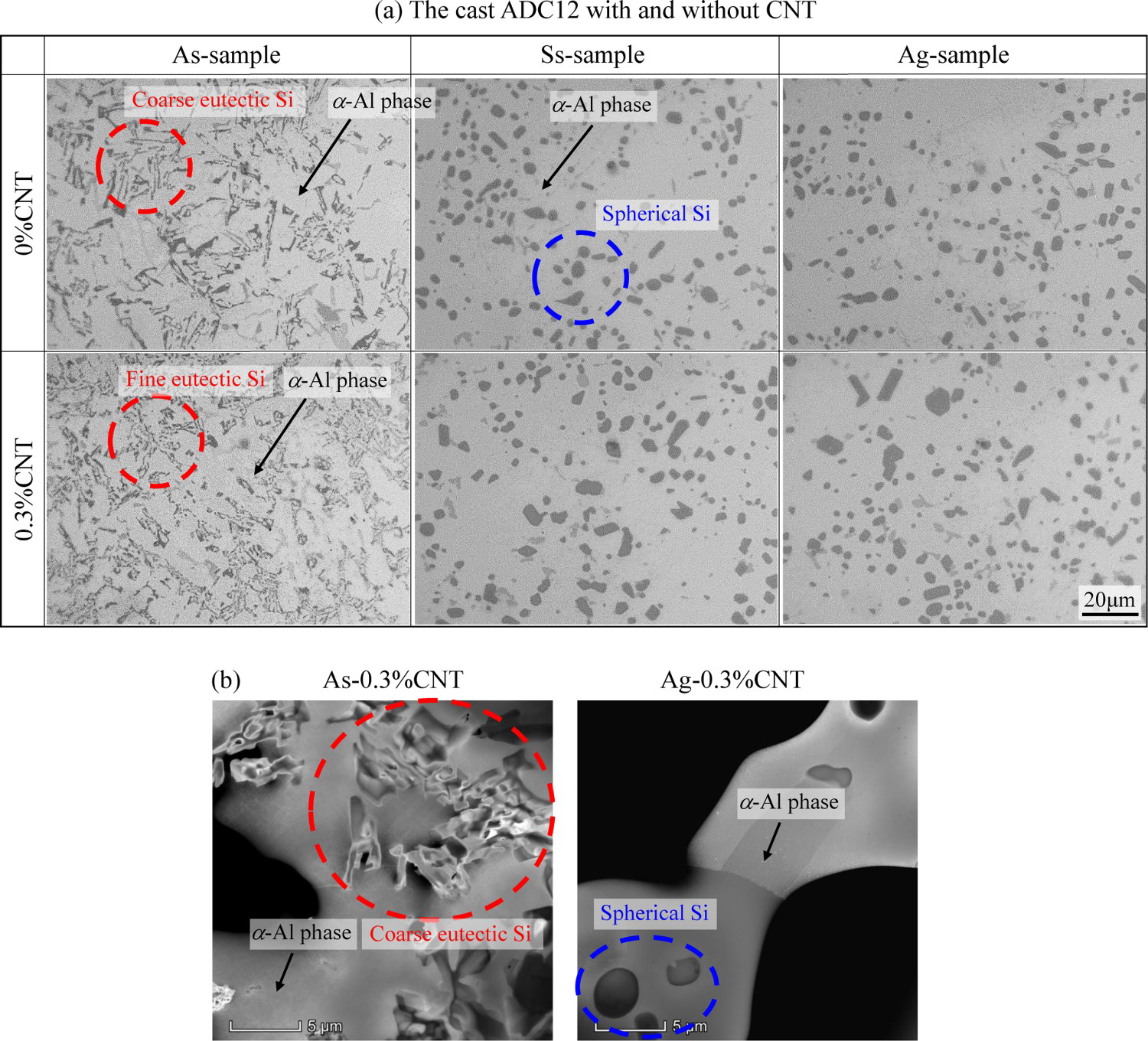
To understand the reason for the creation of a fine eutectic structure in the As-0.3%CNT sample, the microstructural characteristics of the ADC12 alloy were examined after carbon addition. To this aim, a carbon rod with a diameter of 0.7 mm was placed into the liquid ADC12 alloy for 1 h before its solidification. Figure 5 displays the SEM image of the microstructure of the ADC12 alloy around the carbon rod and the result of the EDS analysis. It is clear from the SEM image that the nature of the eutectic Si phase depends on the observation area: e.g. a fine eutectic Si phase is created in the sample around the carbon rod, as indicated by the dashed blue line. Moreover, the EDS analysis reveals that carbon is present in the aluminium matrix, although at a low level, as indicated by the dashed yellow circles. This indicates that a change in the microstructure has occurred; e.g. carbon may hinder the growth of eutectic Si [16]. However, further studies will be required to verify this.
Microstructure of the ADC12 alloy around the carbon rod and the result of EDS analysis.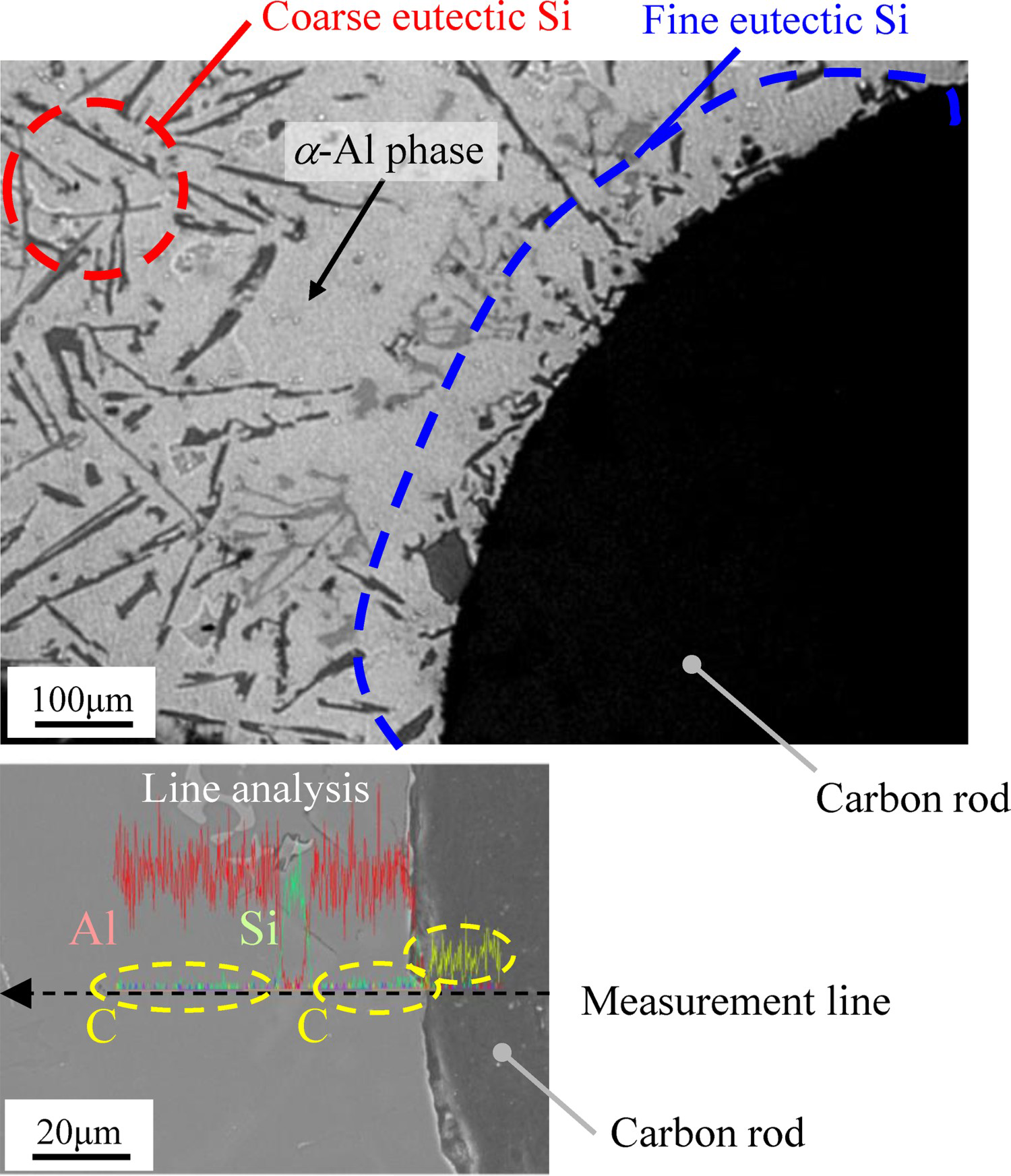
The microstructural characteristics of the HMC-ADC12 samples with and without CNTs after the aging process were examined via EBSD. Figure 6(a) depicts the inverse pole figure (IPF) and kernel average misorientation (KAM) map of the HMC samples. Figure 6(b) shows the mean KAM values in the α-Al phase for both samples. The red areas in the IPF maps are related to [100]Al, i.e. they correspond to the α-Al phase. On the other hand, the eutectic Si phase is formed with spherical shape with different crystal orientations as indicated in Figure 6. Although the microstructural characteristics in the IPF maps of the two samples are similar, their KAM values are different. The mean KAM value of the Ag-0.3%CNT sample is about 0.67°, which is about 1.5 times higher than that of the Ag-0%CNT sample. Moreover, increment of high internal strain is apparently detected after the Ag process. From those results, it can be inferred that the Ag-0.3%CNT sample exhibits severe precipitate strengthening.
Inverse Pole Figure and Kernel Average Misorientation maps of the Ag-0%CNT and Ag-0.3%CNT samples and the mean KAM value in the α-Al phase.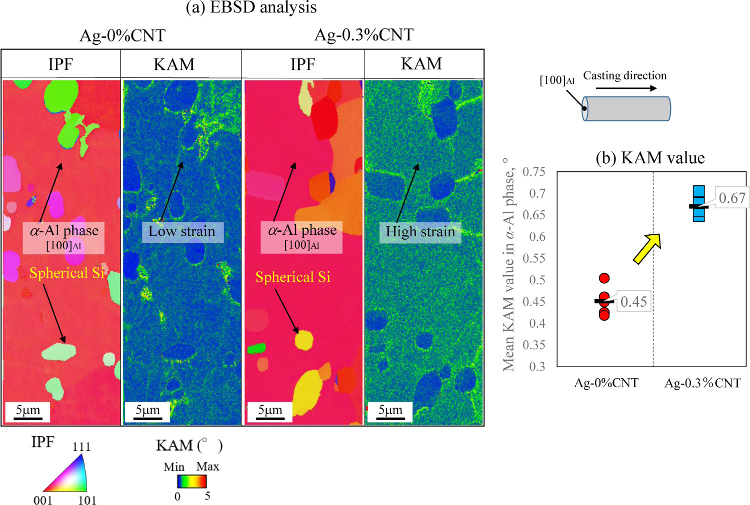
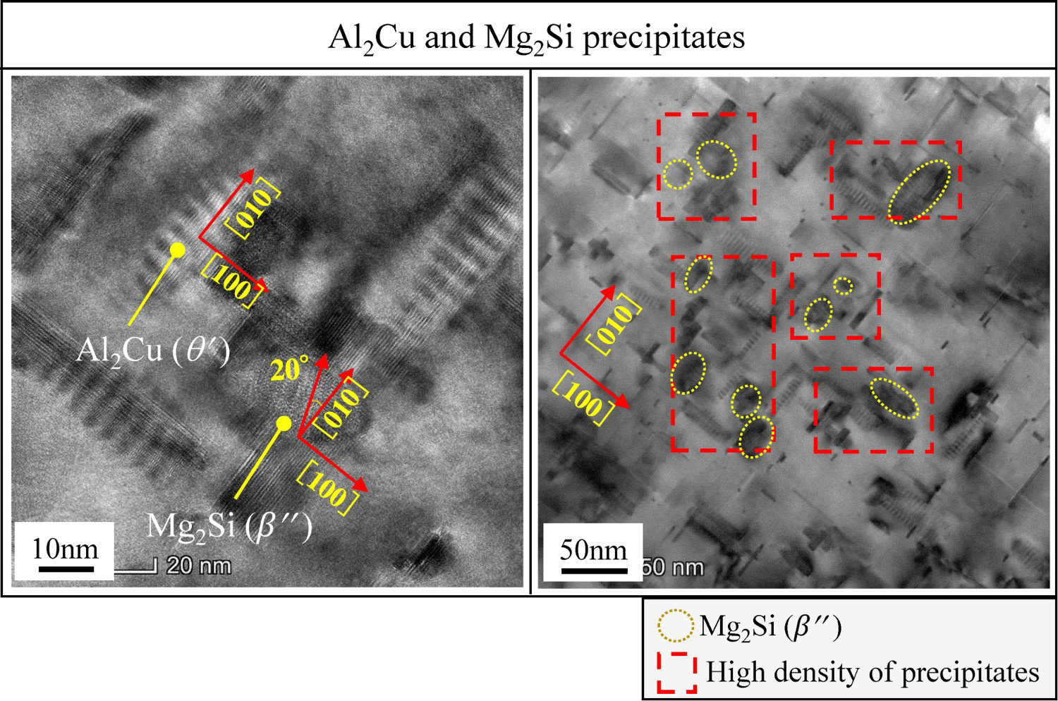
To understand the reason for the high internal strain in the Ag-0.3%CNT sample, STEM observations were carried out. Figure 7(a) shows the STEM images of the cast samples with and without CNTs after the aging process [6]. Figure 7(b) shows the results of the TEM-EDX analysis conducted on the α-Al phase of the Ag-treated samples. It is clear from this analysis that the θ′(Al2Cu) metastable phase and the pre-β″ metastable phase (Mg2Si) can be obtained in the α-Al matrix. Moreover, in the Ag-0.3%CNT sample, a fine precipitation is detected with a high density in the α-Al matrix. Figure 8 shows the STEM images of the Ag-0.3%CNT sample with high magnifications. It is clear that the θ′(Al2Cu) metastable phase is formed along the [100]Al direction in the α-Al matrix, where the average size of the platelike Al2Cu is 10 × 3 nm2. The [100]Al direction of the θ′ phase is related to the casting direction, which is in good agreement with the result of the EBSD analysis shown in Figure 6. The fact that the [100]Al direction is parallel to the casting direction of HMC is attributed to the stress direction arising from the solidification of the ADC12 alloy (shrinkage stress). It has been reported [17] that θ′ precipitates are preferentially oriented parallel to an externally applied tensile stress; furthermore, the nucleation of precipitates is influenced by the applied stress. In this case, precipitation endows the HMC sample with high strength; this process is known as precipitation hardening. On the other hand, coarsening of the θ′ (Al2Cu) metastable phase, i.e. 50 × 3 nm2, with a lower density is observed in the Ag-0%CNT sample. Such large θ′ (Al2Cu) phases could weaken the precipitation hardening process of the cast samples. The difference in the precipitation characteristics between the Ag-0.3%CNT and Ag-0%CNT samples is due to the degree of internal strain, as shown in Figure 6(b). From this figure, it can be seen that the higher the KAM value, the finer the precipitates. It is also clear from Figure 8 that the pre-β″ metastable phase (Mg2Si) formed in the α-Al matrix has a different direction compared with that of the θ′ (Al2Cu) phase. Similar precipitates have been reported in a previous study, where 0.23-nm-wide Mg2Si precipitates formed and had a different direction compared with that of other precipitates, e.g. Al3(Sc, Ti) [18]. In addition, a large number of the precipitates, including θ′ (Al2Cu) phase, are observed around β″ metastable phase in the Ag-0.3%CNT sample. This occurrence may be attributed to the addition of CNT; however, further study will be required in the future.
(a) STEM images of the Ag-0%CNT [6] and Ag-0.3%CNT samples and (b) TEM-EDX analysis in the α-Al phases of the Ag-0.3%CNT samples. STEM images of the Ag-0.3%CNT sample showing Al2Cu and Mg2Si precipitates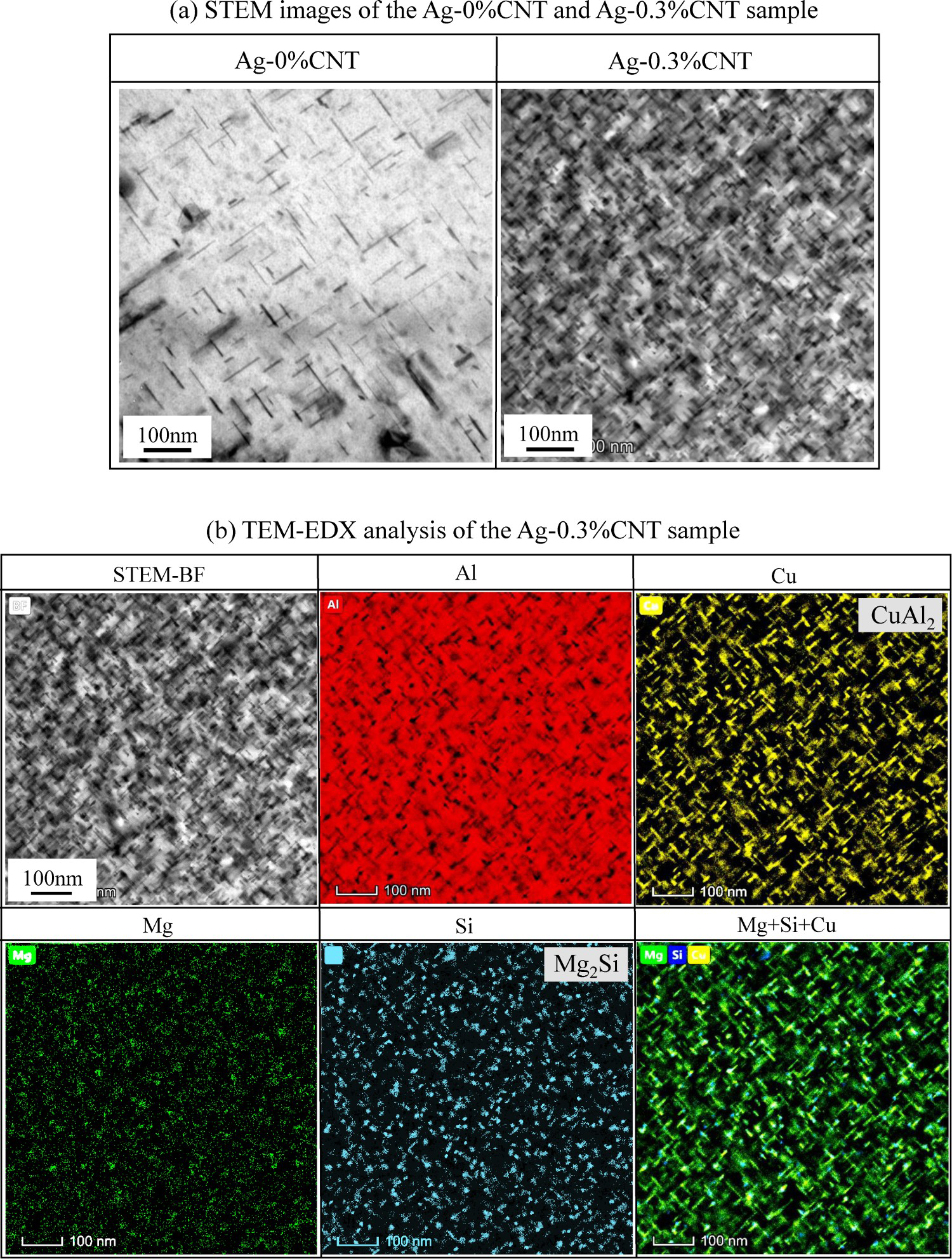
Mechanical properties
Figure 9 shows the results of the Vickers hardness tests for the various samples. The hardness value is higher for the samples that were heat treated via the Ss and Ag processes compared with that of the As-samples. Moreover, the hardness values of the 0.3%CNT samples are overall higher than those of the 0%CNT samples under the same treatment. This change in the hardness value is caused by the different microstructural characteristics, as discussed above. To verify the mechanical properties of the cast samples, tensile tests were carried out.
Vickers hardness of the As-, Ss- and Ag-treated samples.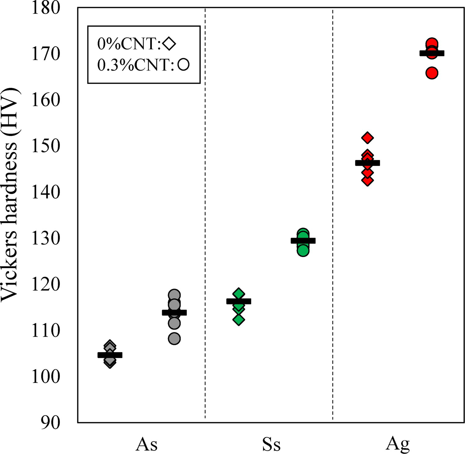
Figure 10(a) shows representative stress–strain (S–S) curves, and the obtained tensile properties, including the ultimate tensile strength, 0.2% proof stress, and fracture strain, are summarised in Figure 10(b). Note that the elastic constants for all samples are almost same level of about 70 GPa. From the S–S curves, the different tensile properties are observed for the different samples. Upon addition of the CNTs, the UTS value increases: σUTS = 390 MPa for the As-0.3%CNT sample and σUTS = 360 MPa for the As-0%CNT sample. This is caused by the reinforcement effect of the CNTs on the Al matrix for the As-0.3%CNT sample. The S–S curves for the 0.3%CNT samples are improved by the heating process. As illustrated in Figure 10, the highest tensile strength and 0.2% proof stress (σUTS and σ0.2) were obtained for the Ag-0.3%CNT sample (σUTS = 450 MPa and σ0.2 = 370 MPa). Furthermore, a relatively high ductility (ϵf) was obtained for the Ag-0.3%CNT sample (ϵf = 10%), although this fracture strain value is about half of that of the Ss-30%CNT sample (ϵf = 18%). Such a high tensile properties of the Ag-0.3%CNT sample would be attributed to the severe precipitations as displayed in STEM images, i.e. precipitation strength. Haghgoo et al. [19] have done excellent works, in which the effect of CNT on the mechanical properties of Al-CNT is examined. They have obtained high tensile strength and high elastic modulus with increasing CNT volume. Moreover, high mechanical strength was detected when CNT is distributed uniformly in the Al matrix. In our pre-experimental work, the high tensile strength was obtained ADC12–0.3%CNT although the tensile strength decreased as 1.0%CNT is added, as described previously. The reduction of the tensile strength can be related to the ununiformly distributed CNT powders.
(a) Tensile stress versus tensile strain curves of the As-, Ss-, and Ag-treated samples and (b) ultimate tensile strength, 0.2% proof stress, and fracture strain values.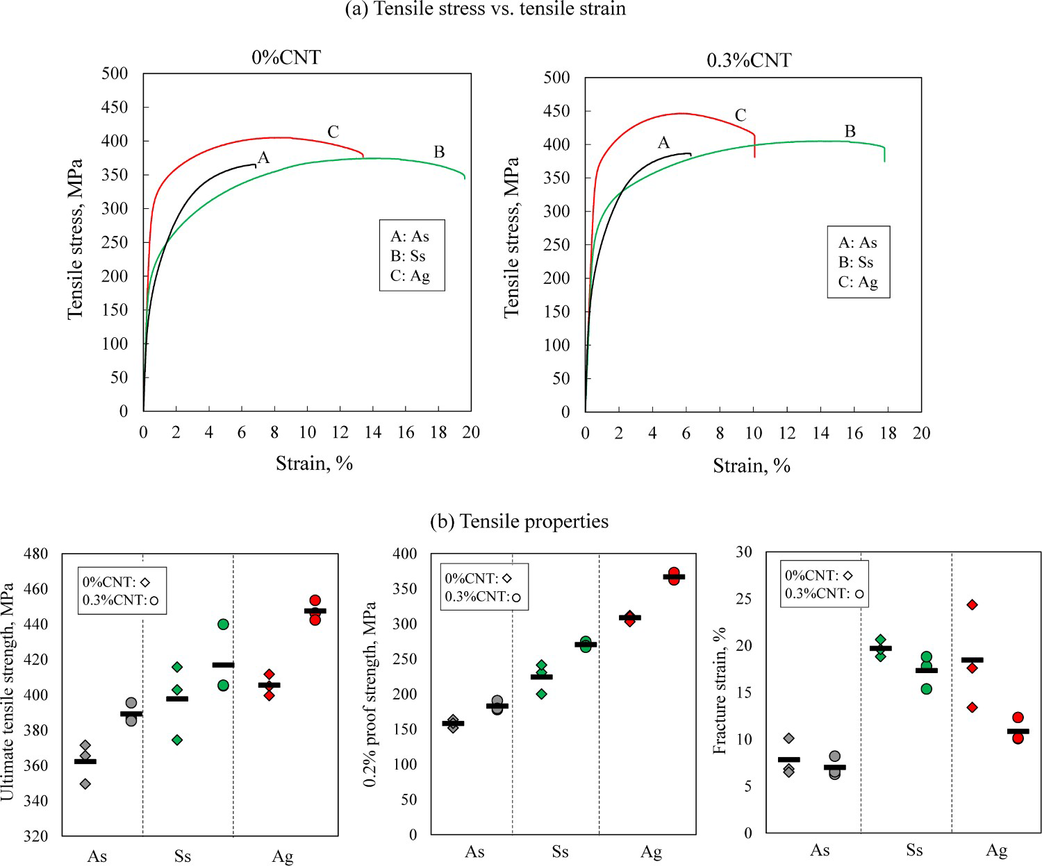
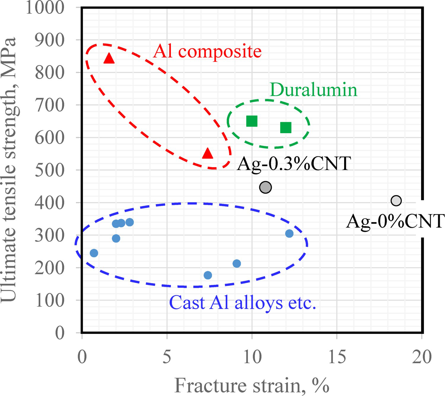
The tensile properties of the 0.3%CNT samples were compared with those of related aluminium alloys reported in previous studies. Figure 11 shows the relationship between the ultimate tensile strength σUTS and the fracture strain ϵf of various engineering materials [20-26], including the Ag-0%CNT and Ag-0.3%CNT samples. From Figure 11, it is seen that our cast samples exhibit a relatively high tensile strength with a high ductility, even though the σUTS values are lower than those of duralumin and the Al components. Indeed, no cast aluminium alloy exhibits a tensile strength of more than 400 MPa. It can thus be concluded that the proposed technique is suitable for obtaining cast ADC12 alloys with excellent mechanical properties.
Conclusions
The microstructure and mechanical properties of the ADC12–CNT alloys were experimentally examined after artificial aging at 173°C for 13 h. The obtained results can be summarised as follows:
High-strength cast ADC12 alloys were obtained upon adding CNTs and after the Ag process. Upon adding 0.3% CNTs, precipitation hardening occurred, and fine precipitates of Al2Cu and Mg2Si with high density were embedded in the α-Al phase. Moreover, a fine eutectic Si phase was obtained upon adding CNTs due to the interruption of the precipitations. Upon adding CNTs (i.e. the As-0.3%CNT sample), the tensile strength was improved possibly due to the reinforcement effect of the CNTs on the Al matrix. A high tensile strength was obtained for the Ag-0.3%CNT sample (σUTS = 450 MPa and σ0.2 = 370 MPa); these values are much higher than those of other cast Al alloys. This high tensile strength is due to the high-density fine precipitates, namely Al2Cu and Mg2Si.
Footnotes
Disclosure statement
No potential conflict of interest was reported by the author(s).