
Abstract
Network carbides, as a deleterious precipitate to the mechanical properties of bearing steel, are difficult to eliminate by traditional heat treatment. Here, an innovative strategy to rapidly dissolve network carbides using electric current pulses to improve the uniformity of the microstructure is proposed. The results show that the diffusion driven by electromigration is significantly enhanced compared to traditional heat treatment due to the high-density current on the network carbide surface. Furthermore, grain boundaries as fast diffusion paths play a key role in accelerating the dissolution of network carbides.
Keywords
Introduction
Bearings are widely used as the critical components with strict requirements in the industry [1]. As the main material for bearing manufacturing, high-carbon bearing steel accounts for more than 80% of the bearing steel production around the world [2]. The higher carbon content (about 1 wt.%) improves the rolling contact fatigue and wear resistance of bearings, thus extending their service life [2,3]. During the cooling process of hot-rolled bars, carbides will precipitate along grain boundaries, causing coarse and continuous carbides, i.e. network carbides [4]. As the source of microcracking and crack expansion pathway during deformation, the network carbides will lead to serious intergranular fracture and thereby deteriorate the mechanical properties [5,6]. Spheroidising annealing treatment is usually applied to the bars after rolling in the industrial production for bearing steels. For the high-carbon bearing steel with a large number of network carbides, extending the annealing process can partially dissolve the network carbides and break the network continuity to a certain level [7].
Owing to the high defect density at grain boundaries, the carbon atoms here have a lower diffusion activation energy [8,9]. The grain boundary diffusion dominates at the lower temperature, which is beneficial to eliminate the network carbides located at the grain boundaries. Nevertheless, reducing temperature is disadvantageous for the system to overcome the thermal barriers of carbide dissolution [10]. Moreover, as the diffusion rate of carbon atoms decreases, temperature reduction will significantly weaken the carbide dissolution kinetics and decrease the treatment efficiency. Therefore, intracrystalline diffusion is the main diffusion pathway of carbon atoms in the traditional annealing treatment due to the higher temperature and lengthy process. During this process, a size difference between network carbides and intracrystalline carbides is always maintained. The poor uniformity of the microstructure will eventually affect the quality and service life of the bearing [5,11]. Therefore, it is significant to eliminate network carbides, thus improving the uniformity of the microstructure. Previous research have centred on the precipitation and dissolution mechanism of carbides. [12-15]. According to the composition and dimensions of bearing steel bars, the annealing process can be optimised to reduce the residual of network carbides [16,17]. However, the researchers have all relied on the traditional thermal field, and the residual network carbides still cannot be eliminated further. The poor microstructure uniformity of bearing steel has not been improved effectually. Besides, some others have suggested that the network carbide precipitation can be inhibited by adjusting the alloy composition with silicon, niobium and other elements insoluble in carbide [18,19]. Meanwhile, increasing the cooling rate of bars, such as the ultra-fast cooling technique for large-sized bars, can also inhibit the network carbide precipitation [20]. However, these additional steps add complexity and cost to the bearing steel production process.
With the development of bearings to large size and high quality, its production complexity is increasing significantly, and the quality requirements are more stringent than before [21]. The traditional heat treatment process is difficult to meet the demand, and it is urgent to develop a new annealing process. The process should simplify and improve production efficiency while ensuring a good structural uniformity (eliminating network carbides). As a high-density energy input method, the pulsed electric current has the advantages of rapid response speed and high energy conversion rate [22]. Previous research show that the current can promote the precipitate dissolution, such as the Cr-rich carbide in M50 bearing steel, the secondary carbide precipitated during tempering in M2 high-speed steel, the η phase in nickel-based superalloy, and so on [23-25], thus significantly revamping the microstructure and properties in metallic materials [26,27]. Our previous study reported that network carbides in bearing steels can be dissolved under coupled fields (thermal and electric fields) [28]. Meanwhile, the spheroidising annealing process was shortened. However, the network carbide dissolution process has not been discussed in detail, and the mechanism of the carbide evolution under the electric field is also not revealed clearly. In this study, the dissolution process of network carbides was deeply studied through experiments and simulation calculations. The diffusion behaviour of carbon atoms was also analysed in combination with kinetic analyses. Here, this study reveals the root cause of the pulsed electric current treatment to eliminate network carbides and improve the microstructure homogeneity, and provides a theoretical basis for developing a new annealing process for bearing steels.
Experimental details
Materials and experimental equipment
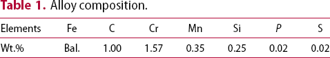
The commercial φ120 mm GCr15 hot-rolled bar was used as the material in this experiment. The chemical composition is shown in Table 1, taking the samples along the bar R/2 and machining them to the specified size (30 mm × 5 mm × 1.5 mm) by spark cutting. The schematic diagram of the equipment for electric field processing is shown in Figure 1. The sample surface was polished with SiC sandpaper and fixed tightly to the electrode. Then, the electrodes were connected to the power supply by copper wires. The thermocouple was soldered to the sample surface to measure the temperature. In the heat treatment experiments, the thermal field was provided by the tube resistance furnace. All the above processes were conducted in the argon atmosphere to prevent oxidation and decarburisation of samples.
Schematic of the experimental setup. Alloy composition.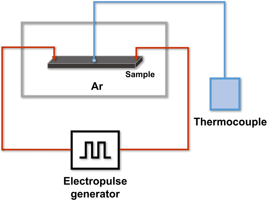
Pulsed electric current treatment and corresponding heat treatment
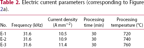
The effect of pulsed electric current on the microstructure was investigated by applying the current to the samples. As shown in Table 2 (corresponding to Figure 2a), the sample temperature (720 °C, 740 °C, 760 °C) was adjusted by changing the current density. Figures 2(b–d) present the temperature-time path of the pulsed electric current process and that recorded by the computer. After holding for 30 min, the samples were air-cooled to room temperature. In addition, to further analyse the carbide dissolution process under the electric field, the experiments at different durations (3 min, 10 min, 20 min) at 740 °C (E-2, 10.9 A mm−2) were also supplemented.
(a) Schematic of the experimental process, (b)–(d) the temperature-time paths of the pulsed and heat-treated processes. Electric current parameters (corresponding to Figure 2a).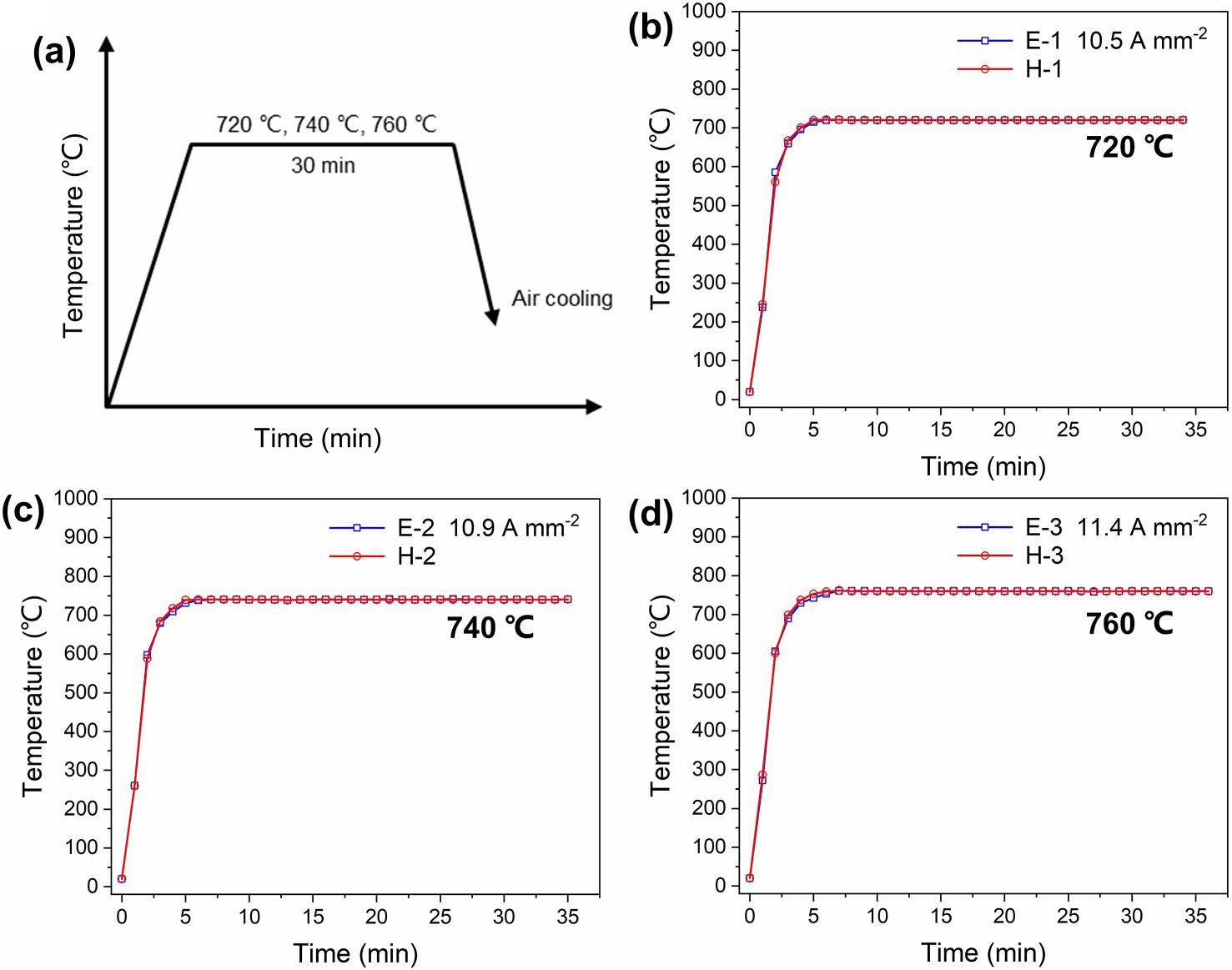
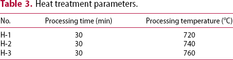
Heat treatment parameters.
Industrial annealing treatment
To elucidate the effect of pulsed electric current more clearly, some samples were treated with industrial annealing. The experimental parameters of annealing were referred to the current technological process and other experimental results [7,31]. The sample (G-1) was held at 800°C for 5 h and then cooled to room temperature during the annealing process.
Microstructure characterisation and simulation calculation
The samples were ground by sandpapers with different roughness and polished with silica solution until the surface was free of scratches. Then, the samples were etched with the ethanol solution containing 2% nitric acid for 60 s. The microstructure was analysed using the scanning electron microscope (SEM, JEOL JSM 6701F). Simultaneously, the original bar sample (Y-1) and the pulsed electric current treated samples were electropolished in the ethanol solution with 10% perchloric acid. The polishing process was cooled with liquid nitrogen to maintain the temperature at about −25 °C. The carbides were analysed by transmission electron microscopy (TEM, FEI Tecnai F30). The electron backscatter diffractometer (EBSD, OXINF Symmetry) was used to analyse the microstructure and crystal orientation of the matrix around the network carbides.
Furthermore, to analyse the effect of the pulsed process on carbides (size, morphology, distribution, etc.), the ImageJ software was used to complete the statistics of carbide, and more than 20,000 particles were counted for each sample to ensure the accuracy. Besides, the electric field model concerning carbide was constructed. The current distribution and electrical free energy changes during carbide dissolution were determined using MATLAB software.
Results
The carbide evolution in samples
Effect of pulsed electric current on the carbide dissolution
The original microstructure (Y-1) is shown in Figure 3(a). Many coarse and continuous network carbides are located along the grain boundaries, and lamellar carbides located within the grain (cementite) are interspersed with the matrix (ferrite). After the industrial annealing treatment (G-1), the cementite dissolved from continuous lamellae to fine particles. However, there were still many undissolved network carbide particles at the grain boundary (Figure 3b). The microstructures of pulsed samples are shown in Figures 4(a, c, e). At 720 °C, the network carbides at the grain boundary dissolved rapidly (only a small amount remained in some areas), and the intracrystalline carbides dissolved from lamellar to short rod shape (Figure 4a). As the temperature increases, the carbides are further dissolved. At 740 °C, the fine carbide particles dispersed uniformly in the matrix, and the coarse network carbide disappeared completely (Figure 4c). When the temperature increased to 760 °C, the carbides were dissolved basically. Many carbon atoms entered the austenite matrix, and martensite was formed during the cooling process (Figure 4e). In addition, the corresponding heat-treated samples are shown in Figure 4(b, d, f). At 720 °C, there was no obvious change in microstructure compared to the original sample (Y-1) (Figure 4b). As the temperature raised to 760 °C, many undissolved carbide particles can still be observed (Figure 4f).
SEM micrographs of the samples: (a) the original sample (Y-1), (b) the industrial annealed sample (G-1, 800 °C for 5 h). SEM micrographs of the pulsed electric current treated samples with different temperatures: (a) E-1, 720 °C for 30 min, (c) E-2, 740 °C for 30 min, (e) E-3, 760 °C for 30 min, (b, d, f) heat-treated samples under the corresponding conditions.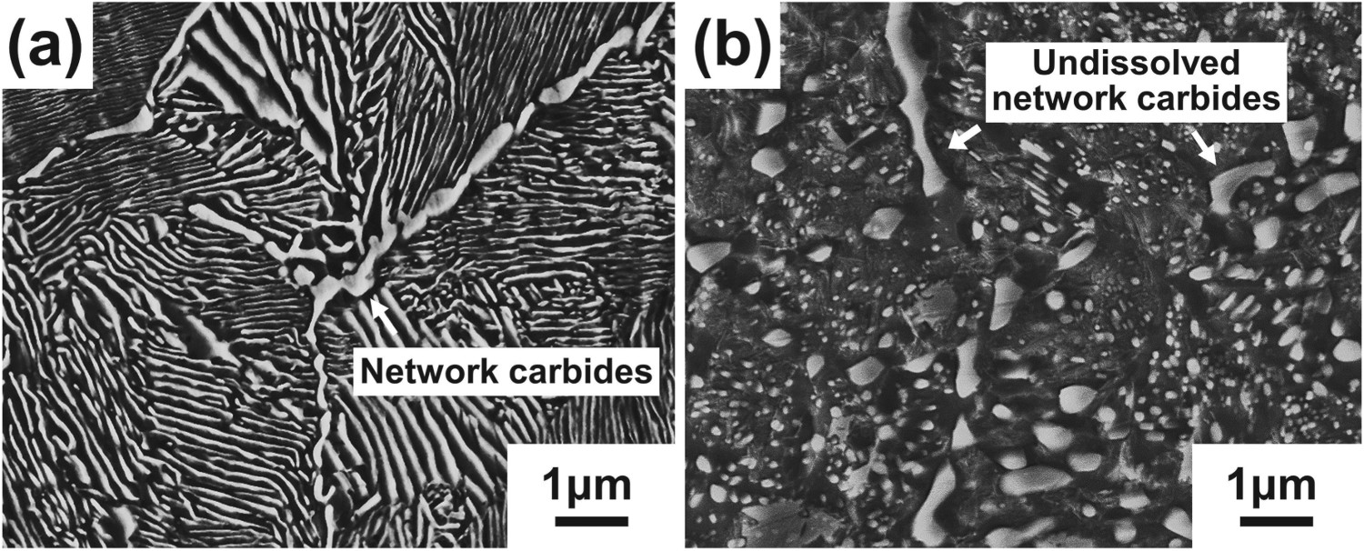
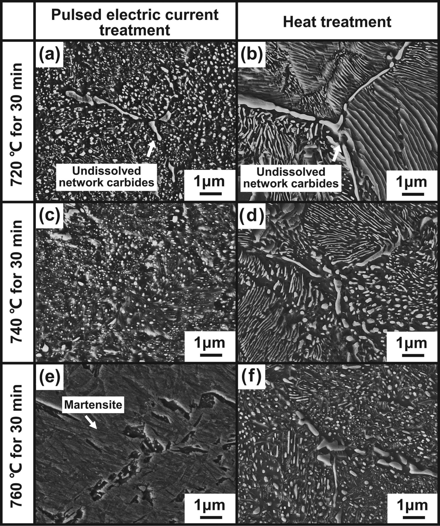
The above experimental results show that the pulsed electric current treatment significantly promoted carbide dissolution. Compared with heat treatment, at lower temperature and shorter time (740 °C for 30 min), the electric current achieved the same effect as industrial annealing treatment (high temperature, long process), i.e. the continuous distribution (lamellar, reticulated) carbides decomposed into spherical particles. More importantly, the current effectively eliminated the coarse network carbides that cannot be achieved by a single thermal field.
Quantitative analysis of carbides
To accurately reveal the effect of the pulsed electric current treatment, the carbide in the samples has been analysed quantitatively. Therefore, using ImageJ software to count the size and morphology of carbides in different samples, including the pulsed electric current treated sample (E-2), the heat-treated sample (H-2) under corresponding conditions and the industrial annealed samples (G-1). The results show that the current promoted the carbides (lamellar or reticulated) dissolved into spherical particles (length–diameter ratio < 2) effectively. The spheroidisation rate of the carbides was at the same level as that of the industrial annealed (800 °C for 5 h) sample (Figure 5). Besides, the corresponding heat-treated samples also contained a certain number of undissolved particles, but the carbide morphology was still dominated by rods and lamellae. The spheroidisation rate was only 4.89% (Figure 5a).
The percentage of spherical carbides (length-diameter ratio < 2) in the samples, including the pulsed electric current treated sample (E-2), the heat-treated sample (H-2) under corresponding conditions and the industrial annealed samples (G-1).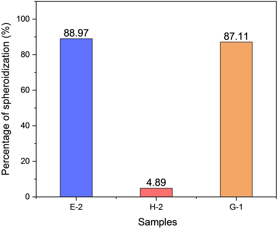
Furthermore, the particle size (equivalent circle diameter) distribution of carbides was counted, including the pulsed electric current treated sample (E-2) and the industrial annealed sample (G-1) (Figure 6). For the pulsed electric current treated sample, the particle size is distributed in the scope of 0.18–0.42 μm (81%). However, the carbide particle size of the annealed sample is highly non-uniform and distributed within the range of 0.18–4.38 μm. The above statistics show that the pulsed electric current significantly improves the carbide uniformity by eliminating the network carbides, which is conducive to the subsequent machining.
The carbide size distribution for the pulsed electric current treated sample (E-2) and the industrial annealed sample (G-1).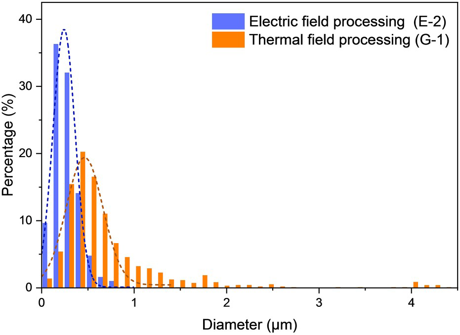
Dissolution behaviour of carbides under electric field
The dissolution rate of carbide particles with different sizes is identical under the single thermal field [32]. The particle size difference between network carbides and intracrystalline carbides is difficult to be reduced by heat treatment. In contrast, the experiment results show that the difference between carbides was significantly eliminated after pulsed electric current treatment TEM micrographs of samples treated by the pulsed electric current at E-2 parameters (740 °C with 10.9 A mm−2) for different durations. Intergranular region (10,000×): (a) 3 min, (c) 10 min, (e) 20 min, (g) 30 min. Intracrystalline region (30,000×): (b) 3 min, (d) 10 min, (f) 20 min, (h) 30 min.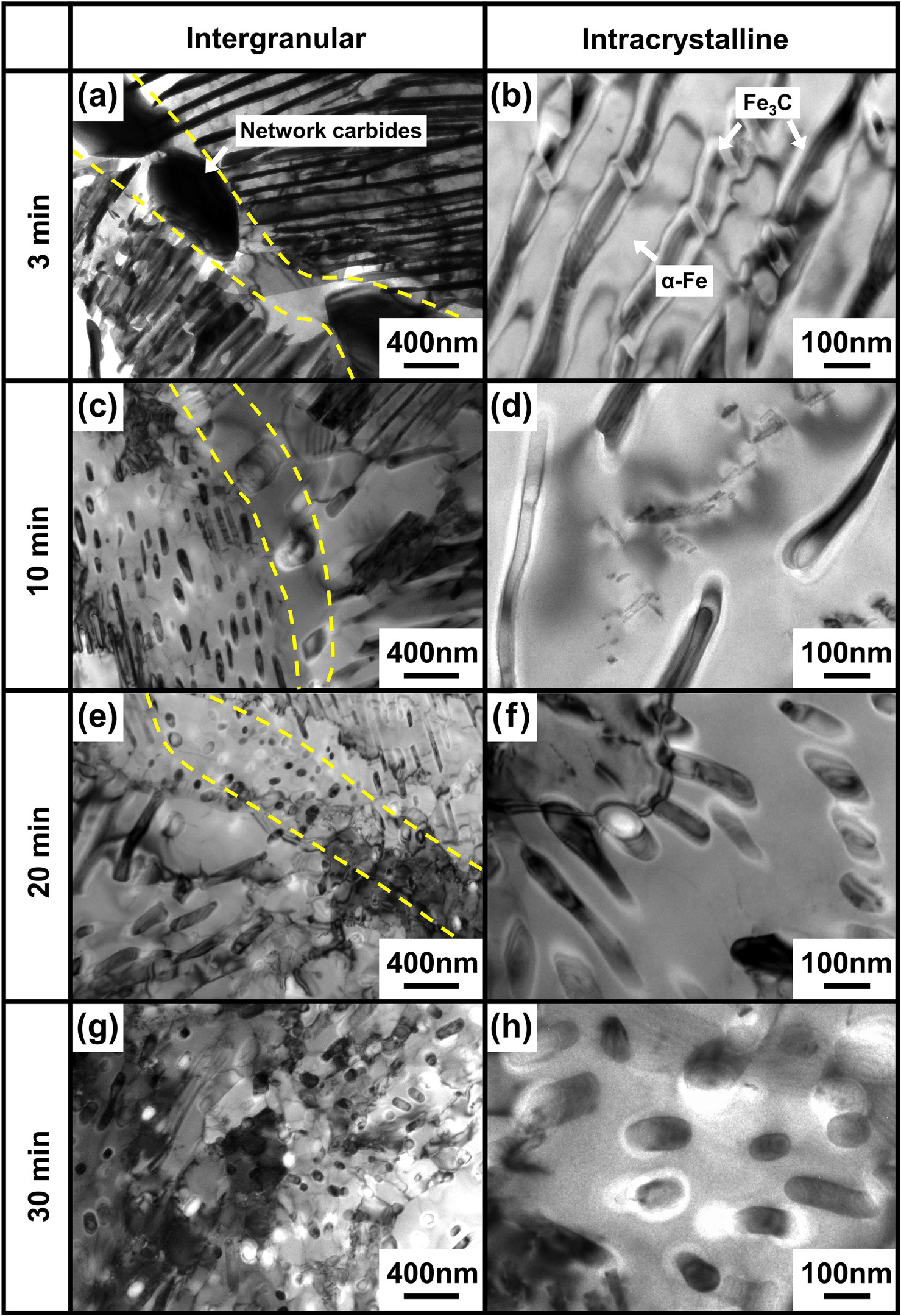
Based on the above results, the following conclusion was drawn. During the pulsed electric current treatment, there were differences in the carbide dissolution behaviour between different regions, that is, the dissolution rate of carbides in the intergranular region was faster. This leads to the network carbides dissolved preferentially under the electric field, thus eliminating the size difference with the intracrystalline carbides.
Effect of substrate on carbide dissolution
The above results show that the dissolution rate of carbide is related to its location (intracrystalline and intergranular). Therefore, it is necessary to analyse the matrix microstructure around carbides in depth. As shown in Figure 8(a, b), the network carbides were distributed along the prior austenite crystal boundaries, where the grain misorientation was at a high level. The grain misorientation within the carbide network was small, and the proportion of low-angle grain boundaries in this region was relatively high (Figure 8c). With the temperature increased in the annealing process, the matrix was transformed from ferrite to austenite. Owing to the inheritance of the microstructure during the phase transformation, the grain misorientation at the prior austenite crystal boundaries was still higher than that in the grain interior [33]. It is known from the literature [8,9], the atomic arrangement at the grain boundaries is chaotic, and there are many vacancies, dislocations and other defects, so the activation energy of grain boundary diffusion is lower than that of bulk diffusion. This effect increases gradually with the increase of grain misorientation within a certain range.
(a) Inverse pole figure Z of the original sample, (b) SEM micrograph of the original sample, (c) the distribution of grain orientation angle in the selected region.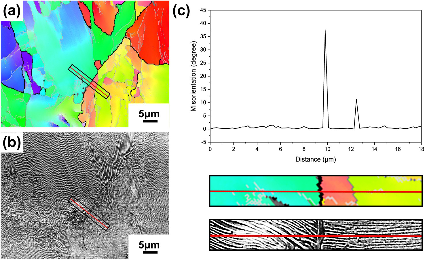
Based on the above results, it is assumed that the grain boundary was the fast diffusion path for carbon atoms, which promoted the preferential dissolution of the network carbides during the pulsed electric treatment. However, under the thermal field, the grain boundaries do not seem to have the same effect, and the difference in particle size between carbides still exists.
Discussion
Thermodynamic analysis of carbide dissolution
Effect of electrical free energy on carbide dissolution behaviour
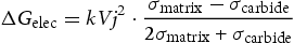
The carbide dissolution is required to meet a certain thermodynamic condition. Usually, the temperature of the system needs to reach the critical temperature for carbide dissolution. The experimental results show that the pulsed electric current can dissolve carbides at a lower temperature. In the electric field, additional electrical free energy will be generated due to the difference in conductivity between the matrix and the precipitate. The change of electrical free energy will significantly affect the precipitate dissolution, which is as follows [34]:
Numerical calculation of carbide dissolution in the electric field
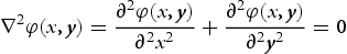
The experimental results show that the dissolution rates of network carbides and intracrystalline carbides were significantly different under the electric field (Figure 7). The coarse network carbide dissolved preferentially, which effectively eliminated the size difference between them. Furthermore, thermodynamic calculations and numerical modelling (bidimensional) were performed to explain the dissolution behaviour of carbides. Besides, under the pulsed electric current system, the potential obeys the Laplace Equations, which can be expressed as

The current distribution around the carbides was calculated by Equation (4). The results are carried over to Equation (2) for solving the electrical free energy. According to the original sample microstructure (Figure 3a), elliptical particles with different sizes were set in the model following the actual scale to represent the network carbides and intracrystalline carbides, respectively. Selected area electron diffraction (SAED) results confirm that the network carbide is the θ-Fe3C phase with the orthogonal crystal structure (Figure 9). It is the same with the intracrystalline carbide (θ-Fe3C). Therefore, all the carbides conductivities in the model are set to 1.2 × 10⁶ S m−1, and the matrix (γ-Fe) conductivity is 3.3 × 10⁶ S m−1 [35]. Set the system potential to 20 V and the electric field size to 4 µm × 4 µm.
Microstructure of the original sample. (a) TEM micrograph of the network carbide, (b) SAED pattern of the network carbide, [100]θ-Fe3C, (c) TEM micrograph of the intracrystalline carbide, (d) SAED pattern of the grain interior, [011]α-Fe // [101]θ-Fe3C.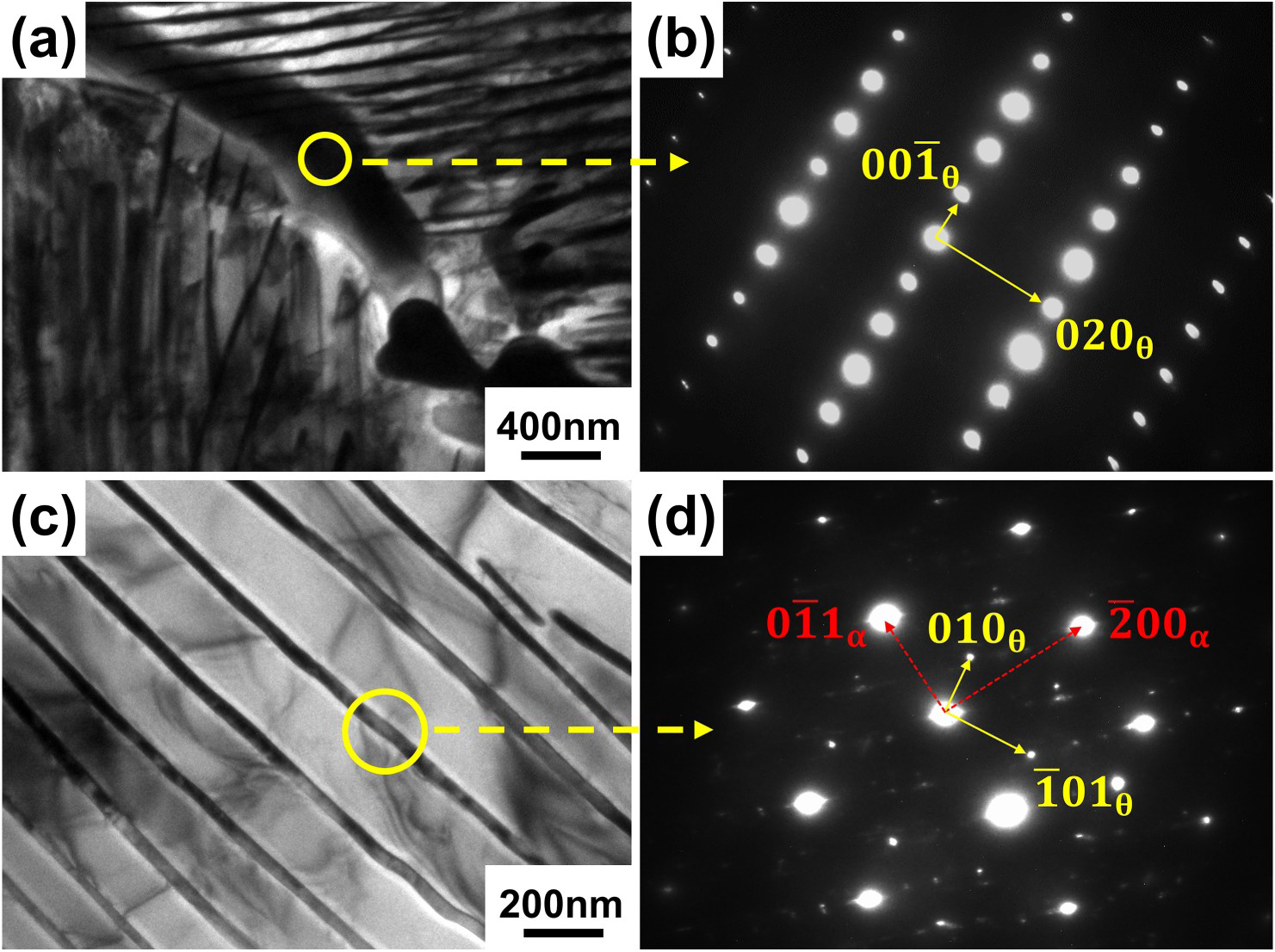
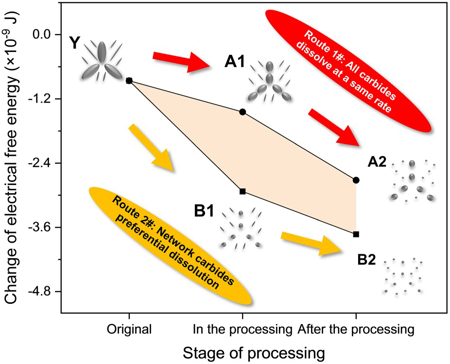
Combined with the experimental results (Figure 7), it is assumed that there are two possible evolution routes of carbides in bearing steel under the electric field. For route 1#, the dissolution rate of the network carbides and intracrystalline carbides remains the same, and the particle size between them always keeps a certain difference. For route 2#, the dissolution rate of the network carbides is faster than that of the intracrystalline carbides. The particle size difference gradually decreases as the reaction proceeds, and the residual carbide particles are small and uniform. As shown in Figure 10, to judge the correct evolution direction for the carbides under electric field, the carbide dissolution process was simulated by adjusting the particles sizes (Route 1#: Y → A1 → A2, Route 2#: Y → B1 → B2). The calculation results show that the change of electrical free energy caused by route 2# is much larger than that caused by route 1# (Figure 11). Qin and Dolinsky proposed that the reduction of electrical free energy is the driving force for structural evolution [36,37]. Under the action of the electric field, the material structure develops in the direction of reducing the free energy, that is, the electric current reduces the electrical resistivity, thereby obtaining a lower free energy system. Therefore, the carbides are more likely to dissolve according to route 2# during the process, i.e. the network carbide will dissolve preferentially.
The calculation results of the current distribution around carbides. Route 1# Y → A1 → A2, all carbides dissolve at the same rate, and the particle size difference is always maintained in the process. Route 2# Y → B1 → B2, network carbides dissolve preferentially, and the particles tend to homogenise in the process. Electrical free energy changes for different evolution routes of carbides. Route 1# Y → A1 → A2, all carbides dissolve at the same rate, and the particle size difference is always maintained in the process. Route 2# Y → B1 → B2, network carbides dissolve preferentially, and the particles tend to homogenise in the process.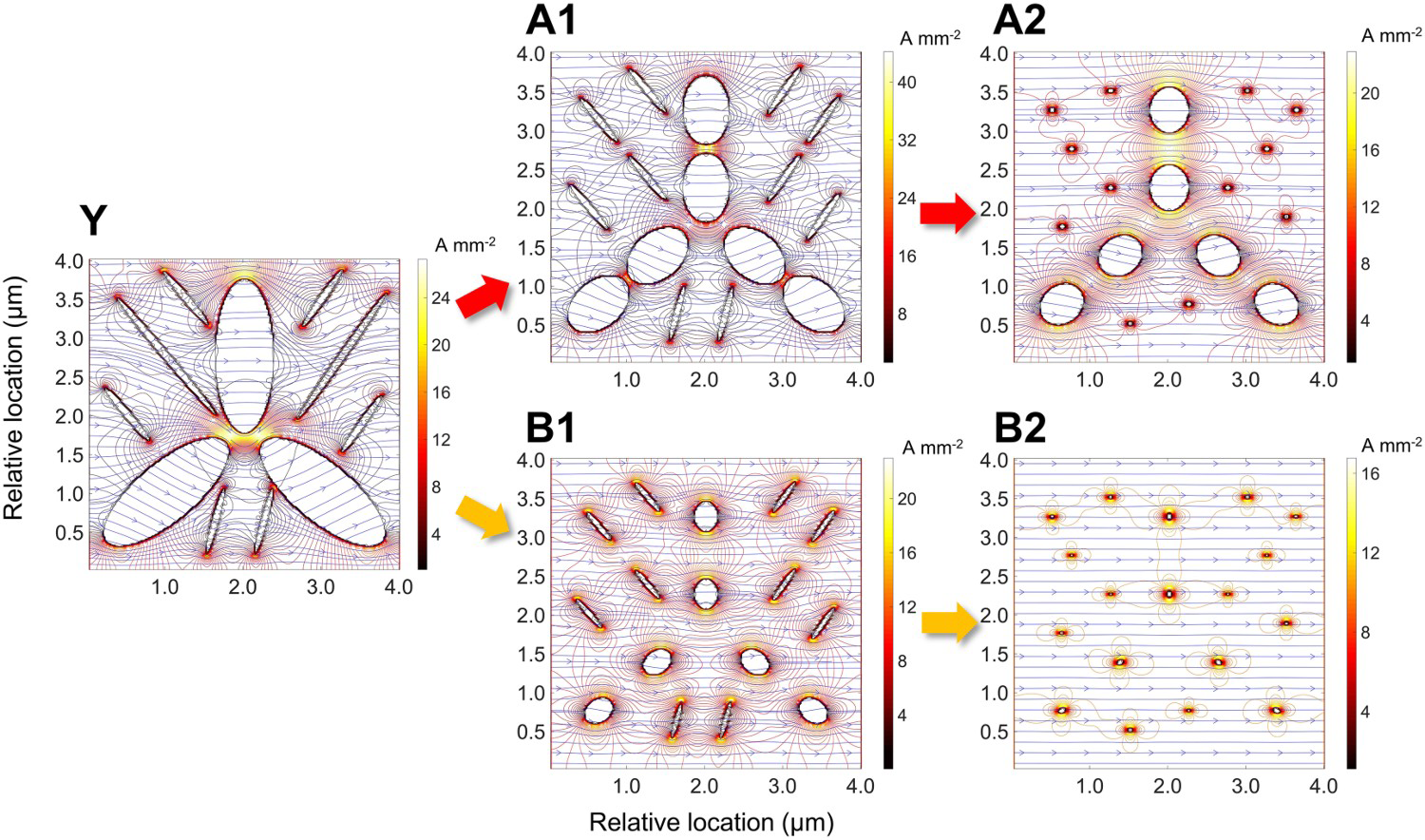
Kinetic analysis of carbide dissolution
Diffusion coefficient of carbon atoms under the electric field
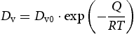
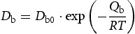
The experimental results show that the current increased the carbide dissolution rate (Figure 4). As the limiting link in the precipitate dissolution, atomic diffusion determines the reaction rate [38,39]. Since the carbon atom radius (77 pm) is smaller than that of the iron atom (117 pm), the diffusion mechanism of carbon atoms is interstitial diffusion. The bulk diffusion (intracrystalline diffusion) is the main diffusion pathway in solid metals under the thermal field, as follows [40]:


 [44]. The kinetic energy (ΔWe) received by atoms under the electric field can be expressed as

In this study, there was no microstructure evolution associated with the current direction. Therefore, the direction of electromigration was not considered. Under the electric field, the activation energy of diffusion can be expressed as

 can be given as
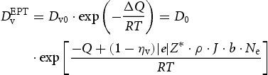
As seen in Equation (10), electromigration reduced the activation energy of atomic diffusion under the electric field, increasing the atomic diffusion rate. In addition, a higher current density will increase the number of electrons scattered to atoms, thus enhancing the electromigration effect. The following parameters were used for calculating the diffusion coefficient of carbon atoms: Dv0 = 2.34 × 10⁻⁵ m2 s−1 [45], Q = 147.81 kJ mol−1 [45], ηυ
= 0.83 [44], e = 1.6 ×10⁻¹⁹ C, Z* = 3.7 [46], b = 0.2543 nm [47], ρ = 2.16× 10⁻⁷ Ω m, Ne = 6.02 × 10²³ mol−1. The current density (J) is listed in Table 2. The calculated results are shown in Figure 12. The relationship between diffusion coefficient and temperature for different conditions (thermal and electric fields) is in agreement with the Arrhenius mechanism [47]. It can be seen that at 1013 K (740 °C), under the thermal field (without current), the diffusion coefficient of carbon atoms is 5.59 × 10⁻¹³ m2 s−1. However, the diffusion coefficient under the electric field was dramatically increased compared to the single thermal field. The diffusion coefficient of carbon atoms is 3.75 × 10⁻¹¹ m2 s−1 at J = 10.5 A mm−2. Compared to the thermal field, the diffusion coefficient increased by 67 fold. Further increasing the current density: when J = 10.9 A mm−2, the diffusion coefficient is 4.40 × 10⁻¹¹ m2 s−1 (increased by 79 fold); when J = 11.4 A mm−2, the diffusion coefficient is 5.38 × 10⁻¹¹ m2 s−1 (increased by 96 fold).
Diffusion coefficients of carbon atoms under the electric field and the thermal field (without current).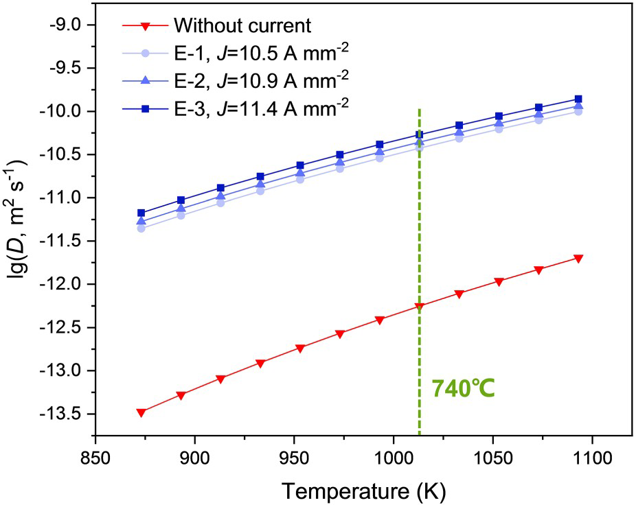
The above results show that the current significantly affects the diffusion rate. The diffusion coefficient increases with increasing current. Driven by electromigration, the carbon atoms obtained by dissolving carbides diffuse into the matrix, and the carbides dissolve rapidly. Pulsed electric current treatment shortens the process and improves the annealing efficiency.
The effect of electric field distortion
The current will be uniformly distributed as it passes through an ideal conductor (uniform conductivity). However, there is a significant difference in conductivity between the carbide and the matrix. The calculations show that as the current passed through the sample, it tended to bypass the high resistance region (carbide) and pass along the low resistance region (matrix) (Figure 13a, b). The current produces a high current density region on the carbide surface where the electric field is distorted.
(a) Schematic of the model (‘a’ and ‘b’ represent the long-axis radius and the short-axis radius of the particle), (b) schematic of the electric field (the lines with an arrow indicate the current, the ellipse indicates the carbide particle). (c, d) Calculated results of current distribution around the carbides: (c) network carbide (a = 1 μm, b = 0.4 μm), (d) intracrystalline carbide (a = 0.1 μm, b = 0.04 μm).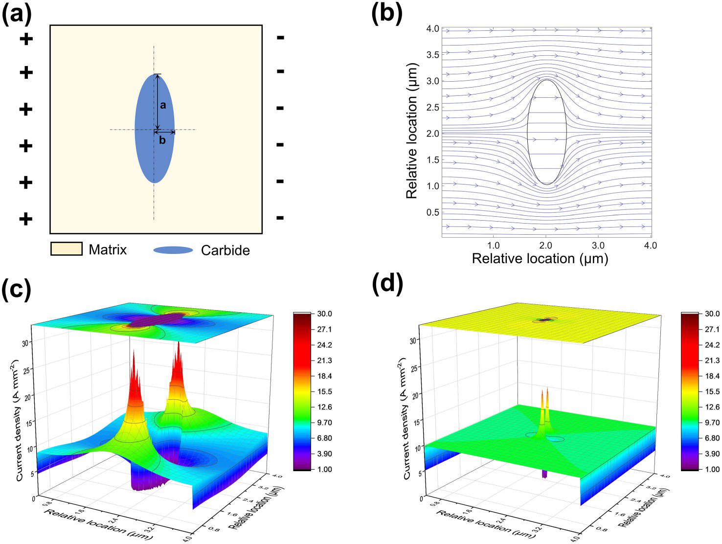
Furthermore, the current distribution around the carbides was analysed. The current density data in the model, corresponding to the particles and the surrounding area, were selected for comparison (network carbide, a = 1 μm, b = 0.4 μm; intracrystalline carbide, a = 0.1 μm, b = 0.04 μm). As shown in Figure 13, the electric field distortion caused by the network carbide and the intracrystalline carbide was different. Compared with the intracrystalline carbide, there was a larger high current density region on the surface of the coarse network carbide (Figure 13c, d). It is clear from the analysis in the previous section that the diffusion coefficient is proportional to the current density in the electric field. The stronger electron wind effect effectively increased the dissolution kinetics of network carbides.
Carbon atoms diffusion at the grain boundary
As a polycrystalline material, bearing steel has many vacancies, dislocations and other defects at the grain boundaries. During the processing, grain boundaries are fast diffusion paths for atoms, significantly affecting the material microstructure (Figure 7). To reveal the diffusion mechanism of carbon atoms at grain boundaries, it is necessary to quantify the diffusion of carbon atoms at grain boundaries under different conditions (electric field, thermal field). Similar to intracrystalline diffusion, the diffusion coefficient at grain boundaries also follows the Arrhenius mechanism, as follows [40]:
 , so the effective diffusion coefficients in the grain interior
  and grain boundary
  are as follows [40]:


The following parameters were used to solve the effective diffusion coefficient of carbon atoms at grain boundaries: Db0 = 2.51 × 10⁻³ m2 s−1 [45], Qb = 74.31 kJ mol−1 [45]. Also, the effective diffusion coefficient of carbon atoms under electric field (J = 10.9 A mm−2) was calculated by referring to Equation (10). The results are shown in Figure 14(a). Under different conditions (electric and thermal fields), the effective diffusion coefficients at grain boundaries were higher than those in the grain interior due to the lower activation energy. With the increase of temperature, the concentration of vacancies in the grains increases gradually, and the diffusion rate of carbon atoms inside the grains increases rapidly. The differences in diffusion coefficients gradually decrease and eventually tend to be the same.
(a) Diffusion coefficients of carbon atoms in different regions of the matrix (intracrystalline and intergranular) under electric and thermal fields, (b) Difference value of diffusion coefficients under pulsed electric current treatment (E-2, 740 °C) and industrial thermal annealing treatment (G-1, 800 °C).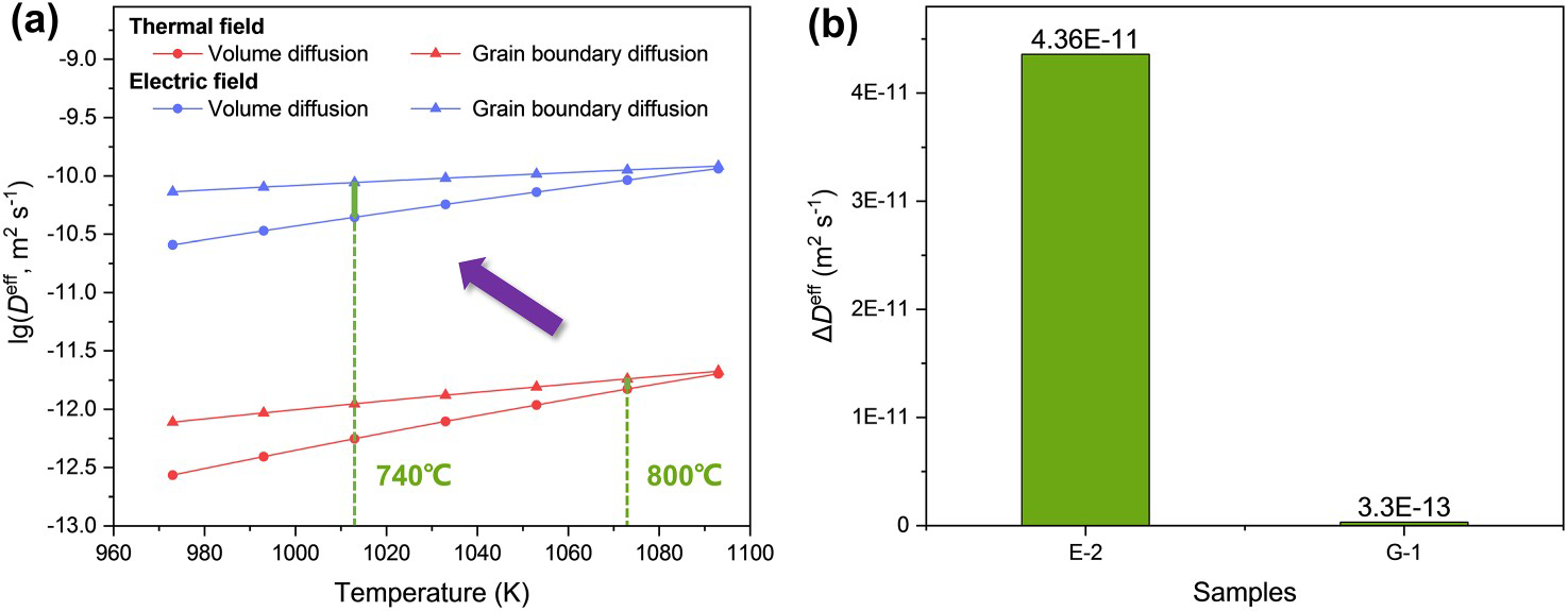
Furthermore, the carbon atom diffusion in the pulsed electric current treatment (E-2, 740 °C) and the industrial annealing treatment (G-1, 800 °C) were comparatively analysed. At a treatment temperature of 1073 K (800 °C), the effective diffusion coefficients of carbon atoms in the grain interior and grain boundary under the thermal field (without current) are 1.49 × 10⁻¹² m2 s−1, and 1.82 × 10⁻¹² m2 s−1, respectively. The effective diffusion coefficient difference 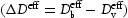 between them is 3.3 × 10⁻¹³ m2s−1. However, at a treatment temperature of 740°C and an electric field (J = 10.9 A mm−2), the diffusion coefficients of carbon atoms in the grain interior and grain boundary are 4.4 × 10⁻¹¹ m2 s−1 and 8.76 × 10⁻¹¹ m2 s−1, respectively, and the difference is 4.36 × 10⁻¹¹ m2 s−1. Compared with heat treatment, the difference in the effective diffusion coefficient increased by about 132-fold (Figure 14b).
The above calculations support the following conclusions. During the industrial annealing process, the difference in diffusion flux of carbon is small between the grain interior and grain boundaries. The kinetic conditions of carbide dissolution are almost the same. Under the action of the electric field, the electrical free energy reduces the annealing temperature, thereby increasing the effective diffusion coefficient difference between the grain interior and grain boundary. The electromigration increases the diffusion coefficient across the whole region, further amplifying the differences in the kinetics of carbide dissolution in different regions (intracrystalline and intergranular). More carbon atoms diffuse rapidly along the grain boundaries, which effectively promotes the dissolution of the network carbides.
To visually explain the process of carbide dissolution in bearing steel under electric and thermal fields, a schematic diagram of carbide dissolution and carbon diffusion is given (Figure 15). As shown in Figure 15(a), the concentration gradient promotes the diffusion of atoms in the thermal field, and the carbides dissolve slowly. A certain particle size difference between network carbides and intracrystalline carbides is always maintained. In contrast, electromigration effectively promotes the carbon atoms diffuse. Under the electric field, the network carbides dissolve rapidly with the effect of electric field distortion and grain boundary diffusion. The grain size difference between network carbides and the intracrystalline carbides is gradually eliminated, and the microstructure uniformity is finally improved (Figure 15b).
Schematic diagram of carbide dissolution for different processes. (a) During the heat treatment, the concentration gradient pushes the diffusion of atoms, and the carbides are slowly dissolved. (b) During the pulsed electric current treatment, with the combined effect of electromigration and grain boundary diffusion, the network carbides are dissolved rapidly, and the particle size difference between carbides is eliminated.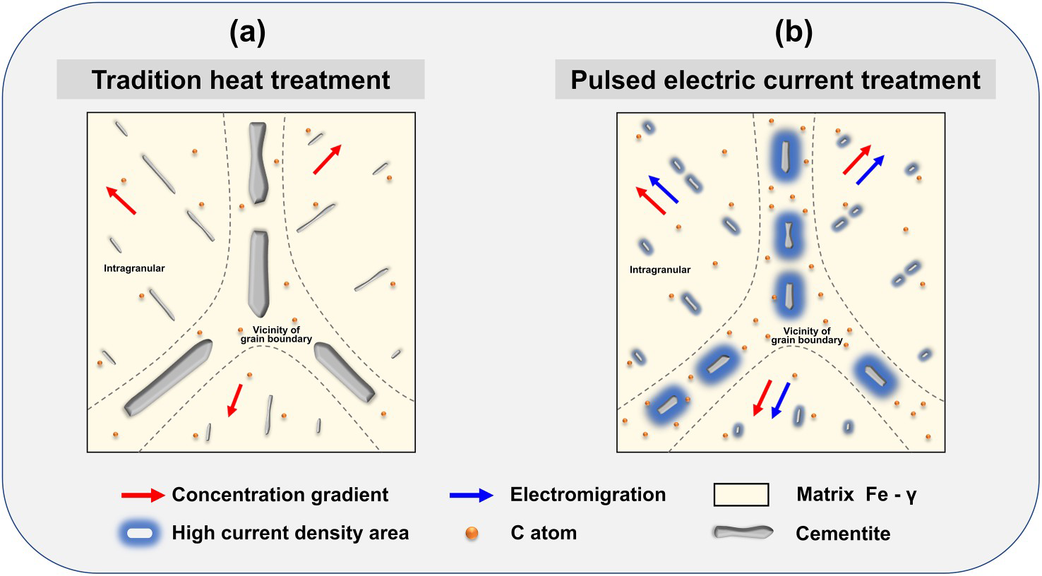
Conclusion
In summary, the electric field can significantly affect carbide dissolution and carbon atom diffusion. As a near-net-shaping forming technique, pulsed electric current processing can improve product quality and contribute to the development of steel manufacturing. This study provides theoretical support for achieving this goal. Following the above experimental evidence and discussion, the main conclusions obtained are as follows:
The pulsed electric current treatment (740 °C for 30 min) can effectively dissolve the network carbides in bearing steel. Compared with the industrial annealing treatment (800 °C for 5 h), the current significantly improved the microstructure uniformity and increased the processing efficiency. Thermodynamic calculations proved that the network carbides dissolved preferentially during the pulsed electric current treatment process. With the reaction, the size difference between carbides was eliminated. The diffusion coefficient of carbon atoms is proportional to the current density in the electric field. There is a large high-density current region on the surface of the coarse network carbide, and the strong electron wind force significantly improves its dissolution kinetics. There is a significant difference in dissolution kinetics of carbides in the intracrystalline and intergranular regions during the pulsed electric current treatment. Compared with the thermal field, the difference in diffusion coefficient (carbon atoms) between them is enlarged by a factor of 132.
Footnotes
Acknowledgements
The work was financially supported by National Natural Science Foundation of China (U21B2082; 51874023; U1860206), the National Key Research and Development Program of China (2019YFC1908403), Fundamental Research Funds for the Central Universities (FRF-TP-20-04B) and Recruitment Program of Global Experts.
Disclosure statement
No potential conflict of interest was reported by the author(s).