
Abstract
Ceramic particles reinforced iron matrix composites attract considerable interest in the industrial engineering field due to the ceramic's excellent fatigue and wear resistance. ZTA ceramic particle has been regarded as an ideal reinforcement phase. In this study, three-body abrasive wear behaviours and the mechanism of the ZTA/Fe composites and high chromium white cast iron Cr15 standard samples were investigated. The wear resistance of the ZTA/Fe composite was superior to the Cr15 standard sample under SiO2 abrasives. The extruded ZTA could protect the matrix surrounding ZTA ceramic particles. However, ZTA ceramic particles were cut together with the Cr15 matrix under SiC abrasives. The wear mechanism of the composites was a combination of the cutting and fatigue for SiC abrasives.
Introduction
Abrasive wear is one of the main failure modes for industrial applications such as mining, cement, concrete, and tunnel excavation [1-4]. The cutting and fatigue spalling of worn surfaces decrease the service life of the wear parts, resulting in enormous economic loss [5-9]. The novel ceramic particles reinforced iron/steel-based composites are expected to replace the traditional single alloys and intermetallic compounds due to the high hardness and modulus of ceramic particles and the excellent strength and plasticity of metallic matrix [10-12]. Generally, the ceramic particles as reinforcement phases for iron matrix include TiB x , Al2O3, ZrO2, SiC, TiC, WC, and VC [13-16]. The Al2O3 ceramic with high hardness, wear resistance, and low cost is a potential reinforcement phase in the iron-based composites [17]. However, Al2O3 ceramic has low fracture toughness and high contact angle with iron or steel matrix. These intrinsic drawbacks limit the application prospect of the Al2O3 ceramics in the wear resistance materials. ZrO2 toughened Al2O3 (ZTA) ceramics have an excellent self-enhanced toughness effect (t-ZrO2 to m-ZrO2), which effectively resists impacting force, cutting, and fatigue wear [18,19]. Meanwhile, ZrO2 ceramic has a lower contact angle with iron matrix than that of the Al2O3 ceramic [20-22]. Some researchers [23-28] reported that the interfacial bonding of composites is a critical factor for evaluating the mechanical and wear resistance properties. The mediocre interfacial bonding of the composites causes peeling-off of the ZTA ceramic particles from the iron matrix, leading to premature failure under the harsh wear service conditions [29]. Li et al. [30] and Ru et al. [31] successfully improved the interfacial bonding of the ZTA/Fe composites by the active metallic coatings on the ZTA ceramic particles’ surface. The wear resistance of the ZTA/Fe composites could be enhanced by improving interfacial bonding. Ru et al. [31] investigated the impact-abrasive-wear resistance of the Ni-activated ZTA ceramic particles reinforced high manganese steel matrix composites. The results indicated that the wear resistance of the composites could be enhanced due to the formation of an interfacial diffusion layer between the iron matrix and ZTA ceramic particles. Zheng et al. [32] reported that the three-body-abrasive-wear resistance of the ZTA reinforced Cr26-based composites improved up to 5%, which was attributed to the introduction of the titanium binder.
On the other hand, the favourable fabrication technique can also improve the wear resistance of composites [33,34]. Qiu et al. [33] found that the relative wear resistance of the ZTA reinforced Cr26-based composites prepared by pressure casting was higher than that of the composites prepared by infiltration casting due to their tight interfacial bonding. Zhou et al. [34] reported that the three-body wear resistance of the ZTA reinforced Cr26-based composites assisted by a continuous and compact transition layer was higher than that of the Cr26 standard samples and the bare ZTA reinforced Cr26-based composites.
The purpose of this study is to clarify the three-body wear evolution and mechanism of the ZTA/Fe composites under the SiC and SiO2 abrasives. Whereafter, the interaction of the ZTA ceramic particles and iron matrix will be investigated during the three-body abrasive wear process.
Experimental procedures
Sample preparation
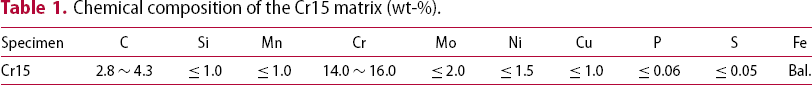
Chemical composition of the Cr15 matrix (wt-%).
Three-body abrasive wear test and characterisation
The ZTA/Fe composites were cut by abrasive waterjet and automatic precision cutting machine, then ground by SiC sandpaper (120–800 mesh) and polished to 1 µm roughness using flannelette. The wear surface dimension of the test samples was 15 mm × 25 mm. The wear tests were carried out in block-on-ring three-body abrasive wear equipment, as seen in Figure 1 [35]. Before the test, the samples were fixed in the holder and covered by loose abrasives. The samples horizontally slipped against the ring-shaped counter trajectory (Figure 1). The distance from the samples to the axis was retained at 340 mm. In order to explore the effects of abrasive types and abrasive sizes on the wear behaviour and mechanism, the three-body abrasive wear tests of the samples were carried out under the SiO2 abrasives (20–40, 40–70, 70–140 mesh) and SiC abrasives (40–70 mesh), respectively. During the wear, the applied loads were 1, 2, and 3 kg, and the sliding velocity was 30 r·min−1. The total wear duration of each test was 360 min, and the sample weight was tested every 30 min. The new sands were replaced after each test duration to eliminate the ‘size effect’ of the abrasive sand. The mass changes before and after test were used for evaluating the wear resistance of the samples [9,11,18,21-23,32-34]. The mass loss was the average value of three group experimental data to guarantee reproducibility. A scanning electron microscope (SEM) was used for characterising the interfacial microstructures and worn morphologies. The three-dimensional (3D) profile and surface roughness were measured via a 3D laser scanning confocal microscope (LSCM).
Schematic diagram of the three-body abrasive wear equipment: (a) actual experimental equipment; (b) wear system; (c) wear principle; and (d) sample size.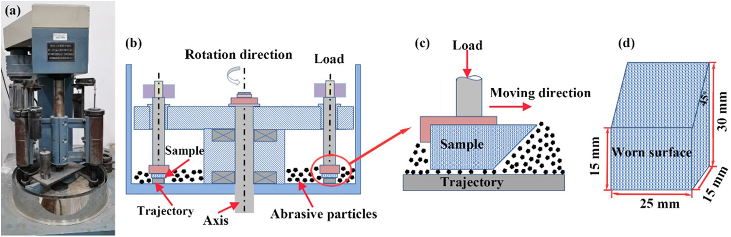
Results and discussion
Microstructures of the ZTA/Fe composites
Figure 2 shows the microstructure and elements distribution nearby the interfacial layer of the ZTA/Fe composites. The brown region represents the Cr15 matrix, including iron matrix and carbides (M7C3, M = Cr, Fe). Meanwhile, it can be seen that the irregular ZrO2 ceramics are uniformly distributed in the Al2O3 ceramics. The hardness of the ZTA ceramics is 1800 HV. A continuous transition layer occurs in the interfacial layer of the ZTA/Fe composites, as seen in Figure 2(a). From Figure 2(c, d), Ni and Cr from the interface diffuse to the Cr15 matrix, which is attributed to the high diffusion coefficient of the active metallic atoms [36]. After infiltration casting, some residual spherical Ni–Cr alloys retain in the interface between ZTA ceramic particle and the Cr15 matrix (see Figure 2(a, c, d)). The elements analysis results indicate that the transition layer is silicates, which closely bond ZTA ceramic particles and the Cr15 matrix. During the ceramic preform preparation, the aqueous solution of the borax and silicate is used as the binder for coated ZTA ceramic particles and Ni–Cr powders. The introduced silicate solution may promote adhesiveness between Ni–Cr powders mixture and ZTA ceramic particles. Yang et al. [37] also reported that the whiskers reinforced borosilicate glasses as binders could adhere to the ZTA ceramic bulks.
SEM micrographs of the ZTA/Fe composites (a) and elements distribution nearby interface (b-f).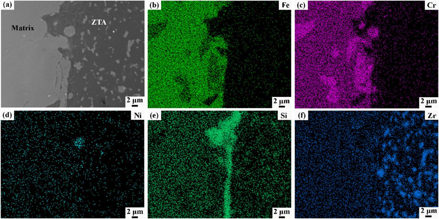
Wear behaviour of the ZTA/Fe composites and the Cr15 standard samples in the case of SiO2 sand
The mass losses of the ZTA/Fe composites and the Cr15 standard samples after three-body wear (against the SiO2 abrasives) are shown in Figure 3. Figure 3(a and b) reveals the mass loss variation of the ZTA/Fe composites and the Cr15 standard samples under 70–140 mesh abrasives. The mass losses of the ZTA/Fe composites and the Cr15 standard samples all increase with an increasing wear duration. Meanwhile, applied loads aggravate the material removal resulting in increasing mass loss. Combined Figure 3(a and b), the rise speed of the ZTA/Fe composites is lower than that of the Cr15 standard samples due to the ‘protective effect’ of the ZTA ceramics. The ZTA ceramic with high hardness can resist the cutting and impacting force during the three-body abrasive wear [38]. The mass loss variations of the ZTA/Fe composites and the Cr15 standard samples with the abrasive size are shown in Figure 3. Figure 3(c–f) presents the mass loss curves of the ZTA/Fe composites and the Cr15 standard samples under 40–70 mesh and 20–40 mesh SiO2 abrasives, respectively. It can be noted that materials removal becomes more serious with increasing abrasive size. According to the cumulative mass loss, in the case of 40–70 mesh abrasives, the wear resistance of the ZTA/Fe composites is 1.81–1.57 times than that of the Cr15 standard samples when the applied loads from 1 to 3 kg (see Figure 3(c,d)). The ‘protective effect’ of ZTA ceramics for the Cr15 matrix will weaken when increasing load. The high applied load may promote ZTA ceramic particles shedding from the matrix during the three-body wear process. On the condition of 20–40 mesh abrasives, the wear resistance of the ZTA/Fe composites is 1.47–2.06 times than that of the Cr15 standard samples (Figure 3(e, f)). The excellent relative wear resistance between the ZTA/Fe composites and the Cr15 standard samples is attributed to the protective effect of the ZTA ceramic particles. The abrasive size and applied load will affect the wear resistance of ZTA/Fe composites and the Cr15 standard samples in the condition of the SiO2 abrasives [39,40].
Variation of mass loss of the ZTA/Fe composites and the Cr15 standard samples with wear duration under the SiO2 abrasives: (a, b) 70–140 mesh sands; (c, d) 40–70 mesh sands; and (e, f) 20–40 mesh sands.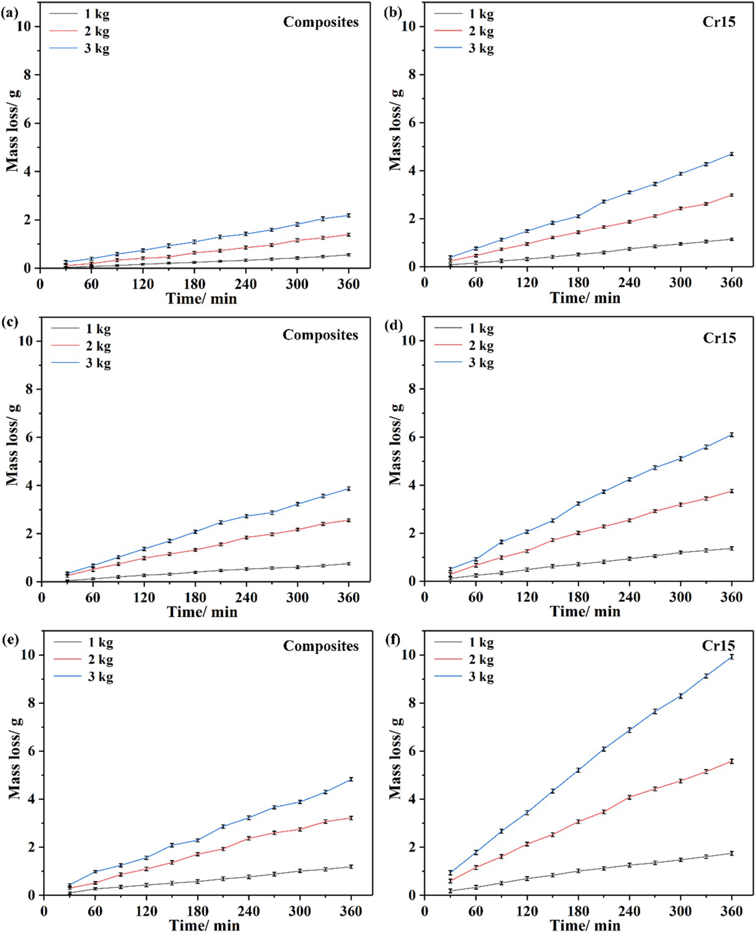
The worn morphologies of the ZTA/Fe composites under 40–70 mesh SiO2 abrasives are observed (see Figure 4). From Figure 4(a1, a2), the protruded ZTA ceramic particles appear on the worn surface of the ZTA/Fe composites due to the high hardness of ZTA ceramic (under 1 kg applied load). According to Richardson's theory [41], if H
m
/H
a
> 0.8 (where H
m
and H
a
are the hardness of the specimen and abrasive, respectively), the abrasive is regarded as ‘soft abrasive’; if H
m
/H
a
< 0.8, the abrasive is viewed as ‘hard abrasive’. Therefore, the SiO2 (1200 HV) abrasives represent ‘soft abrasive’, which can mostly cut and remove the Cr15 matrix, but hardly damage the ZTA ceramic during the three-body wear. The extruded ZTA ceramic particles can resist the wear action of the SiO2 abrasives cause protecting the surrounding matrix, which is consistent with the excellent wear resistance (see Figure 3). On the contrary, the high-strength Cr15 matrix supports the ZTA ceramic particles to avoid the peeling-off of reinforcement particles. The ZTA ceramic particles retain tight bonding with the Cr15 matrix by a transition layer assisting. Meanwhile, the worn surfaces of the ZTA/Fe composites seem clean without embedded SiO2 particles. Figure 4(b1 and b2) display the worn morphologies of the ZTA/Fe composites under 2 kg applied load, forming a wide concave slope among the ZTA ceramic particles. The Cr15 matrix suffers serious cutting, impacting, extruding, and rolling from SiO2 abrasives during the three-body abrasive wear. The high applied load accelerates Cr15 matrix removal caused by increasing kinetic energy of the SiO2 abrasive [42,43]. Meanwhile, some broken SiO2 abrasives will embed into the Cr15 matrix under 2 kg applied load. For the over-high load (3 kg), the ZTA ceramics occur delamination and exfoliation with the removal of the Cr15 matrix. Therefore, numerous fine SiO2 abrasives aggregate and embed into the interface of the ZTA/Fe composites under a 3 kg applied load. According to the interfacial morphologies (see Figure 4(a2–c2)), the interfacial slope between the ZTA ceramic particles and the Cr15 matrix gradually decreases with an increasing applied load, indicating that applied load promotes ZTA ceramics removal during the three-body abrasive wear. The ZTA ceramics occur breaking and peeling off under the continuous impacted and fatigued force. The exfoliated ZTA ceramics can also cut the surface of the Cr15 matrix, forming the deep plowing nearby the interface between ZTA ceramic particles and the Cr15 matrix.
SEM micrographs of the ZTA/Fe composites after wear (against SiO2 abrasives): (a1, a2) 1 kg; (b1, b2) 2 kg; and (c1, c2) 3 kg.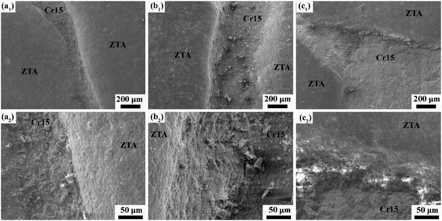
The influence of applied load on the worn morphologies and roughness is evaluated utilising 3D laser scanning microscopy. Figure 5(a) displays the 3D profile morphologies of the ZTA/Fe composites after three-body abrasive wear (against SiO2 sands) under the 1 kg applied load. The worn surface of the ZTA/Fe composites appears some shallow concaves of the Cr15 matrix and the humps of the ZTA ceramics. These results indicate that the ZTA ceramics protrude 285.5 µm above the Cr15 surface and the roughness retains 26.220 µm. It can be seen that the surface roughness and the height difference of the ZTA/Fe composites first increase and then decrease with an increasing applied load. The applied load can also aggravate the removal of the Cr15 matrix, forming an obvious height difference between ZTA ceramics and the Cr15 matrix. On the condition of 2 kg applied load, the ZTA/Fe composites have a large height difference and roughness caused by interaction between abrasive and applied load.
3D LSCM topography and roughness of the ZTA/Fe composites after three-body abrasive wear (against SiO2 abrasives): (a, d) 1 kg; (b, e) 2 kg; and (c, f) 3 kg.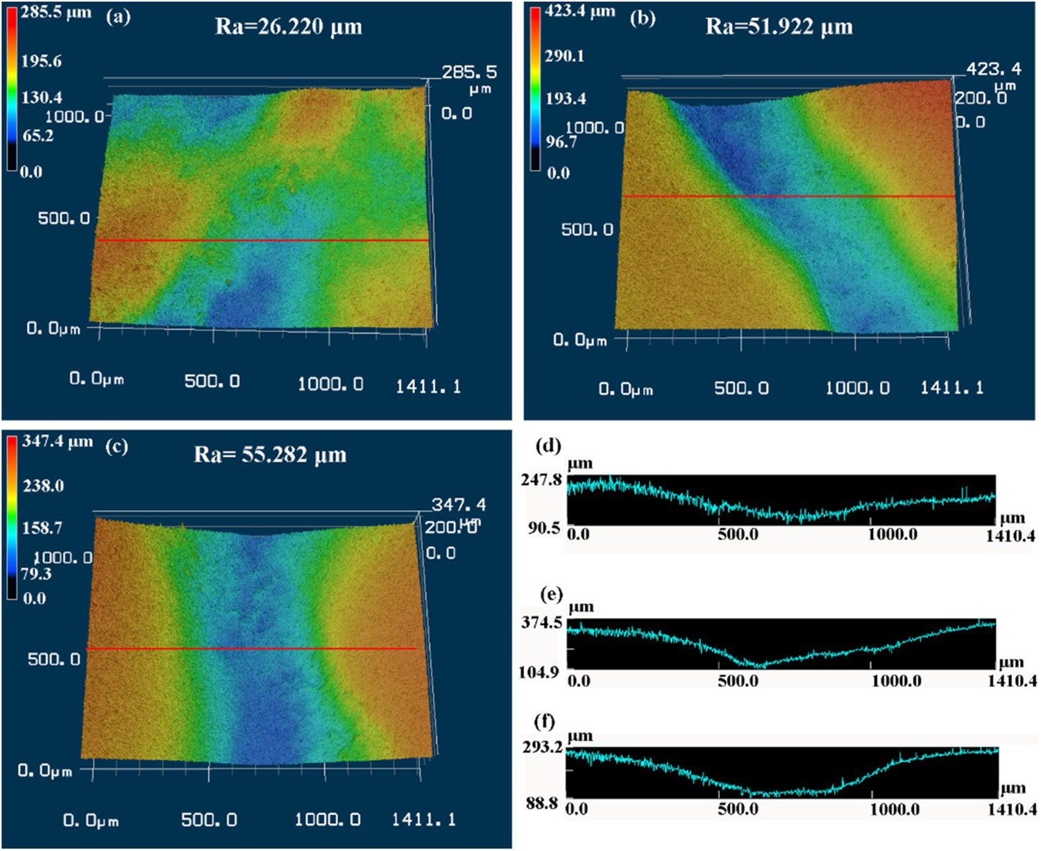
The morphologies and 3D profiles of worn surfaces indicate that the ZTA/Fe composites have lower roughness and interfacial slope after three-body abrasive wear under 3 kg applied load than in the case of 2 kg (Figures 4 and 5). However, the mass loss of the ZTA/Fe composites on the condition of 3 kg is higher than that of 1 and 2 kg. To further explain these opposite phenomena of the interfacial slope, surface roughness, and mass loss under different applied loads, the macro morphologies of the SiO2 abrasives are observed (Figure 6). The abrasive size is about 400–600 µm after abrasive wear under 1 kg applied load, which is larger than that of 3 kg applied load. Additionally, some finely crushed particles can be observed among large-size abrasives. During the abrasive wear process, SiO2 abrasives severely remove the Cr15 matrix (cutting, rolling, and fatiguing wear) under low applied load but mildly damage the ZTA ceramics. High applied load exacerbates impacting action of the SiO2 abrasive on the ceramics surface, causing delamination and skinning [39]. Therefore, the breaking phenomenon of SiO2 abrasive is more serious under the high applied load (see Figure 6(c)).
Morphology of the SiO2 abrasives after three-body wear: (a) 1 kg; (b) 2 kg; and (c) 3 kg.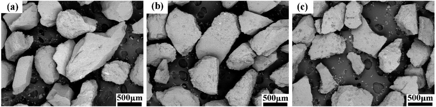
The worn surface of the Cr15 standard samples was observed (40–70 mesh SiO2 abrasive). Figure 7(a1, a2) shows the worn morphologies of the Cr15 standard samples under 1 kg applied load. As observed, the worn surface of the Cr15 standard sample displays plowing, micro-cutting, delamination, and crack. SiO2 abrasives cut and impact the Cr15 surface, leading to the removal and damage of the materials [44]. The repeated rolling and impacting of the SiO2 abrasives cause fatigue wear on the Cr15 surface. Therefore, some fatigue cracks can be found in the plowing grooves. Figure 7(b1, b2) presents the worn morphology of the Cr15 standard samples under 2 kg applied load. It can be observed that the width and length of plowing grooves significantly increase under the high load. Meanwhile, the fatigue deforming of the Cr15 surface under 2 kg is more serious than that of the condition of 1 kg load. When the alternating impact force reaches a certain extent, the abrasives will embed into the worn surface of the Cr15. Additionally, some broken abrasives remain in the plastic deformation cavities and deep furrows under 3 kg applied load.
SEM micrographs of the Cr15 standard samples after wear (against SiO2 abrasives): (a1, a2) 1 kg; (b1, b2) 2 kg; and (c1, c2) 3 kg.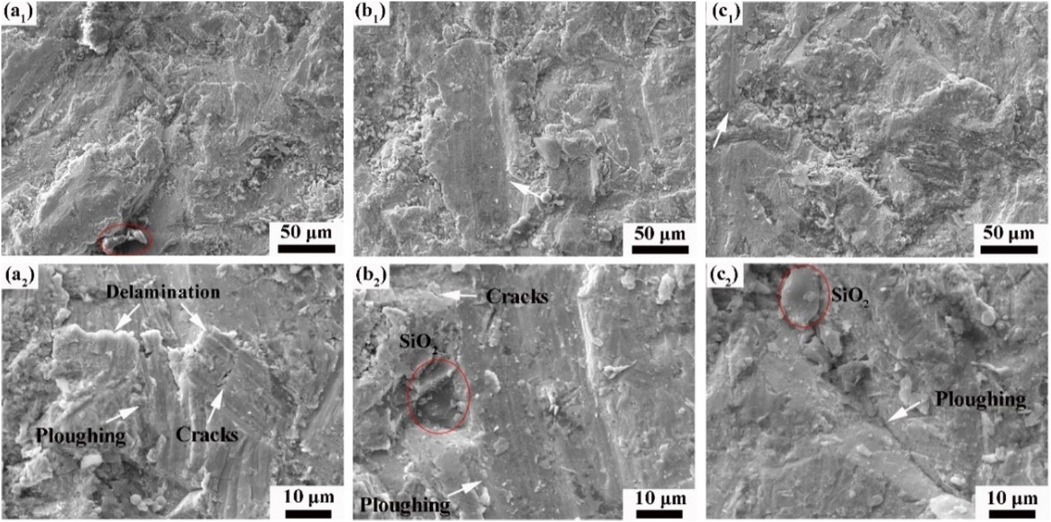
Wear behaviour of the ZTA/Fe composites and the Cr15 standard samples under SiC abrasives
The influence of applied load on the wear resistance of the ZTA/Fe composites and the Cr15 standard samples (against SiC abrasives) were also investigated to provide an insight into the wear behaviour and mechanism. Figure 8 shows the mass loss variations of the ZTA/Fe composites and the Cr15 standard samples. In the case of SiC abrasives, the mass loss of the ZTA/Fe composites and the Cr15 standard samples increase with an increasing applied load. However, the mass loss of the ZTA/Fe composites is higher than that of the Cr15 standard samples, which is opposite to the condition of the SiO2 abrasives. Considering the cutting and shedding of the ZTA ceramic particles together with the Cr15 matrix, it is reasonable for the unsatisfactory wear resistance. The low difference in the mass loss between the ZTA/Fe composites and the Cr15 standard samples may be attributed to ceramic particle's serious failure under the high hardness SiC abrasives.
Mass loss of the ZTA/Fe composites and the Cr15 standard samples under SiC abrasives.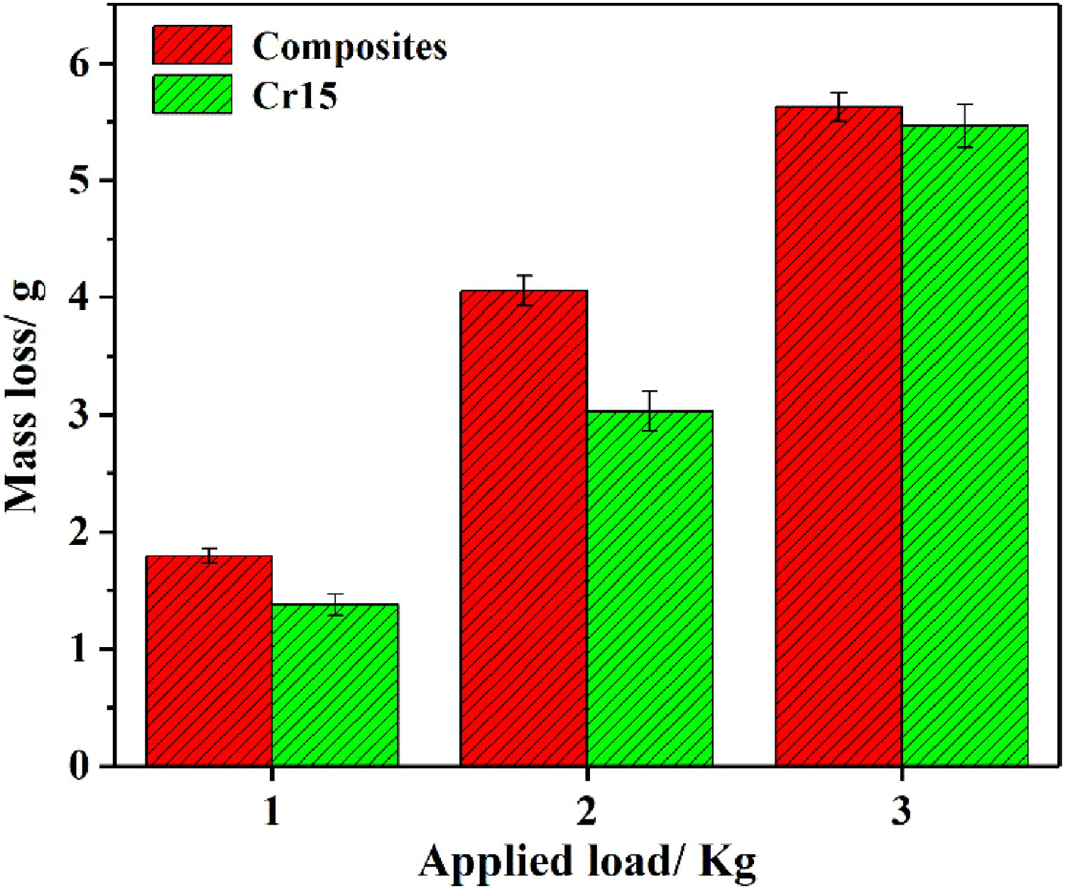
Figure 9 shows the worn morphologies of the ZTA/Fe composites after abrasive wear (against the SiC sands). Figure 9(a2–c2) represents high-magnification microstructure of the red rectangles from Figure 9(a1–c1). The ZTA ceramic particles have almost the same height as the Cr15 matrix under 1 kg applied load (see Figure 9(a1, a2)). Based on Richardson's theory [41], the SiC sand (2600 HV) is ‘hard abrasive’. During the three-body abrasive wear, the SiC can cut ZTA ceramics and the Cr15 matrix. From Figure 9(a2), the Cr15 matrix tightly connects with the ZTA ceramics; the transition layer width is about 50 µm. The Cr15 matrix is higher than that of ZTA ceramics under a load of 2 kg, as seen in Figure 9(b1, b2). These results are consistent with the mass loss variations of the ZTA/Fe composites and the Cr15 standard samples. Additionally, the worn surface of the ZTA/Fe composites appears clean and smooth platform. In the case of a 3 kg applied load, many peeling-pits and delamination emerge on the worn surface of metallic matrix, which belongs to a typical fatiguing wear structure. By comparison, it can be seen that the crushed SiC particles embed into the Cr15 matrix, which are caused by impacting and rolling. The compressional deformation and embedded SiC abrasives can restrain the removal of the Cr15 standard samples.
SEM micrographs of the ZTA/Fe composites after wear (against SiC abrasives): (a1, a2) 1 kg; (b1, b2) 2 kg; and (c1, c2) 3 kg.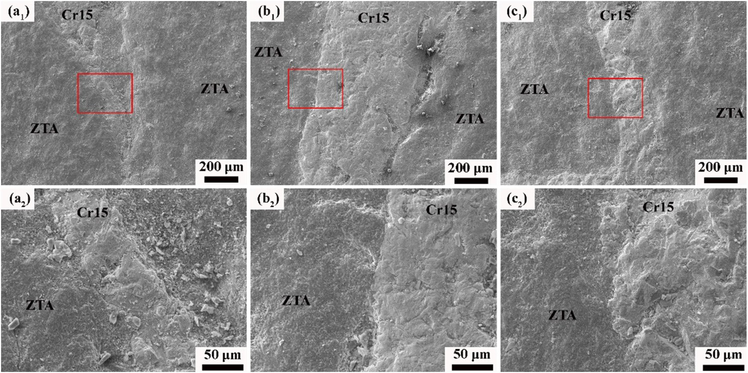
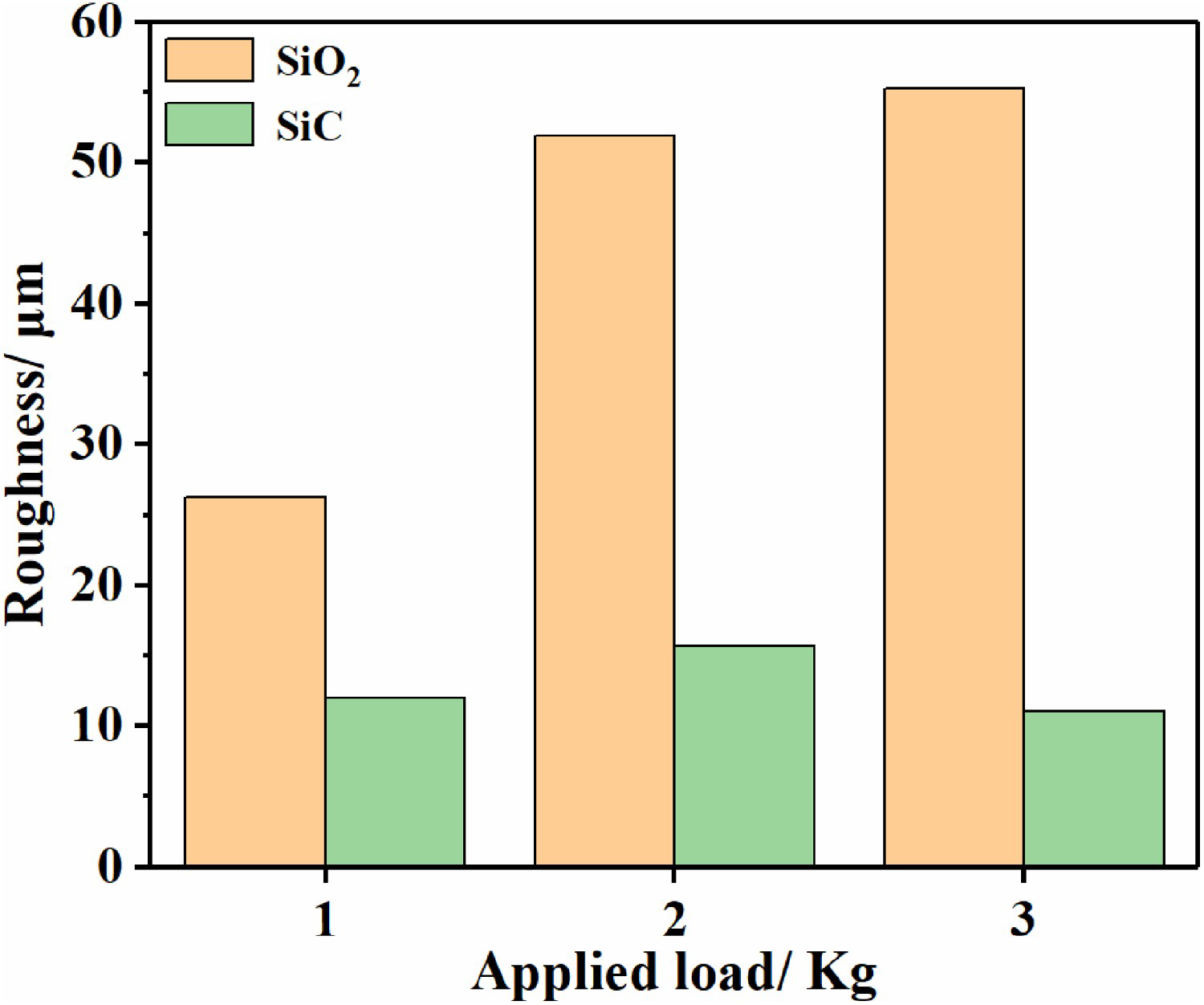
The 3D topography and roughness of the ZTA/Fe composites after three-body abrasive wear are depicted in Figure 10. The worn topography characteristics of the ZTA/Fe composites under the SiC abrasives prominently differ from the SiO2 abrasive condition. Based on the results of Figures 5 and 10, the worn roughness of the ZTA/Fe composites (SiO2 and SiC abrasives) is shown in Figure 11. Compared with the results of SiO2 abrasives condition, the wear roughness and height difference between ZTA ceramics and the Cr15 matrix is low under the SiC abrasives, which is consistent with the microstructure and mass loss. The ZTA/Fe composites roughness increases and then decreases with an increasing applied load under the SiC abrasive. ZTA ceramics and the Cr15 matrix will be removed together caused by the cutting and the rolling of the high hardness SiC abrasives [45,46]. High applied load prompts the material's fast removal, forming a smoother worn surface and relative lower worn roughness.
3D LSCM topography and roughness of the ZTA/Fe composites after three-body abrasive wear (against SiC abrasives): (a)(d) 1 kg; (b)(e) 2 kg; (c)(f) 3 kg.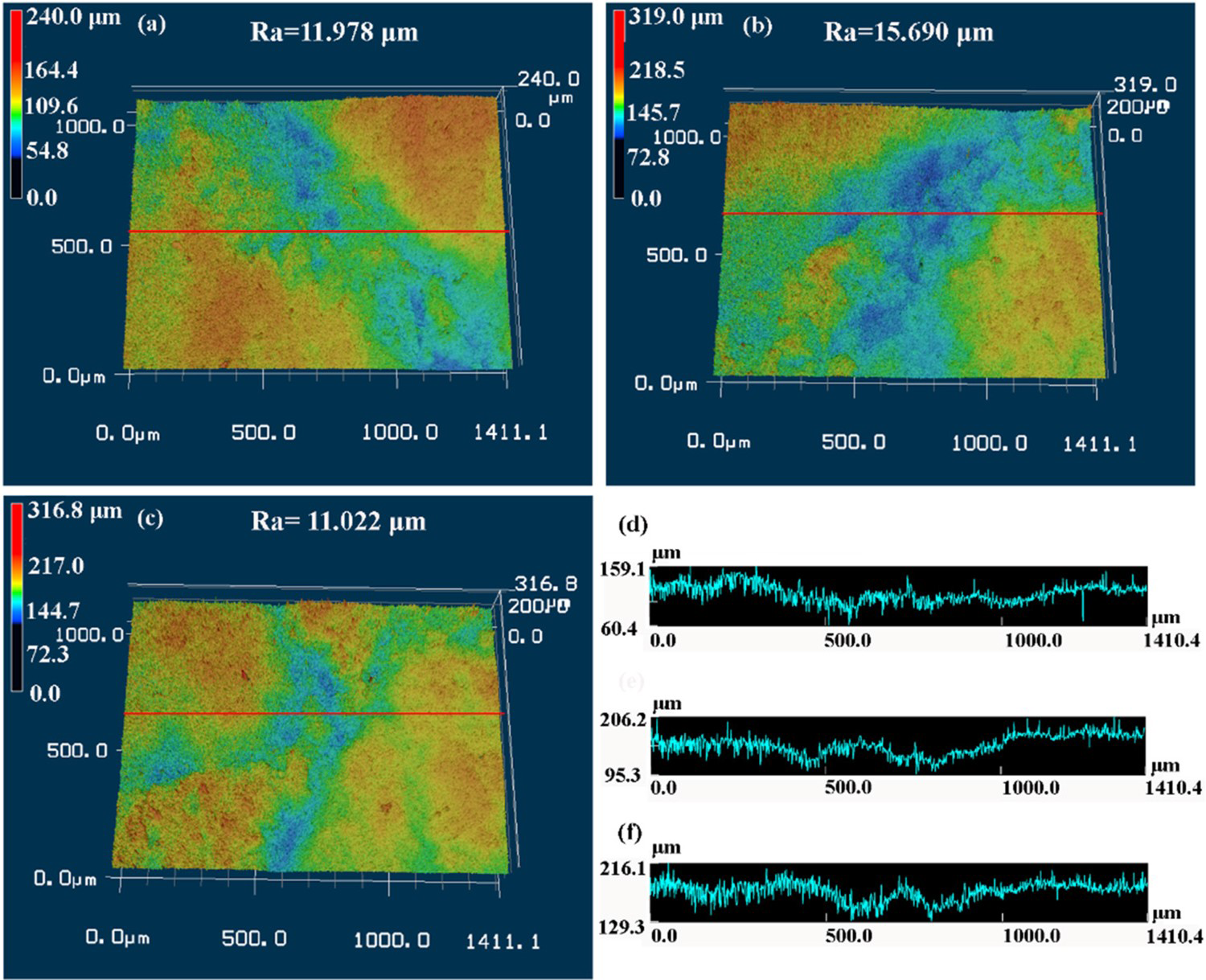
To further disclose the wear behaviour of the Cr15 standard samples under the SiC abrasive, the worn surface characteristics are shown in Figure 12. For 1 kg applied load, numerous embedded SiC abrasives can be found on the worn surface accompanied by the short-range plowing grooves. The deep of the plowing grooves increases with applied load. A continuous plowing with 15 µm width crosses the worn surface of the Cr15 standard sample under the 2 kg applied load. By the way, it can be observed that some fractured SiC abrasives occur in the deep concaves. Compared with 1 kg applied load, the number of fatigue pits increases under the load of 3 kg. Some visible cracks appear in the plowing grooves because of the rolling and cutting action of SiC abrasives. Under a high applied load, the Cr15 surface appears plastic deformation with the roll-over of the SiC abrasives, forming a smooth flat.
SEM micrographs of the Cr15 standard samples after wear (against SiC sand): (a1)(a2) 1 kg; (b1)(b2) 2 kg; (c1)(c2) 3 kg.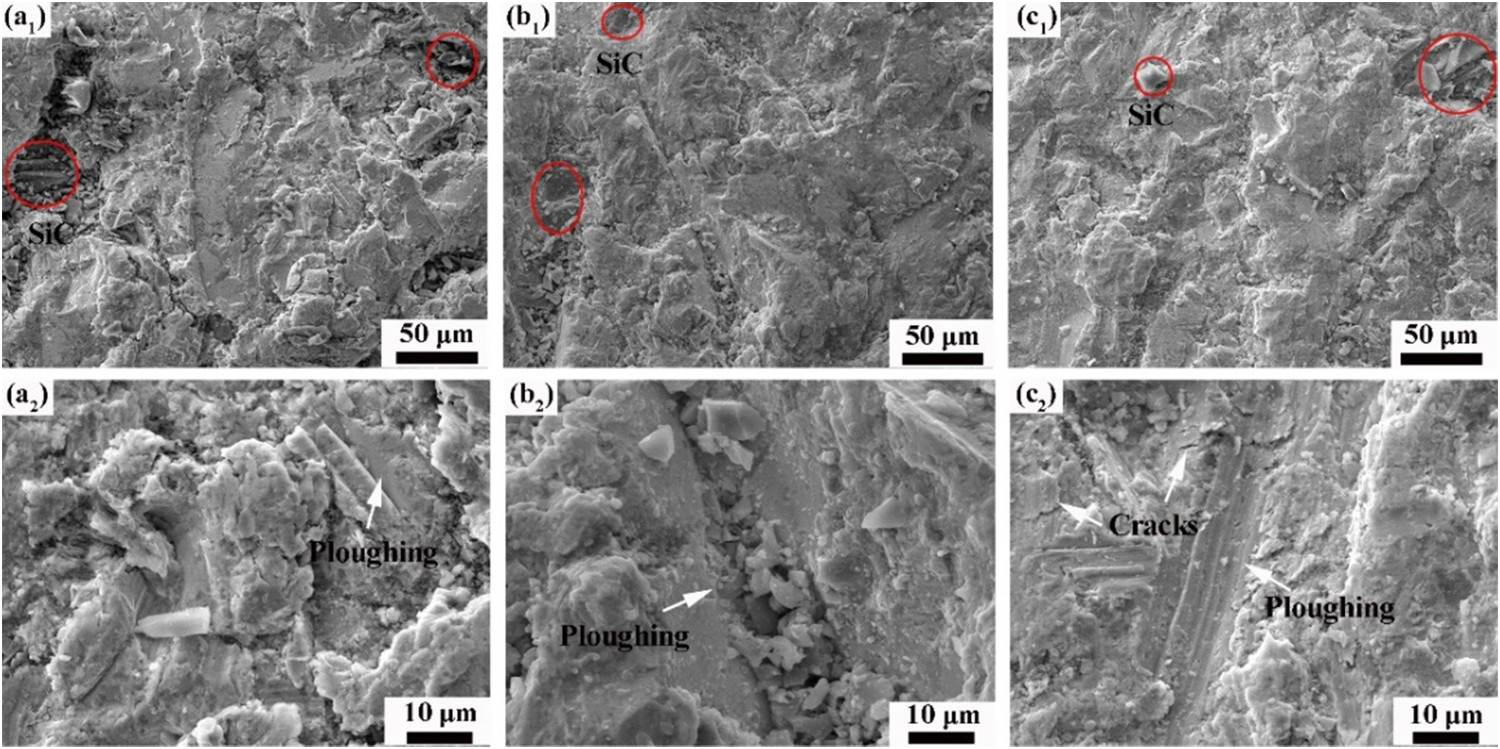
Three-body abrasive wear mechanisms
This work systemically investigated the three-body abrasive wear behaviour of the ZTA/Fe composites under the SiO2 and SiC sands. The wear mechanism schematic of the ZTA/Fe composites was depicted in the Figure 13. Compared with the ZTA ceramic particles, low-hardness SiO2 abrasive preferentially removes the Cr15 matrix, forming protuberant ZTA particles. The extruded ZTA ceramic particles can resist wear force to protect the Cr15 matrix surrounding the ceramics. On the other hand, the Cr15 matrix supports the ZTA ceramic particles due to its excellent plasticity and strength. The wear resistance of the ZTA/Fe composites is superior to the Cr15 standard samples. Additionally, the mass loss of the ZTA/Fe composites increases with applied load. Therefore, the wear mechanism of the ZTA/Fe composites is the cutting and fatiguing wear of the Cr15 matrix and the ‘protecting effect’ of the ZTA ceramic particles. From Figure 13(c), the ZTA ceramic particles and the Cr15 matrix were simultaneously removed due to the high cutting force of the SiC abrasive. The SiC abrasive can cross the worn surface of the ZTA ceramics and the Cr15 matrix. Furthermore, smooth flats appear on the worn surface of the ZTA/Fe composites without visible extruded ZTA ceramic particles. On the SiC abrasives condition, the main wear mechanism of the ZTA/Fe composites is cutting. Based on the high applied load, residual little-size ZTA ceramic particles will peel off during the abrasive wear process. Therefore, the ZTA ceramic particles have ‘negative effect’ on the wear resistance of the ZTA/Fe composites under the SiC abrasive.
Schematic illustration of the three-body abrasive wear process of the ZTA/Fe composites under the SiO2 (b) and SiC (c) abrasives.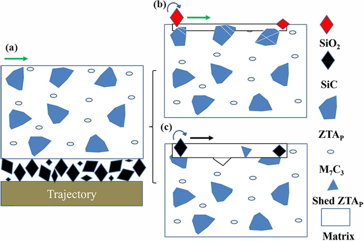
Conclusions
The three-body abrasive wear behaviours and mechanisms of the ZTA/Fe composites were investigated under the SiO2 and SiC sands. The microstructures and topographies of the worn surface of the ZTA/Fe composites and the Cr15 standard samples were characterised. The following conclusions can be drawn:
The ZTA/Fe composites were fabricated utilising infiltration casting. A continuous silicate transition layer connected the Cr15 matrix and the ZTA ceramic particles, which appeared close and tight without visible defects such as cracks, delamination, and holes. The mass loss of the ZTA/Fe composites and the Cr15 standard samples increased with the wear duration and applied load. The introduction of applied load aggravated material removal during the three-body abrasive wear. In the case of SiO2 abrasives, the mass loss of the ZTA/Fe composites was lower than that of the Cr15 standard samples; however, the mass loss of the ZTA/Fe composites was higher than that of the Cr15 standard samples under the SiC abrasives. For SiO2 abrasives, the protuberant ZTA ceramic particles could protect the Cr15 matrix surrounding ceramic particles. The wear mechanism of the ZTA/Fe composites was the cutting and fatiguing wear of the Cr15 matrix and the protecting actions of the ZTA ceramics. However, the ZTA ceramics and the Cr15 matrix together cut dominated during the wear process under the SiC abrasives. The ZTA/Fe composites had an equivalent amount of mass loss for the Cr15 standard samples under the SiC abrasives, which was attributed to the cutting and breaking failure of the ZTA ceramic particles.
Footnotes
Disclosure statement
No potential conflict of interest was reported by the author(s).