
Abstract
In this work, CoCrFeNi and CoCrCuFeNi multi-principal element alloys were welded using an autogenous gas tungsten arc welding process. Tensile testing, microhardness, X-ray diffraction, scanning electron microscopy, electron back scattered diffraction techniques were used to study the mechanical properties, crystal structure and microstructures of the base metals (BMs) and welds. It was found that CoCrFeNi alloy was easily weldable while CoCrCuFeNi alloy produced transverse cracks. Only 13.5% decrease in ultimate tensile strength as compared to its BM was observed in CoCrFeNi alloy. Whereas poor tensile properties were observed in CoCrCuFeNi alloy due to Cu segregation and micro-cracks. Fractography analysis of the BM and weld specimen shows ductile failure in both the alloys.
Keywords
Introduction
Industrial progress is often linked with the development of novel materials with desired properties [1,2]. Since ancient times, metallic alloys have been used for structural applications wherein property enhancement is achieved by adding alloying elements in minor amounts to a principal element (Fe in steel, Ni in superalloy and Al in aluminium alloy). However, adding too many alloying elements to the base element mostly led to the formation of undesired brittle compounds that restricted the further development of new alloy systems [3]. This shortcoming was overcome by multi-principal element alloy (MPEA) alloys that were introduced a few decades ago with equiatomic or near equiatomic composition of five or more elements [4]. Mixing too many elements should lead to the formation of intermetallic compounds, however many MPEA forms simple solid solution phases such as face centred cubic (FCC), body centred cubic (BCC) and hexagonal closed packed or multiple phases consisting of two or more of these phases. A solid solution phase formation in MPEA could be due to high configurational entropy. Besides, there are further parameters like the atomic radius and electronegativity also influence the phase formation in MPEAs [4]. MPEAs have attracted attention of many researchers due to their remarkable mechanical properties, corrosion resistance, wear resistance, irradiation tolerance, fatigue resistance, stability at high and low temperatures [5,6]. Among the MPEAs, CoCrFeNi and CoCrCuFeNi alloys could be used in the nuclear industry due to better irradiation resistance, and in marine application due to their superior corrosion and antifouling properties [7-11]. Therefore, it is important to know the weldability of these HEAs in order to use them as structural materials. Welding plays a key role in the wide acceptance of any material at an industrial scale since different sections can be permanently joined in desired shapes depending upon the application [1]. Higher investment and operation costs of friction stir welding, laser beam welding and electron beam welding discourage industries from using them on a large scale [12]. Most of the published work on MPEAs welding focuses on CoCrFeNiMn MPEA using fusion welding and solid-state welding process [13]. MPEAs were welded without weld defects with the strength similar to that of its base metal (BM) at room and sub-zero temperatures [14,15]. Oliveira et al. have studied the welding behaviour of laser-welded CoCrFeNiMn alloy with 316 stainless steel and found a single FCC phase after welding [16]. A single-phase FCC structure with the ultimate tensile strength of (UTS) of 519 MPa was observed in the gas tungsten arc welding (GTAW) of CoCrFeNiMn alloy [17]. Al0.5CoCrFeNi welded with GTAW produces FCC and BCC phases in weld and has lower BCC phase compared to BM due to rapid cooling. Reduction in BCC phases causes a decline in UTS and hardness [18]. It has been reported that the segregation of Cu during GTAW welding of AlxCoCrFeNiCuy alloy promotes hot cracking [19].
Although GTAW process is the most extensively used process in industry compared to other processes mentioned above, surprisingly limited work has been done on welding MPEA with GTAW process [20]. In this work, for the first time, CoCrFeNi and CoCrCuFeNi MPEA are being welded using the GTAW process. In addition, the microstructural evolution and mechanical properties of the weldments are studied.
Material and experimental procedure
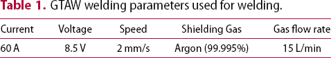
GTAW welding parameters used for welding.
Result and discussion
Micrographs of the CoCrFeNi and CoCrFeNiCu welds are shown in Figure 1. Typical, dendritic, solidification microstructure is observed in both the welds. Good weldability with no defects such as porosity and cracks are observed in CoCrFeNi weld zone (WZ) (Figure 1(a)). However, CoCrCuFeNi alloy's weld shows solidification cracks visible in the weld (Figure 1(b)). Liquidation crack is also present in heat-affected zone (HAZ) as shown in Figure 1(c). Magnified image of WZ crack of CoCrCuFeNi is shown in Figure 1(d). All the crack is in transverse to the welding direction. Many welding trials were carried out; however, cracks were present in CoCrCuFeNi alloy in all the welding conditions. It has also been reported that strong segregation of Cu in the system during welding caused hot cracks in fusion welds in AlxCoCrCuyFeNi alloys [19]. One way of avoiding the cracks is by reducing or avoiding the Cu in the system. The other way is to employ a faster cooling rate as in the case of the laser welding process [22].
(a) CoCrFeNi WZ. (b) Cracks observed in CoCrCuFeNi WZ. (c) Magnified image of crack in HAZ. (d) Magnified image of crack in WZ.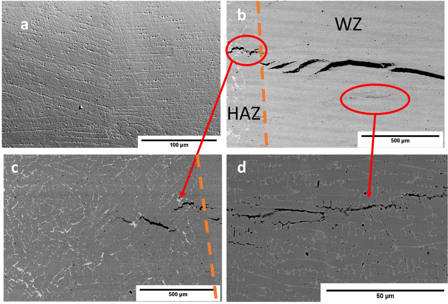
Figure 2 shows the XRD patterns of the BMs and welds. Before and after welding, XRD patterns of both BM and welded samples show a simple FCC solid solution phase. However, the BM and the weld of CoCrFeNiCu alloy show an additional minor FCC peak (hump) due to the presence of Cu segregation shown in Figure 2 marked with an arrow. An additional minor Cu-FCC peak in CoCrFeNiCu alloy was already reported [23,24]. It is clear from Figure 2 that no change in the crystal structure is observed before and after welding.
Shows XRD patterns of base metals and welds of CoCrFeNi and CoCrCuFeNi alloys.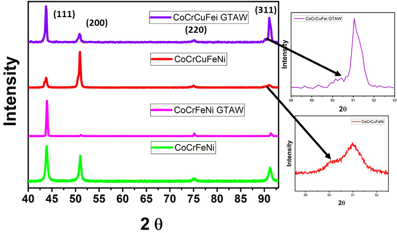
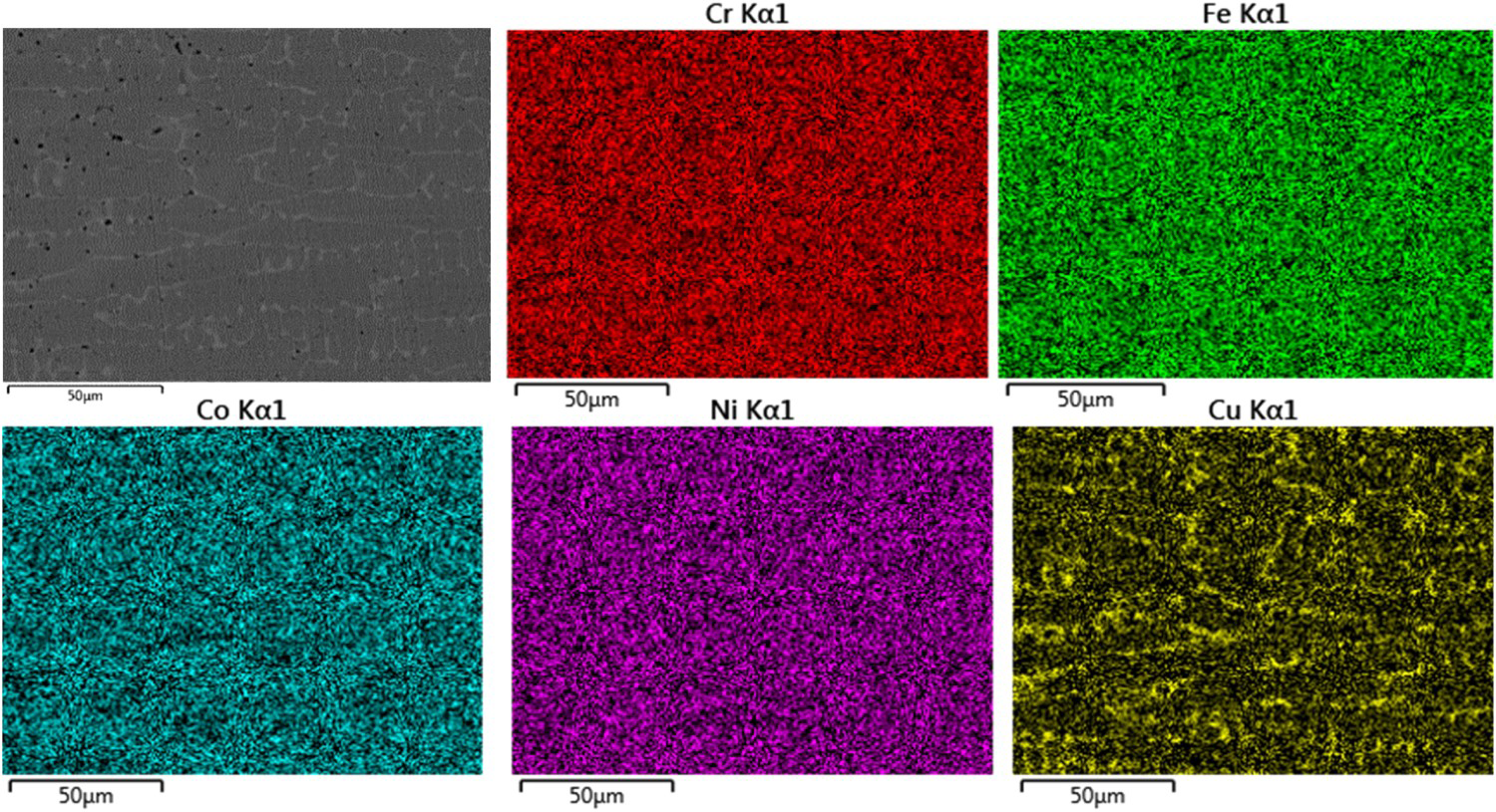
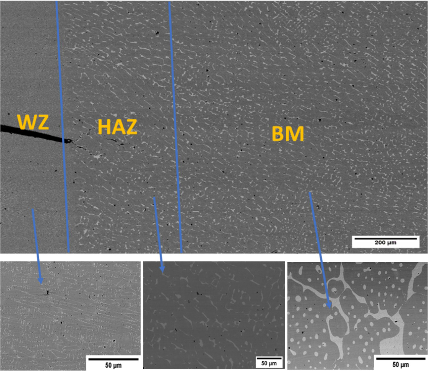
Figure 3 shows the elemental map of the CoCrFeNi alloy weld, which shows equal distribution of the elements in the matrix. On the other hand, segregation of Cu along the grain boundaries is observed in CoCrCuFeNi alloy weld (Figure 4). It has already been reported that Cu segregation at the grain is mainly due to the positive enthalpy of mixing [9]. A narrow HAZ region is also visible in the Figure 5 having small liquidation cracks. However, we could not find any difference in the hardness between the HAZ zone and BM. A separate HAZ could not be identified in welded CoCrFeNi either through micrograph or through hardness measurement. Inability to detect HAZ could be due to homogenisation treatment given to BM causing minimal changes during welding. A similar phenomenon has already been reported by Oliveira et al. [20]. It is also evident that the GTAW process causes decreases in the size of Cu precipitate in WZ in comparison to BM as shown in Figure 5. The decrease in size of Cu precipitate is due to the faster cooling rate associated with the GTAW welding process as compared to casting. Positive mixing enthalpy between Cu and Co, Cr, Fe and Ni (+6, +12, +13 and +4 kJ/mol, respectively) and faster diffusivity rate causes micro-segregation in WZ and HAZ and such effect is consistent with the segregation observed during directional casting by Zeng et al. [25].
Elemental distributions in CoCrFeNi weld. Elemental distributions in CoCrCuFeNi weld. Microstructures showing WZ, HAZ and BM of CoCrCuFeNi alloy.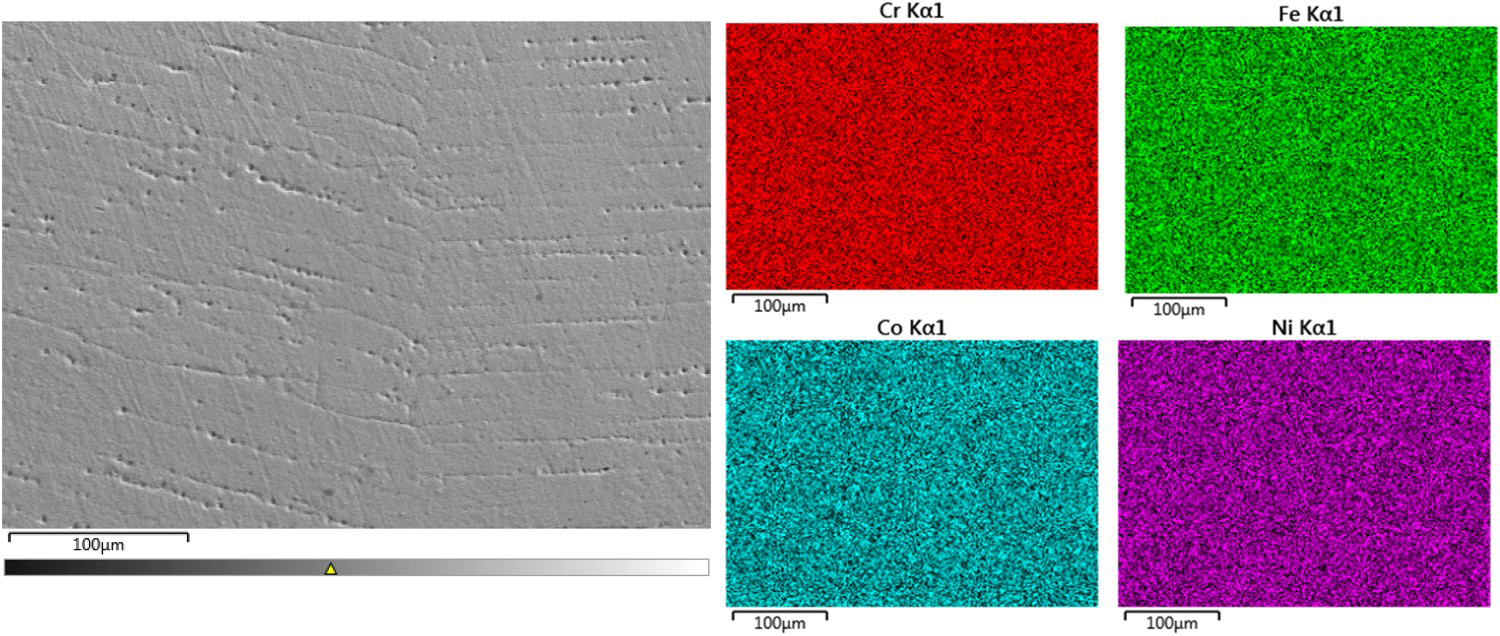
Chemical composition of the BM and Welds in at. %.
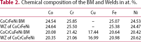
Figure 6(a,b) shows IPF images of WZs of CoCrFeNi and CoCrCuFeNi alloys. IPF images of BM have shown equiaxed grains and twin boundaries in both the BMs [22]. CoCrFeNi BM has an average grain size of 27 μm while BM of CoCrCuFeNi has 6 μm grain size. Addition of Cu in BM reduces the grain size also ∑3 twin boundary in the BM of CoCrFeNi and CoCrFeNiCu alloys is 61% and 25%, respectively. Reduction in ∑3 twin boundary in CoCrCuFeNi BM is due to increase in stacking fault energy and decrease in grain size [28,29]. However, after welding, average grain size of CoCrFeNi (Figure 6(a)) and CoCrCuFeNi (Figure 6(b)) alloys are increased to 36 and 25 μm, respectively. Transverse cracks (Figure 6(b)) are observed in CoCrCuFeNi alloy weld despite having smaller grains as compared to CoCrFeNi alloy weld.
IPF image of (a) WZ of CoCrFeNi, (b) WZ of CoCrCuFeNi.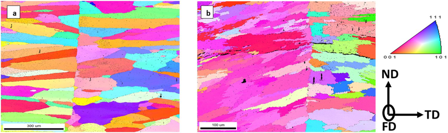
Figure 7 shows inverse pole figures of WZ of CoCrFeNi and CoCrFeNiCu alloys. CoCrFeNi BM shows weak fibre texture in <335> parallel to ND [22]. However, after welding this texture is changed to <115> parallel to ND shown in Figure 7(a). Similarly, a weak fibre texture is observed in <116> parallel to ND in BM of CoCrCuFeNi [22] while post-welding fibre texture shifted to <113> parallel to ND as shown in Figure 7(b). Generally, texture has a strong influence on mechanical properties, but it is expected that the presence of weak texture in both BMs and welds will not have a significant influence on the mechanical properties.
Inverse pole figure (a) CoCrFeNi weld, (b) CoCrCuFeNi weld.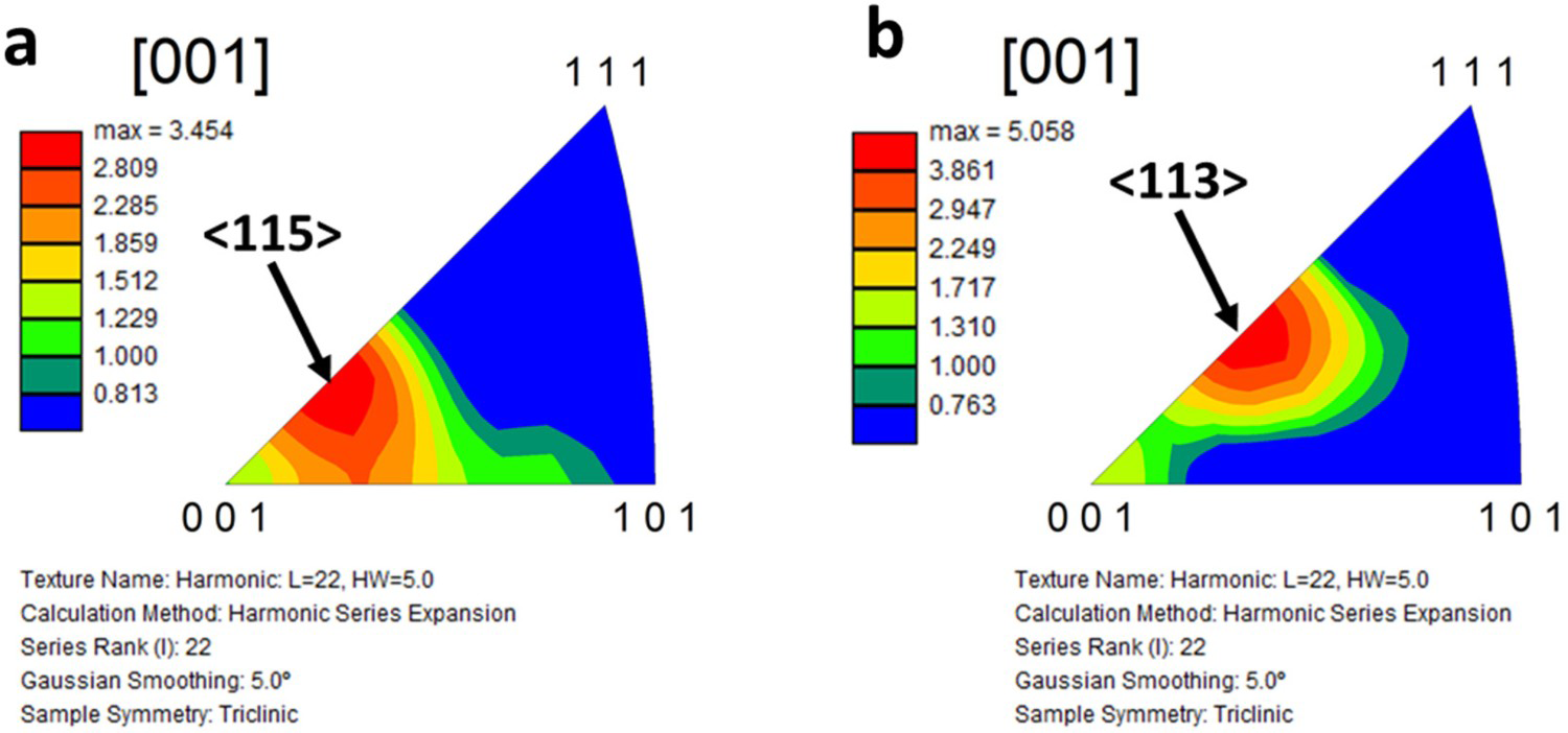
Stress–strain curves of the BMs and welds obtained from tensile testing are shown in Figure 8. UTS, yield strength (YS) and % elongation (% E) of CoCrFeNi alloy in the BM condition is 593, 370 MPa and ≈70%, respectively. While the UTS, YS and % E of CoCrFeNiCu BM is 666, 331 MPa and ≈90%, respectively. Similarly, microhardness value of CoCrFeNi BM (153 ± 2 HV) is lower than that of CoCrFeNiCu alloy (177 ± 3 HV). The higher hardness and strength are observed in CoCrFeNiCu BM could be due to the smaller grain size that induces Hall–Petch strengthening. Moreover, the addition of Cu will increase the lattice strain that would further improve the strengthening [30]. Only a marginal reduction in UTS (512 MPa), YS (270 MPa) and % E (≈50%) are observed in welded CoCrFeNi alloy as compared to its BM. However, CoCrFeNiCu alloy weld failed well below that of BM YS. From the fractured specimens, it was observed that both CoCrCuFeNi and CoCrFeNi alloys’ welds failed in the WZ. Although, tensile test specimens of CoCrCuFeNi alloy were prepared from the crack-free region of WZ and HAZ but unable to avoid micro-cracks in the weld and HAZ which clearly reflects on the lower value of UTS (50 MPa).
Engineering stress vs. engineering strain curves of BM and Welded specimen of CoCrFeNi and CoCrCuFeNi.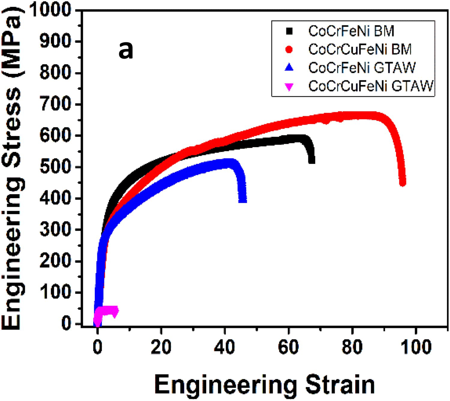
Fracture analysis
Figure 9 shows cross-sectional view of broken welded specimens (fracture surface). CoCrFeNi and CoCrCuFeNi BMs having coarse dimples [22]. Fractured surface of welded CoCrFeNi (Figure 9(a)) shows finer dimples in comparison to unwelded specimen. Dimples feature signifies ductile failure due to large plastic deformation inducing microvoid nucleation and coalescence [31,32]. In contrast, cleavage fracture is observed in CoCrFeNiCu WM (Figure 9(b)) which is confirmed by the river-like pattern and cleavage step. Welding in Cu containing MPEA causes micro-crack formation in WZ and HAZ which act as nuclei for cleavage fracture. Cleavage fracture is further characterised by its occurrence at low stresses [33,34]. Due to the difference in the thermal expansion coefficient of Cu with other element, CoCrCuFeNi cannot withstand the stresses produced during welding which results in crack initiation [19].
Fractured surface of (a) weld zone of CoCrFeNi, (b) weld zone of CoCrCuFeNi.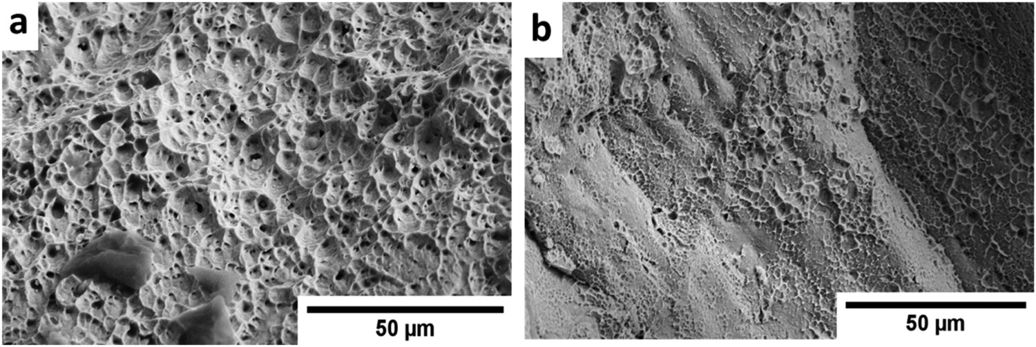
Conclusion
In this study, weldability of CoCrFeNi and CoCrCuFeNi MPEAs using an autogenous GTAW process is studied through microstructural and mechanical characterisations. The following observations are made from this work. A single-phase FCC structure was observed in CoCrFeNi BM and WZ while two FCC phases were observed in CoCrCuFeNi BM and WZ. The second FCC phase is from segregated Cu. The addition of Cu causes a reduction in grain size and an increase in lattice strain. Therefore, increase in UTS (from 593 to 666 MPa) is observed in CoCrFeNiCu alloy. CoCrFeNi alloy is easily weldable without any cracks. Whereas CoCrCuFeNi alloy has shown transverse cracks along the welding direction in WZ and HAZ. CoCrFeNi alloy after welding shows a slight decrease in UTS (512 MPa). Whereas a huge reduction in UTS is observed in CoCrCuFeNi alloy's weld.
Footnotes
Acknowledgements
We are very thankful to Dr. C. P. Ramanarayanan, Vice-Chancellor, DIAT (DU) for constant support. This work was supported by Science & Engineering Research Board, Department of Science & Technology (DST), India (No: EEQ/2017/000724). We are grateful to the Director, DMRL, Hyderabad for supporting miniature tensile tests.
Disclosure statement
No potential conflict of interest was reported by the author(s).