






Abstract
The influence of deep cryogenic treatment (DCT) on carbides precipitation and isothermal softening behaviour as a function of both temperature and time during tempering of H13 steel was investigated. The results show that the retained austenite transformed into martensite leading to an increase in hardness. The carbon content of martensite decreased after DCT and tempering according to the calculation of the X-ray diffraction spectrum. This indicates that more fine carbides precipitated from the martensitic matrix after DCT. The morphology of microstructure and distribution of carbides have verified the properties improvement mainly depending on the retained austenite transformation and more fine carbides precipitated after tempering. In addition, the carbides precipitating and coarsening are the main causes of thermal softening.
Introduction
Hot work tools are the most significant tool which makes the hot or liquid metals to a specific shape and required dimensions production such as high pressure die casting, hot forging and hot extrusion processes. As a main forming tool for hot metals in modern industry, the tools required excellent mechanical properties such as higher hardness, toughness and microstructural stability because of the harsh working conditions, as well as the pursuit of increasing service life. In especial, energy conservation and environmental protection are facing severe challenges in the contemporary manufacturing industries. A large amount of waste heat will be generated in the process of casting and forging, and a large amount of material waste will be generated in the process of cutting in the traditional mould industries. As is known, the manufacturing dies to get exposed to harsh cyclic loading and rapid cooling and heating at elevated temperatures often leading to corrosion, abrasion and thermal fatigue during service [1]. These properties of hot work tool steels result from both their chemical composition and microstructures formed during heat treatment. For instance, extrusion tools exhibit a strain-time pattern under a variety of cyclic loading conditions and thus the dies are prone to failure by fatigue [2]. In addition, the thermal stability of the tools was another important property because of the elevated working temperature. As regards the service life, the hot forming dies involved a series of failure mechanisms due to extreme working conditions. Although it is inevitably replaced after a period of service time, the die costs including materials and heat treatments, labour and time costs account for about 30% of the total costs for a closed die forging process [3].
Deep cryogenic treatment (DCT) is a supplementary process of traditional heat treatment performed on steel soaking or cooling into liquid nitrogen temperature (−196°C) to improve performance in service. Authors [4] have pointed out that DCT is serviced by many small companies to increase the service life of steel products, such as drills, cutters, gears, punch dies, tool bits, etc. This treatment can be traced back to the Swiss watch-makers who stabilised the delicate components by storing them for several years in snow mountain caves to obtain maximum performance and precision before a century [5]. It has been reported that the cold treatment of steel could improve its performance of steel, such as wear resistance, fatigue, dimensional accuracy, etc. [6]. Moreover, the deep cryogenic cycling treatment is therefore believed to be an effective, feasible and non-destructive way to rejuvenate and plasticise metallic glass [7]. Previously published literature has reported that the tool life was improved by 44–126% [8] and demonstrated 39–68% [9] improvements in wear rate on D6 tool steel after DCT. Çiçek et al. [10,11] have investigated the performance of tungsten carbide end mills in the machining of AISI H13 hot work tool steel under dry and wet conditions. They found that the cryogenic treatment was also effective in decreasing resultant cutting force (Fc) and average surface roughness (Ra) as well as the tool life was improved by 126.1%. Kara et al. [12] have investigated the performance of the grinding parameters used in the cylindrical grinding process of cryogenically treated AISI 5140 steel and the results showed that optimal average surface roughness values were obtained on specimens cryogenically treated for 30 h. Therefore, a comprehensive understanding of the microstructure evolution of hot work tool steels during DCT is significant.
The benefits of the applications subjected to DCTs on tool steel are an enhancement of the dimensional stability and service life of the tools due to the decrease of retained austenite content. Li et al. [13] analysed the distortion mechanism of a cold work tool steel during quenching and DCT and pointed out that the inhomogeneous distribution of volumetric strain in specimen brings about the distortion due to the asynchronism of phase transformation. Meng et al. [14] have reported that the difference in retained austenite content of AISI D2 and 52100 steel after DCT and cold treatment is negligible though the improvement in wear resistance. They have concluded that rather than the removal of retained austenite, improvement in wear resistance by DCT over cold treatment is due to preferential precipitation of fine η-carbides by the DCT. Authors [5] have pointed out that a uniformly dispersed network of fine carbide and a homogenised microstructure are the main reasons for the properties improvement of tool steel. In addition, researchers also have evidenced an increase in the compressive residual stress in steel which is subjected to DCT before tempering [15]. The results show that the samples subjected to DCT have undergone a reduction in compressive residual stress after tempering [16]. Baldissera and Delprete [17] have concluded that the improvement obtained by DCT is mainly contributed to the complete elimination of retained austenite and the formation of very small carbides dispersed in the tempered martensitic structure. However, the authors [18,19] have suggested that the martensitic transformation at low temperatures is accompanied by plastic deformation of virgin martensite formation. The plastic deformation causes the partial dissolution of carbide particles and the immobile carbon atoms were captured by gliding dislocations and the formation of carbon clusters that can serve as sites for nucleation of fine carbide particles during subsequent tempering. Li et al. [20,21] proposed that the interstitial carbon atoms can also migrate to the defects such as dislocations or martensite/austenite interfaces due to the lattice shrinking strain energy at cryogenic temperature. On subsequent tempering, these interstitial carbon atoms act as nuclei for the formation of fine carbide particles near dislocations.
Çiçek et al. [22] have investigated the effect of cryogenic treatment on the machinability of H13 tool steel and pointed out that the samples subjected to DCT exhibit a reduction in wear rate, surface roughness and cutting forces during the turning of this steel. This indicates that the service life is enhanced after the DCT of H13 tool steel. Koneshlou et al. [23] have reported the improvement in hardness, tensile strength, impact energy and wear resistance when the sample was treated by DCT. The improvement in these properties was explained by the transformation of retained austenite to martensite, precipitation of very fine carbides and a more uniform & smaller martensitic lath microstructure. However, most of the conclusions are not cogent enough yet because of the absence of direct evidence. The reason is the samples were subjected to a conventional tempering process before the microstructure analysis and mechanical testing. It is not adequate to completely clarify the influence of DCT on the microstructure changes and mechanical improvement. Therefore, this paper focuses on the effects of DCT on microstructure evolution and isothermal softening behaviour during temping in order to make clear the mechanisms of tool steel after DCT.
Experimental procedures
Materials and treatments
The chemical compositions of the AISI H13 tool steel (wt-%).

The detailed heat treatments of the tested steel.

Mechanical and microstructure investigations
To provide a systematic investigation of the possible underlying mechanism of DCT in H13 steel. The hardness of the samples was determined through the Rockwell hardness tester under a load of 150 kg for all samples. Each effective value of the hardness was the average hardness of at least seven points for a duration of 30 s and the depth of resistance to indentation was automatically recorded on the dialgauge. The Charpy V-notch samples (10 mm × 10 mm × 55 mm) were machined from the supplied bars and used for impact tests with an impact absorption energy pendulum of 150 J. The microstructure and phase distribution was characterised by a scanning electron microscope (SEM, MLA-650). The samples were afterward also inspected after being etched for 5–10 s with 5% nital acid alcohol. The Philips X-ray diffraction instrument using Cu Kα (λ = 1.5418 × 10⁻¹⁰ m) X-ray source was applied to determine the volume fraction of retained austenite with a scanning step of 0.03° per second. For the microstructural characterisation (bright and dark-field imaging) and the analysis of selected electron diffraction patterns, transmission electron microscopy(TEM, JEM-2100) operating at 200 kV accelerating voltage was employed.
Tempering kinetics law
The tempering kinetics due to solid phase transformation controlled by atoms diffusion were proposed by the Johnson–Mehl–Avrami (JMA) [24-26]) as presented in Equation (1):


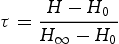
The tempering ratio τ is defined as the variation of hardness during temperature by Equation (3). Here H0 is the quenched hardness, H∞ is the annealed hardness and H is the intermediate hardness.

Results
Microstructure characterisations after DCT
The optical microstructure of the quenched and DCT treated samples are shown in Figure 1. Figure 1(a) shows a typical martensitic microstructure of conventionally heat-treated H13 steel with no primary carbides can be observed at the prior austenite grain boundaries. In general, the undissolved carbides are not allowed to exist in the quenched sample as far as possible according to the requirements of dies. The samples were soaked into liquid nitrogen (−196°C) for involving DCT and the microstructure of the DCT treated sample was presented in Figure 1(b). as shown in the microstructure, a similar microstructure is observed with no additional carbides precipitated from the martensitic matrix.
Optical microstructure of the steel after different treatments: (a) after quenching and (b) after DCT.
The DCT was carried out after quenching to clarify the effects of DCT on microstructure, as shown in Figure 2. To compare the microstructure of the quenched and DCT treated samples analysed by SEM, the microstructure consists of martensite laths. The original austenite grain was segmented by several martensitic beams during martensite transformation. However, the edges of martensite laths are clearer and the size of martensite laths becomes smaller after DCT. According to the microstructural evolution of the samples subjected to different treatments, the martensitic laths have become finer when the sample carried out DCT treatment (Figure 2(b)). The formation of finer martensite laths and the precipitated carbides is even more distinct when the samples are subjected to DCT after tempering, see Figure 2(c, d).
SEM micrograph of the martensite laths after different treatments: (a) after quenching; (b) after DCT; (c) tempering after quenching and (d) tempering after DCT.
The authors [27] have claimed that the grain size of the weld zone was decreased to a certain degree after DCT. In addition, Barron [28] has also claimed that the improvement of wear resistance after DCT presented some relationship to grain refinement besides the retained austenite transformation. Hu et al. [29] have reported that DCT is an effective way to refine the amount of retained austenite in super bainitic steels. Moreover, DCT increased the hardness and stability of the microstructure according to the study of the super bainitic steels. Koneshlou et al. [23] also have suggested that DCT led to smaller and more uniform martensite laths. In prior works, Li et al. [21] have suggested that the DCT promotes the energy of martensite transformation and increases its instability because of the lattices’ contraction intensely during cooling to cryogenic temperature continuously. As a result, the refinement of martensite laths plays a very important role in terms of performance and dimensional stability and wear resistance of the tool steel in the service.
Hardness variation before and after DCT
The hardness values of the specimens after quenching and after DCT are presented in Figure 3. To obtain more accurate experimental data, at least seven samples were tested in this experiment and the effective hardness value was acquired from the average of five measurements for each sample. The effects of DCT are considered to be a significant improvement in the hardness of the steel as is shown in Figure 3. The hardness of the DCT treated samples are considerably higher than that carried out quenching treatment. According to the results, the averaged hardness is enhanced at least 3HRC after DCT compare to the quenched samples.
Hardness variation of the samples before and after DCT.
Numerous investigators have covered that the hardness of tool/die steels is increased after DCT in previous research. For instance, Zhirafar et al. [30] have reported that the improvement of hardness by DCT exceeds conventional heat treatment between 3.1% and 1.6% relying on the aging temperature for 4340 steel. Yan et al. [31] have pointed out that the hardness of W9Mo3Cr4V high-speed steel was improved by DCT as compared to conventional heat treatment. Li et al. [32] have reported that the hardness of cold work steels was enhanced after DCT. All of the above suggested that the mechanism of hardness improvement was attributed to the transformation of retained austenite into martensite during the treatment of the samples cooling to a lower temperature. In addition, the parameters of DCT such as holding times and cooling rate and so on also have a significant influence on hardness according to the ref. [33]. Authors [32] also have suggested that the hardness was increased with the prolonging time during DCT in liquid nitrogen. The application of longer DCT times significantly improved wear resistance and improved the hardness slightly (1–3 HRC) [34]. The results show from Figure 3 that the hardness of the sample increases by 3 HRC after DCT. This indicated that DCT is an effective process to improve the properties based on traditional heat treatment.
The hardness variations during tempering at different temperatures for 0∼10 h are plotted in Figure 4. The hardness decreases continuously with the elevated tempering temperatures either in the quenched samples or the samples subjected to DCT. However, as is shown in Figure 4(a), the hardness of quenched samples decreases to 40 HRC, 38 HRC, 35 HRC and 32 HRC at tempering temperatures of 600, 620, 650 and 680°C for 10 h respectively. While the hardness of samples after DCT is 46 HRC, 44 HRC, 40 HRCand 38 HRC under the same conditions, as illustrated in Figure 4(b). The hardness of the DCT treated samples is 6 HRC higher than that of conventional heat-treated samples even though the samples were tempered at 680°C for 10 h. This indicates that the stability of the steel has been enhanced after DCT.
The hardness variations during tempering at different temperatures: (a) after quenching and (b) after DCT.
Effects of DCT on the mechanical properties
Statharas et al. [35] have pointed out that the most common failure mechanism of tool/dies steel components like chipping, galling and cracking. is controlled by impact toughness. Impact toughness is an important property of tools because the service life of the tools is dependent not only on their wear resistance but also on their impact toughness. Therefore, the impact toughness of tool steel subjected to DCT and conventional heat treatment is not only of scientific interest but also of immense technological importance for the tools. The hardness and impact toughness data subjected to conventional heat treatment and DCT after tempering are shown in Figure 5. The hardness is plotted on the left primary Y-axis and the impact toughness on the right secondary Y-axis. As shown in Figure 5, the tempered hardness of the DCT treated samples shows an improvement compare to the conventional heat treatment. However, the relationship between hardness and toughness of the steel is usually inversely proportional. Although the earlier reports have related the influence of sub-zero treatments on the toughness of tool/die steels [36]. Das et al. [37] have pointed out that the explanations rendered by different investigators are incoherent and systematically investigate the toughness of steel specimens subjected to different types of sub-zero treatments keeping other processing variables related to the pre-history of the materials as invariant.
The mechanical properties after different treatments.
Figure 6 reveals the morphologies of the impact fracture after different heat treatment processes by SEM. The fractography in Figure 6 reveals the regions of cleavage fracture and quasi-cleavage fracture indicating that the main type of fracture is a brittle fracture. However, as shown in Figure 6(b, c), the regions of cleavage fracture increased after DCT. No cracking of secondary carbide particles has been observed in the fracture surfaces of any specimens. The authors [37,38] have suggested that the formation of microvoids by decohesion of secondary carbides is quite common in the fracture process for the tool/die steels. In addition, Kwon [39] has claimed that the void nucleation of interfacial decohesion for carbide particles in steels is based on the dislocation pile-up model. That is the void was be formed when the local interfacial stress around the particle reaches a critical interfacial strength. This indicates that the carbide particles increased the regions of cleavage fracture and it is proved that the analyses are consistent with these results by testing and measuring, as shown in Figure 6.
Fracture morphology of the steel after different treatments: (a) tempering after quenching; (b) DCT after tempering; and (c) tempering after DCT.
Discussion
Phases analysis after different heat treatments
The X-ray diffraction technique was used for phase analysis after different heat treatments including the content of martensite calculation and the volume of retained austenite determining. The X-ray patterns of the samples after different heat treatments are presented in Figure 7. According to the obtained results, the diffraction peaks of the retained austenite are invisible for all the samples whether the sample was subjected to DCT or not. This indicates that the austenite of all samples is almost completely transformed into martensite during the quenching process. It is difficult to detect retained austenite by X-ray diffraction.
X-ray diffraction patterns of the samples after different heat treatments.
To verify the retained austenite in the steel before and after DCT, TEM was used to determine the morphology of microstructure and phases analysis. Figure 8 shows the morphology of the retained austenite of the steel after quenching. The width of the retained austenite is about 130 nm after quenching. Although the diffraction peaks of the retained austenite are invisible based on the X-ray diffraction analysis from Figure 7, the microstructure of the quenched sample mainly comprised martensite laths and little retained austenite according to the analysis of selected electron diffraction patterns. As is well known, retained austenite is a soft and unstable phase at room temperature. the retained austenite is always presented after traditional heat treatment in high alloy steels. Although it was suggested that the retained austenite is beneficial to the mechanical properties such as impact toughness [40] and the retained austenite can act as a crack barrier phase during the propagation and alleviate the stress concentration at the crack tip in the service [17,41]. However, the retained austenite could transform into fresh martensite during service under cycle stress and/or elevated temperature then cooling down, which causes a series of negative effects on the service life of tools such as dimension and stabilities. The transformation of retained austenite to martensite causes volume expansion resulting in distortion of the tools and then leading to a detrimental effect on the final stage of fatigue. Thus, The elimination of retained austenite after conventional heat treatment is very important for the stability of tool dimension and thermal fatigue performance, especially for the manufacture of high-precision parts in modern industry. Generally, as the authors [42] pointed out that the retained austenite will transform into martensite as long as the transformation of free energy of retained austenite reached a critical value. As is well known, the change of free energy accompanies the martensite formation at the Ms temperature of steels during cooling.
The morphology of retained austenite and selected electron diffraction after quenching.
DCT is a complementary treatment that satisfies the requirements of free energy change exactly during martensite transformation. The researchers have pointed out that the retained austenite could transform into martensite completely after DCT due to the temperature being lower than the martensite finish temperature [43,44]. However, in our experimental results, the microstructure of the sample after DCT contains the retained austenite with thin-film morphology which was identified by selected electron diffraction of TEM, as presented in Figure 9. A large amount of the retained austenite transformed into martensite and the width of the remaining retained austenite is 39 nm after DCT. This experimental result demonstrated that DCT cannot eliminate the retained austenite absolutely rather than promote a great amount of retained austenite to transform into martensite even if the samples were soaked in liquid nitrogen for a long time. Li et al. [20] have pointed out that the carbon atoms will diffuse from martensite to the interfaces of martensite and austenite and then segregate at the interface of martensite/austenite due to the lattice shrinking strain energy at cryogenic temperature. Thus, the thin-film retained austenite between the martensite laths becomes more stable because of the separation of carbon atoms and the retained austenite was reserved during subsequent recovery to room temperature due to carbon enrichment. This is the main reason that the retained austenite within-film morphology exists after DCT as a nano-film characterisation between martensite laths.
The morphology of retained austenite and selected electron diffraction after DCT.
Anisothermal tempering kinetic model
To investigate the influence of DCT on the hardness variation of the experimental steel during the tempering process, the hardness variation of the steel tempered at 560°C for different holding time (0∼20 h) after quenching and after DCT were obtained, as plotted in Figure 10. According to the prior results shown in Figure 3, the hardness was enhanced by 3 HRC after DCT compared with the quenched samples. Although the hardness was reduced both in quenched and deep cryogenic treated samples after tempering, the hardness in the cryogenically treated sample was always higher than the quenched samples during tempering even though the samples were tempered at 560°C for 20 h. According to the obtained results in Figure 10, the hardness values of the DCT samples and quenched samples gradually reduce with the tempering time prolonging. The hardness intervals of the DCT samples and quenched samples keep at about 3 HRC when the tempering time was less than 6 h. However, the hardness intervals increase to 5 HRC when the samples were tempered at 560°C over 6 h. This indicates that it exhibits good hardness stability of the sample after DCT during aging.
The hardness variation of the specimens tempered at 560°C for different time (0∼20 h) after quenching and after DCT respectively.
The tempering of martensitic steels involves the segregation of carbon, the precipitation of carbides, the decomposition of retained austenite and the recovery and recrystallisation of the martensitic structure [45]. The thermal stability of hot working tool steel is generally considered to depend on the degree of decomposition of a solid solution of steel and the amount of carbide precipitation, as well as the segregating and coarsening of alloy compounds in the process of tempering at high temperature. Therefore, the hardness decreases continuously with the extension of heating and holding time during tempering. Thus, the microstructure evolution is a diffusion-controlled process involving the segregation of carbon, the precipitation and coarsening of carbides during tempering.
As is well known, softening was usually assessed by the loss of hardness measured at room temperature between a freshly heat-treated sample and the same sample after 50 h service in the range of 520–600°C. Delagnes et al. [46] demonstrated that softening is the result of the combination of thermal and mechanical effects, and increasing the initial hardness can reduce the cyclic softening rate and improve the fatigue life in the service. DCT enhanced the initial hardness of the steel under the same heat treatment conditions, as shown in Figure 10. According to the results mentioned above, the cyclic softening rate would be reduced and fatigue life would be improved after DCT.
To analyse the softening behaviours of the steel after quenching and DCT, Equations (1) and (3) can be changed as follow:
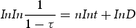
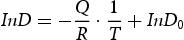
After fitting the JMA tempering kinetic law parameters according to Equations (5) and (6), as shown in Figures 11 and 12. The activation energy during tempering of the quenched samples and the samples subjected to DCT is 379.14 and 407.75 kJ mol−1 respectively. The fitted values for Avrami exponent n at different temperatures 600, 620, 650 and 680°C of the quenched samples were 0.63, 0.43, 0.33 and 0.27, respectively. While the fitted values for Avrami exponent n at different temperatures 600, 620, 650 and 680°C of the samples subjected to DCT were 0.53, 0.38, 0.25 and 0.16 respectively. The values of n reveal the growth mechanism in the coarsening of spheroids and the effects of precipitation on dislocations. According to obtained results, the Avrami exponent n of the tempered samples subjected to DCT is lower than the quenched samples tempering at different temperatures. This indicates that the coarsening rate of spheroids in the steel was reduced when the samples were subjected to DCT. This indicates that the coarsening speed of carbides precipitation from the martensite matrix is small when the samples are subjected to DCT. Li et al. [47] have pointed out that the carbon atoms were segregated near the dislocation or twin crystal boundaries due to the lattice shrinking at liquid nitrogen temperature. Thus, the carbide nucleation positions and nucleation rate increased because of the carbon atoms segregation, resulting in smaller carbides precipitated when the samples carried out tempering.
Plot of lnD versus 1000/T for the calculation of activation energy of different treatments during tempering at 600, 620,650 and 680°C. Plot of ln ln(1/(1–τ)) versus lnt for the calculation of Avrami exponent n of during tempering at 600, 620, 650 and 680°C: (a) after quenching and (b) after DCT.

Microstructure characterisation during tempering
Although it is not difficult to understand the enhanced hardness can be attributed to the transformation of retained austenite to martensite during DCT according to the available results in the literature [23,48]. It shows that the hardness of the DCT samples and quenched samples are different variations during tempering. The different hardness variation of the samples subjected to DCT indicates different characterisation of microstructural evolution during tempering. The microstructure morphology of the samples tempered at 560°C for 20 h after quenching (Figure 13(a)) and after DCT (Figure 13(b)) were analysed by SEM. As illustrated in Figure 13, the microstructure consists of typical plate martensite and several carbides. However, the microstructure of the samples subjected to different treatments displays incongruity in detailed morphology. As we know, martensitic steels involve several stages including carbon segregation, carbides precipitation, retained austenite decomposition, as well as recovery, and recrystallisation during temperature [49]. Although a large number of carbides precipitated from the matrix of the quenched and DCT treated samples during tempering, it shows the different morphology of the carbides after different treatments. Figure 13(a) shows the carbides distribution of the quenched sample after tempering at 560°C for 20 h. Two types of secondary carbides are classified here as large and small secondary carbides based on their size distribution. Compare the number of large carbides and small carbides in Figure 13, it reveals a high population density of large carbides in the quenched sample after tempering at 560°C for 20 h, as shown in Figure 13(a). However, it presents a low population density of large carbides in the sample tempered at 560°C for 20 h after DCT (Figure 13(b)). This indicates that the carbides in the sample which is not subjected to DCT are more easily coarsened during tempering. However, the carbides in the DCT sample are resulted in homogeneous distribution after tempering, as given in Figure 13(b). Das et al. [50] have pointed out that the alteration of carbides volume fraction occurs after DCT due to lowering or removal of retained austenite, resulting in a higher amount of martensite and leading to the formation of more amount of tempered martensite which assists in precipitation of higher amount of secondary carbides during tempering. The homogeneous distribution of fine carbides precipitated from the martensite matrix during tempering resulted in higher stability of hardness. However, the carbides in the quenched sample are easier to coarsen during tempering leading to a decrease in hardness according to the obtained results.
The microstructure morphology of the samples tempered at 560°C for 20 h: (a) after quenching and (b) after DCT.
For investigating the types of precipitated carbides in the quenched and DCT samples after tempering, TEM was used to identify the carbides in detail. Figures 14 and 15 demonstrate the TEM micrograph of the precipitated carbides of the before and after DCT samples tempered at 560°C for 20 h respectively. According to the obtained results, a large number of fine carbides precipitated from the martensite matrix, and the carbides distributed homogeneously relatively after DCT, as presented in Figure 15. However, the carbides precipitated from the quenched sample distributed not as homogenous compared with the DCT sample. Moreover, the carbides are distinctly coarsened during tempering in the quenched sample, as shown in Figure 14. Authors [9,51] have suggested that the volume fraction of carbides increases and the carbides distribution is changed after DCT. Some speculative theories have been proposed to explain the increase of carbides after DCT during tempering. The most accepted theory claims that the volume fraction of carbides increases due to the effects of lattice constriction at low temperature and the carbides were formed during tempering. That is the carbon atoms migrate to neighbour dislocations at low temperatures under the contraction stress and act as beneficial nucleation sites for carbide formation during tempering [52]. Li et al. [20] have suggested that the carbon atoms are easier to segregate nearby the dislocations under the lattice shrinking energy and the defect energy promotes the formation of the fine carbide during tempering through internal friction. Although the internal friction is an indirect method to reveal the mechanism of DCT, it is very sensitive to the carbon atoms and the interactions between carbon atoms and dislocations [53]. According to Cottrell and Bilby [54], interstitial atoms such as carbon atoms can diffuse towards the stress field of dislocations. As is well known, the samples were carried out to liquid nitrogen (−196°C) and the lattices of materials were contracted at low temperature. Authors [16] have investigated that huge compressive stress was produced while the samples were carried out cooling to a lower temperature after quenching. However, according to the results obtained by ref. [16], the contracted stress was reduced to some extent after tempering and such stress-relieving behaviour was mainly due to the increased precipitation of fine carbides in the sample after DCT during tempering. This indicates that the carbon atoms tend to migrate to nearby the dislocations under the shrinkage stress due to the lattice shrinking strain energy at low temperatures. The segregated carbon atoms act as nuclei and form into fine carbides during the tempering process at high temperatures. Thus, it is reasonable that the volume fraction of carbides increased and revealed the more homogeneous distribution of fine carbides after DCT during tempering.
The TEM image of the quenched sample tempered at 560°C for 20 h. The TEM image of the DCT sample tempered at 560°C for 20 h.

Figure 16 illustrated the TEM images of the carbides and the diffraction patterns analysis of the samples after tempering at 560°C for 20 h. The morphology of the carbides presents as ellipse shape and with a less than 50 nm dimension, as shown in Figure 16(a, b). According to the indexing analysis of diffraction patterns, the type of the precipitated carbides has been identified as M23C6 during tempering. According to the obtained results, the types of precipitated carbides are not changed after DCT. However, the precipitated carbides from the matrix in the DCT sample during tempering were increased and resulted in a more homogenous distribution in the matrix. Amini et al. [55] have pointed out that DCT makes the new fine carbides formed and has different sizes varying from micrometre to nano-sized dimensions improving the wear behaviour of the D2 steel. Das et al. [51] also claimed that DCT can promote the formation of refined secondary carbides when compared with quenching and tempering heat treatment of D2 steel. In addition, the favourable distribution of carbides is a benefit to the improvement of were resistance and mechanical properties.
Precipitation of carbides and the diffraction patterns analysis after tempering at 560°C for 20 h: (a) tempering after quenching and (b) tempering after DCT.
To verify the effects of carbides precipitation after DCT, the theoretical calculation of carbon content in the martensite matrix was adopted. It is well known, that X-ray studies of carbon steel martensite have led to the conclusion that martensite is a supersaturated interstitial solid solution of carbon in α iron [56]. It is not difficult to make out that the martensite is a supersaturated solid solution of carbon atoms and the carbon content of the matrix will be reduced when the carbides precipitated from martensite. Therefore, the calculated carbon content of the martensite matrix is a supplementary method to evaluate the effect of DCT on carbides precipitation.
For all we know, the crystallographic structure of the high-carbon ferrous martensite is a tetragonal structure [57,58] and the linear dependence of ‘c’ and ‘a’ parameters as well as c/a of martensite lattice upon the carbon concentration in steel was established earlier [59,60]. The Linear dependence of martensite lattice parameters ‘c’ and ‘a’ upon carbon content can be expressed as follow:





The axial ratio and carbon content of martensite after different heat treatments.

As given in Table 3 shows that the axial ratio (c/a) and the carbon content of martensite reduced after DCT as compared to conventional heat treatment. The carbon content of the tempered martensite matrix decreases by 22% after DCT, but only by 17% after quenching. As is reported in prior literature [20,21] the carbon atoms will migrate to the dislocations under the lattice shrinking strain energy. Mover, the martensite lattices were subjected to high compression stress, including the phase transformation stress caused by the transformation of austenite into martensite and the lattice constriction stress during cooling to cryogenic temperature. And then these internal stresses can compel the carbon atoms to migrate nearby the dislocations. Thus, the authors suggested that the carbon atoms will be extruded out of the general positions in the lattice and grow as transition carbide structures or carbon segregation zone around the dislocations [20]. As is well known, the carbon atoms rely on two different ways to migrate to the defects including vacancies and dislocations. The general mechanism of the carbides forming is the carbon atoms produce a long-range diffusion under the thermal driving force during tempering. Another one is that carbon atoms produce a short-range hopping under the stress field energy such as stress field energy in the process of phase transformation and lattice contraction energy during cooling to lower temperature. The segregated carbon atoms act as nuclei or grow into fine carbide during the process of tempering. Thus, the DCT promotes the carbon atoms to segregate nearby the defects under the shrinking energy and it makes more fine and homogenous carbides precipitated from the martensite matrix during tempering, as shown in Figure 15. As noted above, DCT increases the activation energy of diffusion of carbon atoms and promotes the formation of fine carbides when the samples were tempered at high temperatures. The carbon content of martensite decreases remarkably while the sample is subjected to DCT after tempering at 560°C for 20 h. This indicates that the carbons atoms are easier to grow up to fine carbides when the sample is subjected to DCT and then prolonging the tempering time. The precipitated fine carbides play a dispersion strengthening effect on the matrix to improve the hardness. Therefore, the DCT sample keeps at a higher hardness during tempering due to the dispersion strengthening effect of fine carbides compared with the conventional treatment, as presented in Figure 10. Thus, it is difficult to produce plastic deformation and the wear resistance of tools will be improved dramatically under high-temperature service conditions. In addition, the morphology of finer carbides acts as a round or ellipsoid shape, which reduced cracks initiating at the stress concentration point in the surroundings carbides. Therefore, DCT applies an effective method to improve the service life of tools.
Conclusions
The effects of DCT on mechanical properties, microstructure evolution and the characteristics of carbide precipitation of H13 hot work tool steel are investigated. The following conclusions have been established.
The hardness was improved by 3 HRC after DCT of the tool steel and the thermal stability of the steel has been enhanced after DCT according to the hardness improvement during tempering. The tempering activation energy of the quenched sample is 379.14 kJ mol−1, and that of the cryogenic sample is 407.75 kJ mol−1. It shows that the samples treated with cryogenic cooling need a longer time when tempering makes the samples have the same hardness. According to the microstructure analysis by TEM, a large number of retained austenite were transformed into martensite during DCT. However, it is not complete and the retained austenite is distributed between martensite laths with the morphology of nano-film. The width of the retained austenite is about 130 nm after quenching and the width of the remaining retained austenite is 39 nm after DCT. Moreover, the effectiveness of DCT on the matrix is mainly related to the homogenisation of the matrix. The carbon content of the tempered martensite matrix decreases by 22% after DCT, but only by 17% after quenching. Compared with the conventional treatment, a large number of fine carbides precipitated from the matrix during tempering, and the carbides distributed homogeneously in martensite after DCT were the main factors that enhanced the properties of steel. The results were confirmed further based on the carbon content calculation of the martensite matrix.
Footnotes
Disclosure statement
No potential conflict of interest was reported by the author(s).