
Abstract
The effects of γ′ phase volume fraction, morphology and size on tensile deformation behaviour of Ni-based superalloys at 300 K were studied using molecular dynamics simulation. The differences caused by different parameters were discussed in terms of atomic structure evolution, dislocation motion and stress–strain curve. The results showed that when the volume fraction of the γ′ phase was between 50% and 70%, the tensile strength and elongation increased with the volume fraction, but the variation trend was opposite when it was less than 50%. The cubic γ′ phase produced larger resistance to plastic deformation. Models with different-sized γ′ phases contributed to different fracture modes. Dislocation pile-up was avoided owing to the progressive movement of partial dislocations.
Keywords
Introduction
Nickel-based superalloys have been widely used as aero-engine turbine blade materials due to their excellent mechanical properties. These nickel-based superalloys are mainly composed of γ and γ′ phases. The ordered γ′-Ni3Al phase with L12 structure is embedded in the disordered face-centred cubic (FCC) γ matrix. The existence of γ′ precipitates in the γ matrix provides a strengthening mechanism for the system and greatly improves the thermo-mechanical properties of nickel-based superalloys, which show excellent mechanical properties even at a high temperature [1]. The effect of the γ′ phase on the relative properties is mainly reflected in the effect on the physical characteristic parameters of the alloy, such as lattice mismatch and solid solution strengthening.
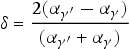
(1) Lattice mismatch between the γ/γ′ phase. The lattice mismatch between the γ/γ′ phase is defined as [2]:
(2) Solid solution strengthening of the γ′ phase. A large number of transition elements can be dissolved without destroying the long-range ordered structure of the γ′ phase. They can replace the occupation of Al or Ni atoms, playing the role of solid solution strengthening and improving the blocking effect on dislocation. Liu [9] adopted MD simulations to study the effect of Re on crack propagation at the interface of the γ/γ′ phase. By changing the occupancy of Re, it was concluded that crack propagation is brittle at low temperatures and ductile at high temperatures. Liu [10] adopted MD simulations to study the impacts of Re, W, Co and Ru on crack propagation and found that Re, Ru and W can inhibit crack brittle propagation, promote the deformation resistance of materials and strengthen materials. Co tends to aggravate the brittle propagation of cracks. In recent years, the effects of different element contents on the mechanical properties of nickel-based superalloys have been studied experimentally. Wang et al. [11] have studied the effect of the Ta content on the high-temperature tensile properties of Ni-based powder superalloys. It was found that the addition of Ta can improve the high-temperature tensile strength and yield strength of the alloy to a certain extent. At the same time, it can eliminate the boundary of original powder particles, promote the morphological instability of the secondary γ′ phase and increase the number of the tertiary γ′ phase. Ma et al. [12] investigated the microstructure and high-temperature durability of the alloy with a Mo content of 2–4% and concluded that the higher Mo content, the more μ phase precipitated. The precipitation of a large number of the rod-shaped μ phase seriously damaged the high-temperature durability of the alloy, while a small number of the μ phase did not regrade the high-temperature durability of the alloy. Luo et al. [13] found that Re significantly affects the durability of Ni-based single crystal superalloys. The appropriate amount of Re improves the endurance life of single crystal superalloys, while excessive Re weakens the stability of the alloy, promotes the formation of the Topologically close pack (TCP) phases and reduces the strengthening effect of Re on the alloy.
In recent years, the relationship between micro-morphology, dislocations and mechanical properties of Ni-based superalloys from the perspective of the γ′ precipitated phase has been investigated experimentally and theoretically. The finite deformation phase-field chemomechanics method was used to study solute segregation and dislocation–solute interaction. The results showed that both Cottrell and Suzuki type segregation of Co exists in γ and γ′. The solute element Co generally prefers the γ phase [14]. Wu et al. [15] revealed that Re tends to enrich in partial dislocations, hinders dislocation movement and improves creep performance using phase-field modelling. MD simulations mostly investigated the microstructure evolution of Ni-based superalloys under tensile and creep conditions, and have achieved remarkable results in simulating dislocation networks, expansion of micropore and crack growth [16-19]. However, there is little research on the correlation between the volume fraction, size and morphology of the γ′ phase and the mechanical properties of Ni-based superalloys. For Ni-based single crystal superalloy TMS-75, when the γ′ phase volume fraction is between 60% and 75%, the creep life reaches its peak [20]. Researchers believed that the morphology and size of the γ′ phase significantly affect the creep life of the Ni-based superalloys. It was found that the cubic γ′ phase shows the highest creep life, and its optimal size is about 500 nm [21]. In recent years, researchers have also established a Ni3Al embedded Ni model for simulation. It was found by Li et al. [22] that the initial structure of dislocation networks becomes irregular gradually, and the interfacial mismatch stress and the elastic modulus decrease slowly with the increasing. The increase in the strain rate contributed to the increase in the yield stress and tensile strength. Yin et al. [23] conducted MD simulations to study the mechanical properties of a two-phase model under uniaxial tension, and confirmed yield stress of different orientation models is: [111] > [001] > [011].
Researches have shown that the results of the embedded model are consistent with the experimental results [22-24]. Therefore, a model of the γ′ phase embedded the γ phase was established, and the deformation behaviour of a simplified model of nickel-based superalloys with different volume fractions of the γ′ phase was studied by MD simulations in this paper. The purpose of this work is to analyse the influence of the γ′ phase with different volume fractions on tensile properties of a simplified model of nickel-based superalloys by studying microstructure evolution and dislocation changes. In addition, the effects of different sizes and morphologies of the γ′ phase with equal volume fraction on the formation and expansion of micropore during stretching were discussed, and the relationship between microstructure evolution and mechanical properties was also explored. Meanwhile, the fracture modes caused by the γ′ phase with different sizes were manifested in the work. The research results of the paper are at qualitatively will agree with the real Ni-based superalloy and would provide potential research ideas for the design of new nickel-based superalloys.
Modelling and simulation
In this work, it was found that superalloy DZ411 is composed of the γ′ precipitation phase embedded in the γ matrix phase. The volume fraction, morphology and size of the γ′ phase were various in different samples during our experiment, as shown in Figure 1(a, b). The microstructure was obtained from electropolished and electrolysis of heat-treated superalloy DZ411 under ‘SUPRA55’ field emission scanning electron microscope. The electropolishing voltage was 10 V and the electrolytic voltage was 5 V. The samples were placed separately in the electropolishing solution and electrolyte for about 3 s. Since the γ′ phase plays an important role in strengthening superalloys, it is difficult to observe the whole process of the deformation mechanism in the γ′ phase with different volume, morphology and size directly by the experimental method. In the present study, MD simulations were performed for the idealised superalloy composed of Ni3Al precipitates (γ′ phase) and the pure Ni matrix (γ phase). It is obvious for actual superalloys that the γ matrix is not pure Ni, and the microstructure has certain amounts of other elements such as Cr, Co, etc. However, the multivariate interaction potentials of superalloys in MD simulation have not been developed, and this work focused on the role of the γ′ strengthening phase in the alloy, the models presented were simplified in order to study the failure behaviour through the dislocation motion of the γ′ phase at nanoscale.
(a) Spheroidal γ′ phase in DZ411 superalloy, (b) cubic γ′ phase in DZ411 superalloy, (c) small spherical γ′ phase, (d) small cubic γ′ phase, (e) big spherical γ′ phase and (f) big cubic γ′ phase cross-section (red atoms represent Al, blue toms represent Ni).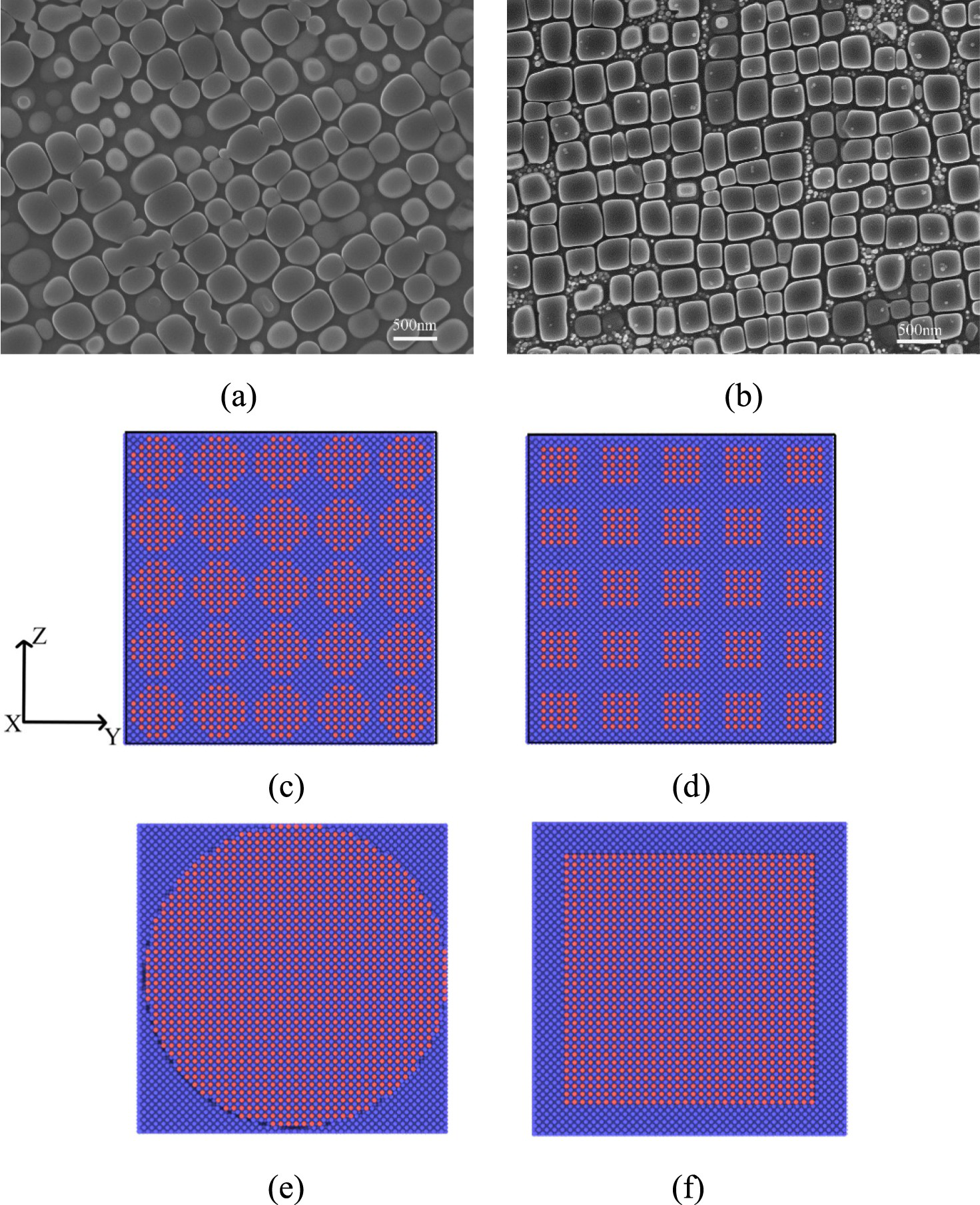
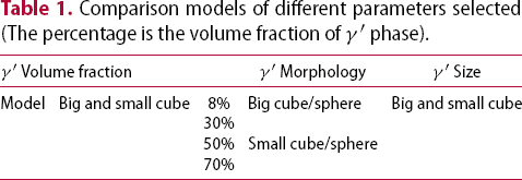
Comparison models of different parameters selected (The percentage is the volume fraction of γ′ phase).
Simulation results and analysis
Effect of the γ′ phase volume fraction on mechanical properties and microstructure evolution
The tensile stress–strain curves of small cubic and big cubic γ′ phase with different volume fractions are shown in Figure 2. The stress presents the same increasing trend in the elastic deformation stage and the curves overlap. The value of Young's modulus is obtained from the slope of the stress–strain elastic deformation stage. The volume fraction of the γ′ phase has no effect on Young's modulus. At the end of the elastic stage, the slope of each curve changes and all of them enter the plastic deformation stage. With the increase in the strain, the tensile stress reaches its peak at different strain levels. The peak stress is defined as the tensile strength, while the strain corresponding to a sudden decrease in stress is defined as the tensile elongation. As shown in Figure 2(a, b), the pure Ni model displays the highest tensile elongation, while the pure Ni3Al model shows the highest tensile strength, and the tensile strength of other embedded models are in between. For the big γ′ phase model, the tensile strength and tensile elongation decrease up to 50%. Tensile strength increases from 50% to 70% while the tensile elongation remains constant. The variation trend of the tensile strength and the elongation of small γ′ phase model are consistent with that of the big γ′ phase model, while the tensile strength and elongation of the γ′ phase model with 70% volume fraction have been significantly improved. The tensile strength reaches 19.8 GPa, which is the maximum value of all embedded models. It can be seen that the increase in the γ′ phase volume fraction will lead to the decrease in the tensile property of the model. However, in the case of high γ′ volume fraction to pure γ′ phase model, tensile strength and tensile elongation will increase again, which shows two opposite trends. The result is similar to the longest creep life in the experiment when the volume fraction of the γ′ phase is 65% [18].
Stress–strain curves of the γ′ phase with different volume fractions: (a) big cubic γ′ phase and (b) small cubic γ′ phase.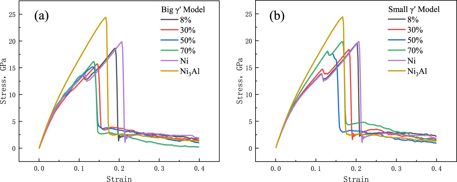
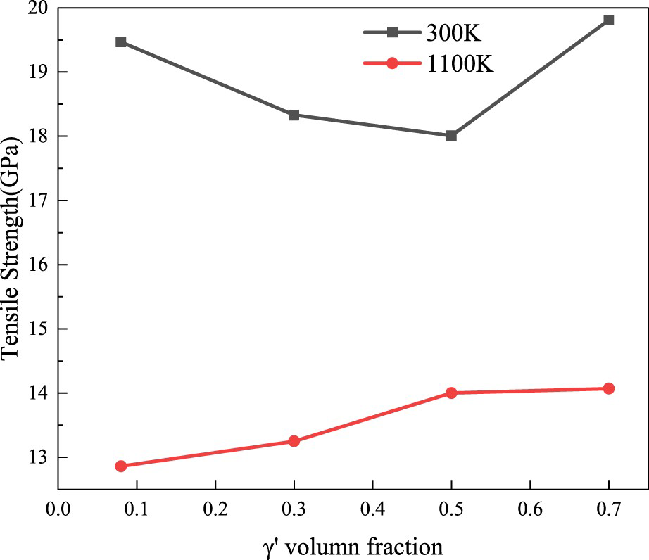
The deformation process of γ′ phase models with volume fractions of 30% and 70% are shown in Figure 3, which are used to analyse the evolution of microstructure under uniaxial tension. The model of the elastic deformation stage is filled with atoms of the FCC structure. In the plastic deformation stage, some atoms with the FCC structure are transformed into Hexagonal Close-Packed (HCP) structure and constitute stacking faults. According to the combination of stacking faults on different slip surfaces, it can be classified into three categories: The stacking fault surface with two adjacent layers is the intrinsic stacking fault, two separated layers represent the extrinsic stacking fault and the single stacking fault layer is the twin boundary [29]. Intrinsic stacking faults and extrinsic stacking faults appear in the initial plastic deformation stage of the model with the γ′ phase volume fraction of 30%. As the strain increases, it can be seen that the extrinsic stacking faults extend to the entire model. With the induction of partial dislocations, intrinsic stacking faults turn into extrinsic stacking faults. Fracture holes usually occur at the disordered atoms in the centre of the cross stacking fault, and a small number of atoms with FCC structure transform into Body-centered cubic (BCC) structure. Holes at the fracture of the model expand with increasing strain. Many stacking faults occur around the holes. The stacking faults away from the hole disappear and the atomic structure returns to FCC structure. At the initial stage of the plastic deformation, numerous BCC structural transformations occur in the γ′ phase model with a volume fraction of 70%, then intrinsic stacking faults are formed and start expanding, which leads to the emergence of a three-layer HCP structure atomic layer, showing three atomic structure transformations. As the strain increases, multiple holes appear. The reason is that when the strain is not high enough, the stacking faults on the surface cannot enter the regularly arranged γ′ phase. Stress concentration occurs in the γ phase matrix, resulting in multiple holes nucleation and expansion along the γ phase. The γ′ phase remains intact shape, keeping the flow stress relatively high in the early stage. In the later stage, pores in the matrix are connected and the γ′ phase are also severely deformed, and the stress drops significantly due to the higher strain. The tensile strength under different volume fractions of the γ′ phase at 300 K and 1100 K are shown in Figure 4. The tensile strength increases with the increase in the γ′ volume fraction at 1100 K, indicating that the enhancement effect of the γ′ phase is more obvious at high temperatures.
Snapshots of the model with 30% γ′ phase volume fraction during stretching: (a1) ε = 11.8%, (b1) ε = 18.8%, (c1) ε = 25.8% and (d1) ε = 32.8%. Snapshots of the model with 70% γ′ phase volume fraction during stretching: (a2) ε = 13.0%, (b2) ε = 16.8%, (c2) ε = 24.8% and (d2) ε = 34.8% (green atoms denote FCC structure, red atoms denote HCP structure, blue atoms denote BCC structure, and white atoms denote disordered atoms). Tensile strength (GPa) under different volume fractions of the γ′ phase at 300 K and 1100 K.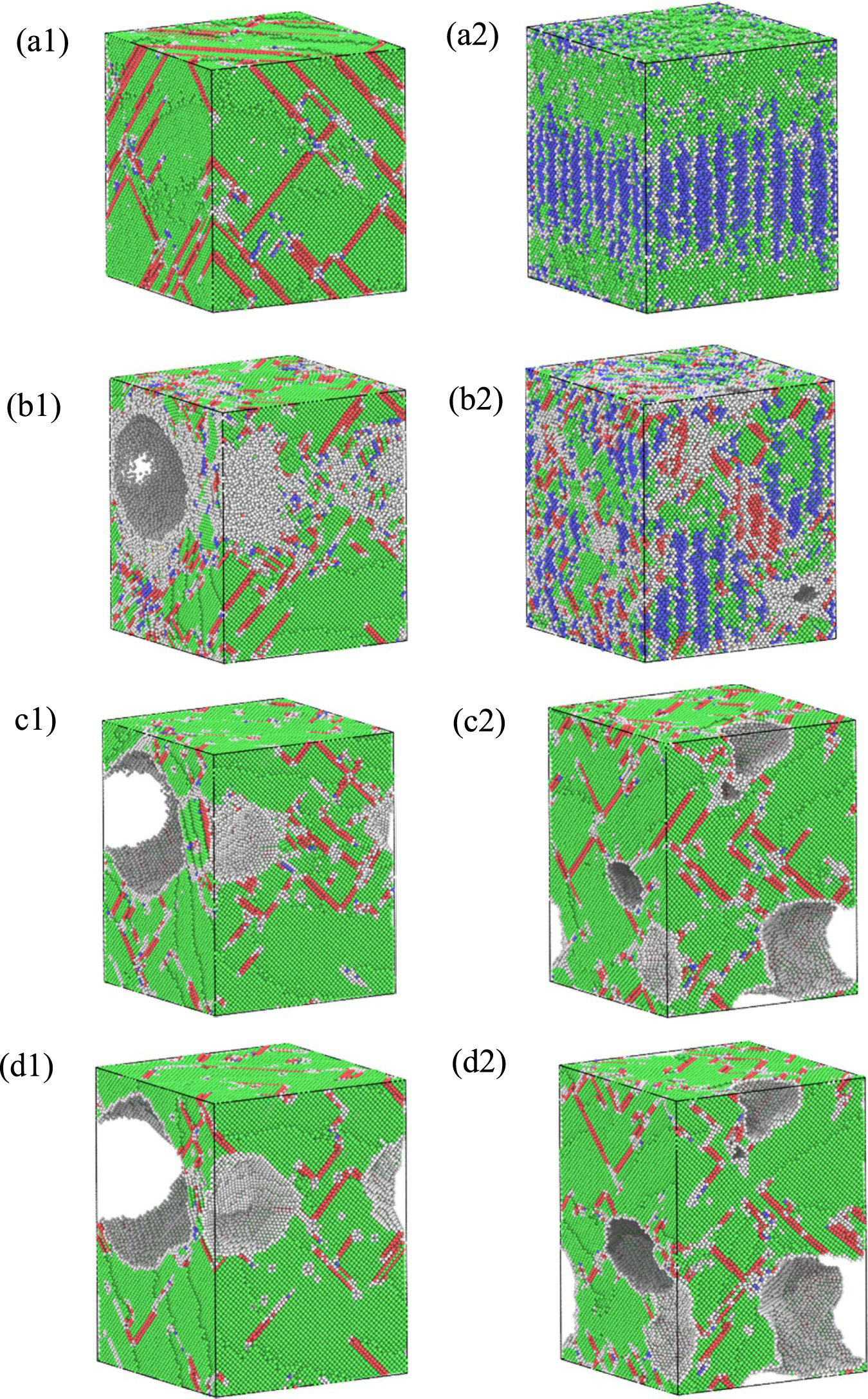
Effect of the γ′ phase morphology on mechanical properties and microstructure evolution
It was concluded that the γ′ phase presents cubic and spherical morphology from the experimental observation (see Figure 1). A comparative analysis of these two morphologies is constructed in this part. In the case of studying, the influence of morphology, the big γ′ phase model with 50% volume fraction and small γ′ phase model with 30% volume fraction are simulated to avoid the influence of other variables. Figure 5 shows the tensile stress–strain curves of different morphology models. It can be seen that the initial stage stress completely overlaps indicating that the γ′ phase morphology has no effect on Young's modulus. The tensile strength and elongation of the cubic γ′ phase model are both greater than that of the spherical γ′ phase model under the same volume fraction, so the cubic γ′ phase model has better tensile mechanical properties. Experimental results also showed that the cubic γ′ phase has the highest creep life [18]. The microstructure evolution and dislocation motion of the big and small γ′ phase models are analysed separately. Considering that the model is the γ phase wrapped γ′ phase, when observing the evolution of the microstructure, all Ni atoms are cut off, and the changes in the internal γ′ phase are observed through the changes in the position of Al atoms. Figure 6 illustrates the internal structure changes of the big cubic and spherical γ′ phase model with a volume fraction of 50%. Figure 7 illustrates the change of the atomic number of HCP structure during the stretching process. When there is no strain, a perfect dislocation is formed after relaxation due to the interface mismatch. The irregularity of the spherical γ′ phase interface results in the change of atomic configuration at the interface. However, according to the stress–strain curve, both of them have little effect on the subsequent stretching. In Figure 6(b1, b2), all stacking faults expand from the interface into the interior at the initial stage of plastic deformation. Figure 7(a) shows that the increasing number of HCP structure atoms is consistent with the stress growth. When the stress peak is reached, the number of HCP structure atoms also achieves the corresponding maximum value. It can be seen that stacking faults dominate the plastic deformation of the big γ′ phase model. In Figure 6(c1, c2), we can see that the stress drops rapidly after small holes appear, and the stacking faults begin to decrease slowly. From the snapshots of the microstructure, pores occur inside the cubic γ′ phase while voids in the spherical γ′ model appear inside the γ phase matrix. As shown in Figure 6(d1, d2), the cubic γ′ phase model retains more stacking faults after the generation of holes, which leads to the higher flow stress of the cubic γ′ phase model.
Stress–strain curves of the γ′ phase with different morphologies: (a) 50% big γ′ phase and (b) 30% small γ′ phase. Changes in the internal structure of the large cubic and spherical γ′ model with a volume fraction of 50%: (a1) ε = 0%, (b1) ε = 10.8%, (c1) ε = 13.8%, (d1) ε = 29.8%, (a2) ε = 0%, (b2) ε = 6.8%, (c2) ε = 19.8% and (d2) ε = 34.8%. Changes in atomic number of HCP structure during stretching. Top view of internal structure change of small cubic and spherical γ′ phase model with a volume fraction of 30%: (a1) ε = 0%, (b1) ε = 11.6%, (c1) ε = 15.8%, (d1) ε = 26.8%, (a2) ε = 0%, (b2) ε = 9.8%, (c2) ε = 13.8%, (d2) ε = 28.8%, (e) type of dislocation, (f) dislocation density of model, (g) stacking faults and (h) dislocations in γ phase channel.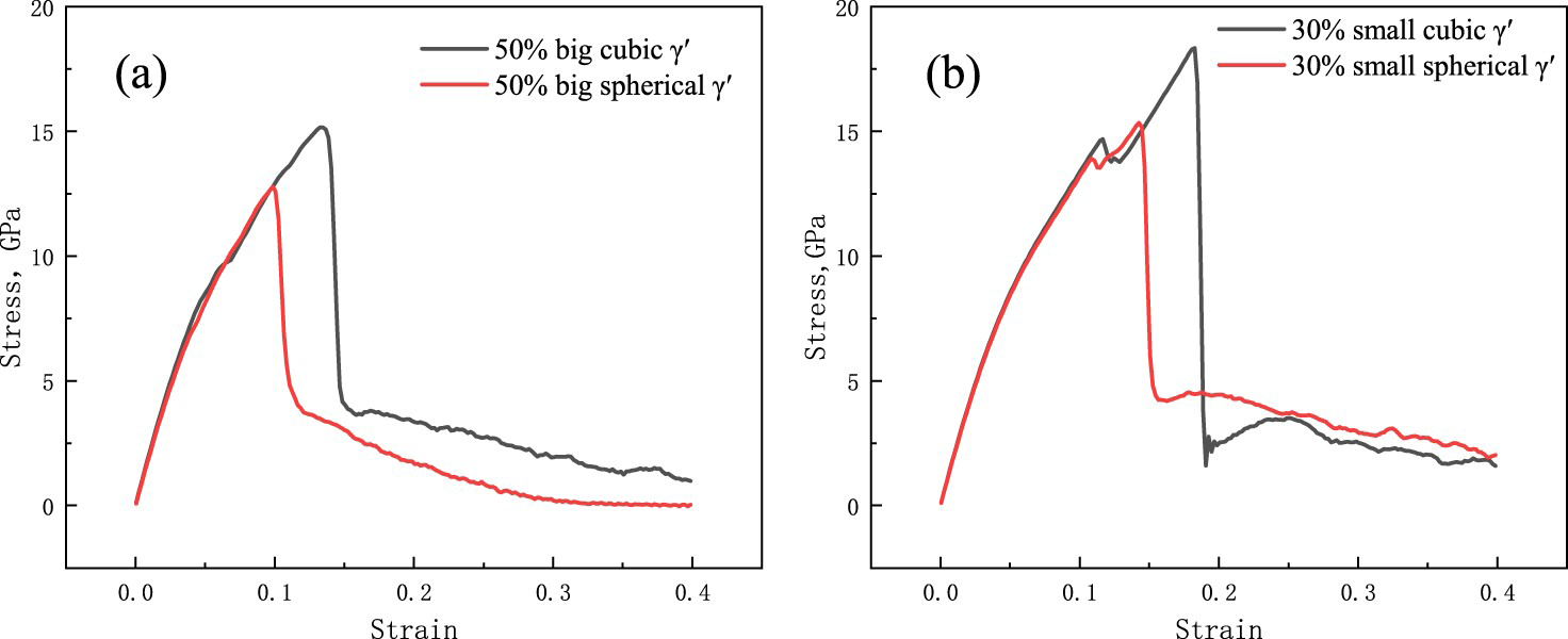
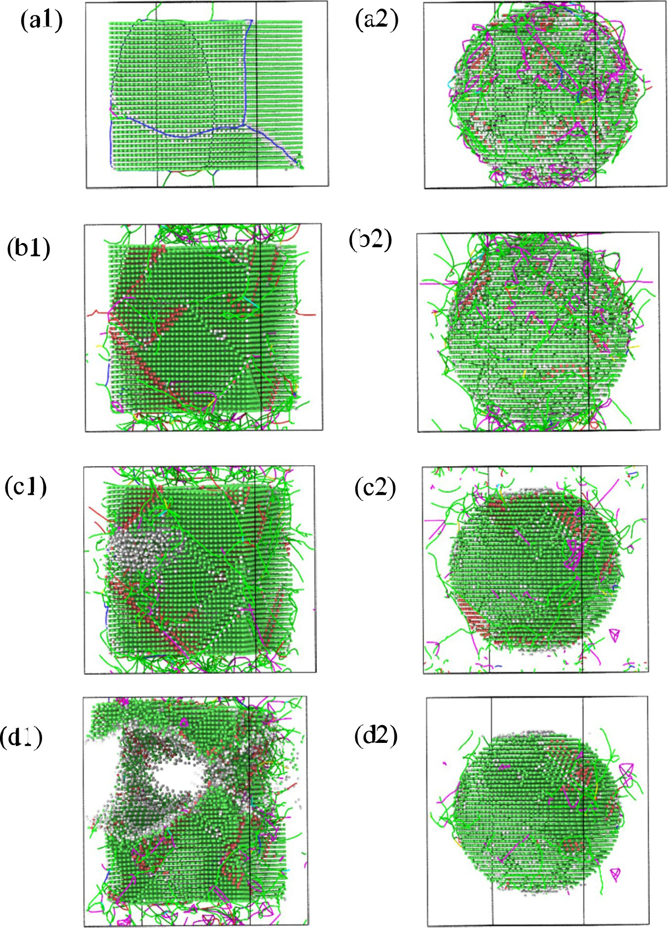
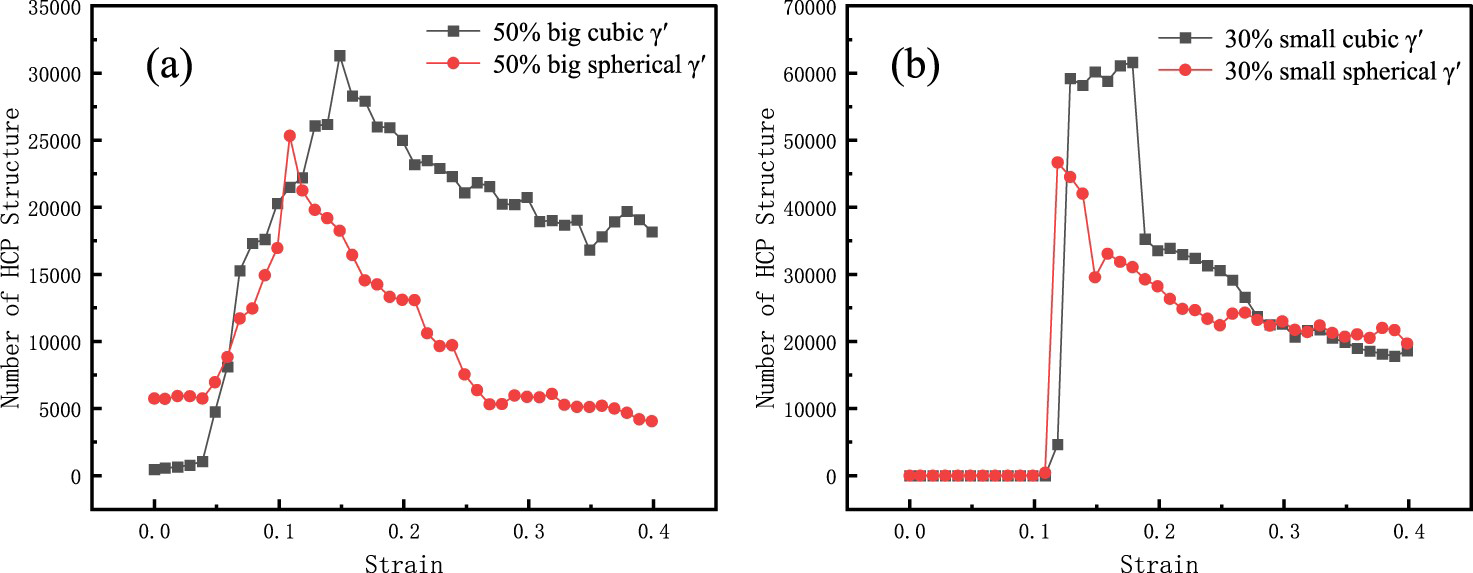
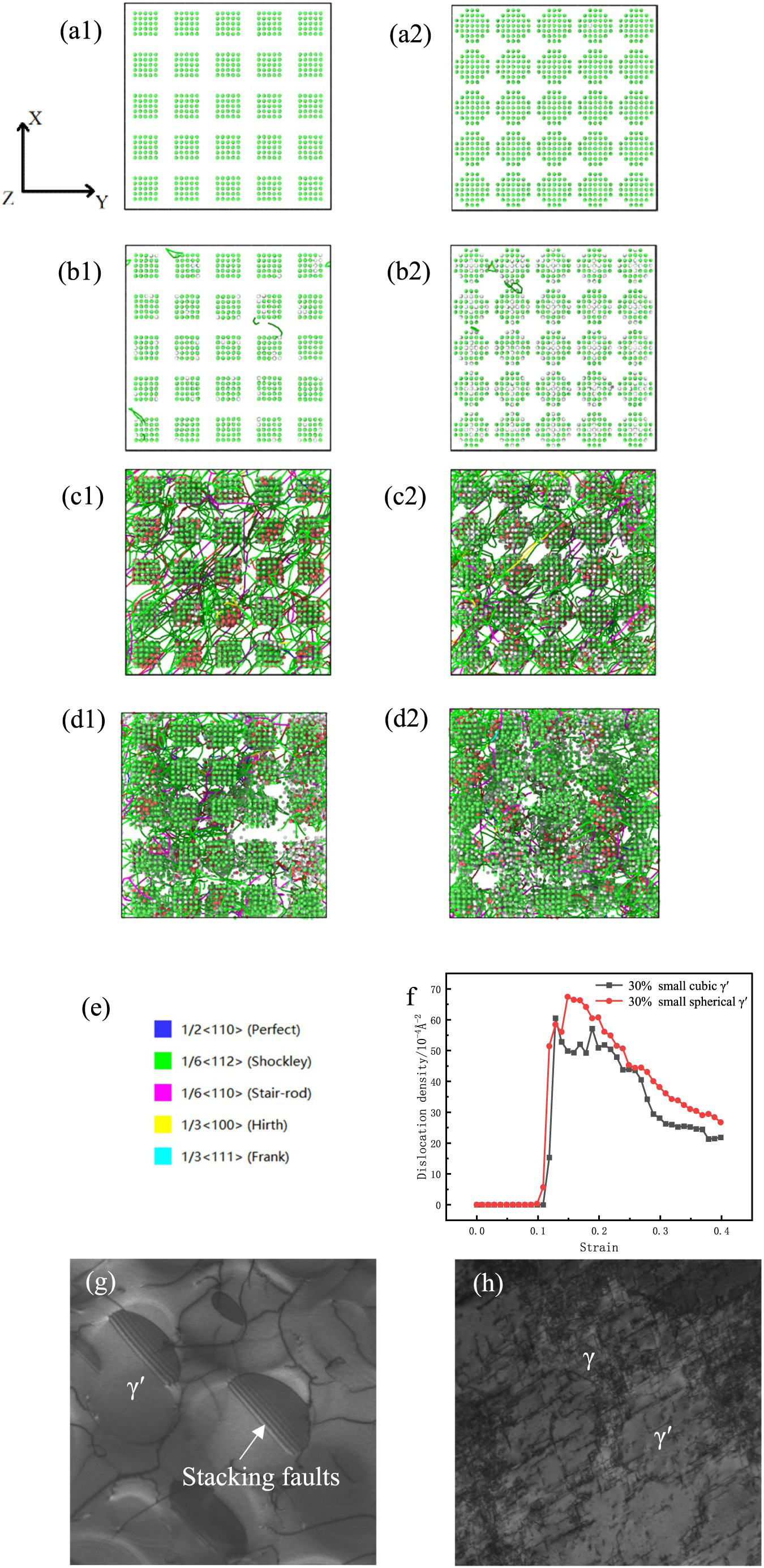
Figure 8 shows the internal structure change of the small cubic and spherical γ′ phase model with a volume fraction of 30%. The model presents a complete FCC structure as shown in Figure 8(al, a2). At the plastic deformation stage, partial dislocations appear in the γ phase channel, at the same time, some atoms in the γ′ phase are amorphised as shown in Figure 8(b1, b2), dislocations mainly exist in the form of a/6  Shockley partial dislocations. When the stress peak is reached, it is observed that the dislocations cut into the γ′ phase, leading to the expansion of the stacking faults into the γ′ phase and forming a stair-rod dislocation [30] (purple dislocations line) at two cross stacking faults as shown in Figure 8(c1, c2). This phenomenon was also found in the experiment shown in Figure 8(g). Dislocation accumulation occurs in the γ phase matrix channel, resulting in the small γ′ phase model fracture holes all occurring in the channel. A small amount of matrix dislocations in the γ phase cut into the γ′ phase and tangle with each other. This is similar to the dislocation morphology observed in the experiment shown in Figure 8(h). The cubic and spherical γ′ phase has undergone varying degrees of deformation with the increasing strain. The γ phase channel disappears and the γ′ phase coarsens away from the hole. At the same time, the number of stacking faults increased. However, the disordered atoms increase and the dislocations escape through the surface of the holes around the γ′ phase due to the further expansion of the holes. With the release of stress, part of the disordered atoms is restored to the FCC structure. From Figures 7(b) and 8(f), the variation trends of dislocations and stacking faults are completely consistent. Stacking faults on different slip planes react with each other to form a stair-rod dislocation due to the guidance of partial dislocations. A large number of partial dislocations disappear, and the stacking faults continue to expand forward after the meeting. The stair-rod dislocations at the tail disappear, resulting in a slight decrease in the density of dislocations while the stacking faults maintain a constant level. Owing to the strong resistance to dislocation cutting, the small spherical γ′ phase only forms stacking faults within the distance of 3–7 Å to its interface. The stress concentration in the γ phase channel is more serious, resulting in higher dislocation density and lower tensile elongation before fracture. During the flow stress stage, the expansion of holes causes the escape of dislocations and an increasing number of disordered atoms. As a result, the number of dislocations and stacking faults decreased.
Effect of the γ′ phase size on mechanical properties and microstructure evolution
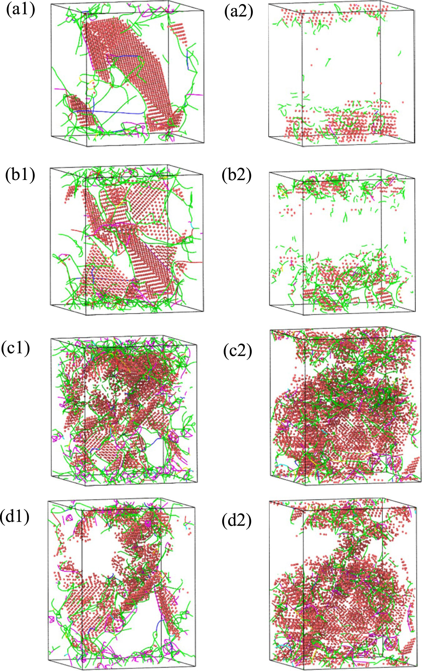
From the stress–strain curves of different γ′ phase sizes with the same volume fraction in Figure 9, it can be seen that the γ′ phase size has little effect on Young's modulus, and the regular distribution of the small γ′ phase in γ phase can improve the tensile strength and elongation, showing the better mechanical properties. We select a volume fraction of 50% to analyse the microstructure evolution and dislocation motion of the γ′ phase model shown in Figure 10. The big γ′ phase model clearly shows the distribution of stacking faults and dislocations during plastic deformation. Many dislocations occur in the γ phase and part of them cuts into the γ′ phase. This results in the stacking faults on the (111) surface at the eight vertices of the cube, and the distribution of the stacking faults on the diagonal of the cubic γ′ phase (see Figure 10(a1, b1)). The partial dislocations induce stacking faults to spread throughout the γ′ phase with the strain increases. The fracture occurs when the strain reaches 17.8% (see Figure 10(c1)), at the same time, the regularly distributed stacking faults only remain around the pores. With the generation of micropore and short dislocations at a distance, the atomic distribution of the HCP structure becomes chaotic. New fracture holes are formed in the model with the increasing of strain (see Figure 10(d1)). Numerous dislocation loops are broken and the expansion of the holes in the γ′ phase causes softening, which makes the flow stress continue to drop (see Figure 9(c)). The plastic deformation stage of the small γ′ phase model presents a new change. Dislocations in the γ phase channel induce part of the γ′ phase to deform firstly, and the stacking faults are generated inside the γ′ phase on both sides of the channel (see Figure 10(a2)). Then, the dislocations slip in the γ phase matrix channel along the tensile direction. During the movement, the dislocations continue to cut into the undeformed γ′ phase to form the stacking faults inside. Finally, the accumulation of dislocations and stacking faults exist in all small γ′ phases of the model (see Figure 10(b2)). The fracture also occurs at this stage. The hole sprouts in the γ phase cross channel and expands in four directions as the strain increases. The surrounding small γ′ phase deforms seriously, while the small γ’ phase far away from the hole still maintains a complete cubic shape (see Figure 10(c2)). The dislocation cuts into the small γ′ phase and remains (see Figure 10(d2)), resulting in softening, which makes the flow stress of the model decrease (see Figure 9(c)).
Comparison of tensile stress–strain curves of different sizes of the γ′ phase under the same volume fraction: (a) 8% γ′ phase, (b) 30% γ′ phase, (c) 50% γ′ phase and (d) 70% γ′ phase. Microstructure evolution and dislocation motion analysis of the γ′ phase model with a volume fraction of 50%: (a) big γ′ phase model, (b) small γ′ phase model, (a1) ε = 8.2%, (b1) ε = 11.8%, (c1) ε = 17.8%, (d1) ε = 34.8%, (a2) ε = 13.8%, (b2) ε = 14.0%, (c2) ε = 20.6% and (d2) ε = 34.8% (the red atoms represent Al atoms with HCP structure).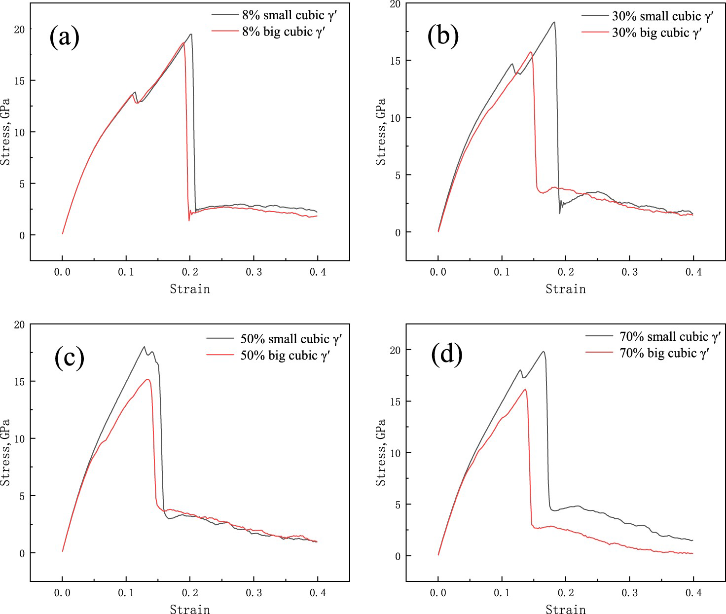
Conclusion
Without considering the influence of other precipitates and elements, through MD simulations, using the idealised model of nickel-based superalloys with the γ′ phase embedded in the γ phase, the effects of the volume fraction, morphology and size of the γ′ phase on the microstructure evolution and mechanical properties were investigated. The main conclusions are as follows:
Compare the effects of different volume fractions of the γ′ phase on the tensile properties of the γ/γ′ two-phase model. The results show that for the embedded model, when the volume fraction is less than 50%, the more the volume fraction of the γ′ phase, the lower the tensile strength and tensile elongation. While the volume fraction of the γ′ phase is more than 50%, which reaches 70%, the tensile strength and the tensile elongation have increased again. A volume fraction of 50% considered as a critical value that affects the variation trend of mechanical properties. The cubic γ′ phase presents better mechanical properties than the spherical γ′ phase. The stacking faults formed in the cubic γ′ phase model are more stable, so the integrity of the cubic γ′ is better than that of the spherical γ′ under higher strain. Severe plastic deformation takes place in the big cubic γ′ phase under axial tensile stress. Holes develop and eventually lead to failure. However, in the small cubic γ′ phase model, the plastic deformation occurs following the movement of dislocations gradually. Holes appear at the intersection of the γ phase channel and extend along the channel. In the case of the same volume fraction and the same size of the γ′ phase embedded model, the mechanical properties of the γ′ phase are better when they are small in size and regularly arranged.
Footnotes
Acknowledgments
The authors would like to thankfully appreciate Prof. Chen Xi and Dr. Xiao Hang for illuminative guiding and constructive suggestions.
Data availability statement
The processed data required to reproduce these findings can be shared.
Disclosure statement
No potential conflict of interest was reported by the author(s).