
Abstract
Combined shear-compression tests were conducted to AZ31B magnesium alloy through shear-compression specimen (SCS) and the deformation response process is captured by digital image correlation technology. The mechanical behaviours and deformation characteristics of SCS with different loading angles are analysed in detailed. Results show that the strain path of SCS is sensitive to the loading angle. The deformation behaviour at initial stage exhibits proportional loading and related to the tangent loading angle which reveals the designability of SCS for mechanical testing with specific requirements.
Keywords
Magnesium alloys are widely used in various areas such as auto industry, aviation field for their excellent performances i.e. high specific stiffness, low density and so on [1-5]. The growing interest in energy conservation and emission reduction improves the utilisation of these lightweight alloys and then continues raising the requirements in understanding their mechanical properties [6-9]. Many reports studied the compression [8], tension [7,10,11], pre-deformation [1,12,13] and impact mechanical responses [8,14] of such materials. These contributions help a lot on constructing the constitutive model of Mg alloy which helpful to provide accurate predictions on stress–strain and force-displacement responses [7,15,16]. Therefore, a reliable parameter calibration is required for accurately modelling. Spontaneously, the mechanical properties of materials under complex loading conditions should be clarified for the establishment of a full stress constitutive relation whose internal variables involve six independent stresses component and six independent strains component. The previous efforts have made some progress in such areas [4,17-22]. Yang et al. [17] studied the combined shear-compression mechanical behaviours of AZ31 Mg alloy through SCS and analysed its failure mechanisms under different states of stress. Steglich and Besson also investigated the failure behaviours of Mg alloy sheet under mixed-mode loading by using Arcan device [21]. In our previous investigation [23], the combined mechanical responses of AZ31B Mg alloy were studied through a specific loading device consisting of two metal blocks with single bevelled ends and a sleeve made of Teflon. The strain concentration of Mg alloy specimen was observed and found decrease with increasing loading angle. Instead of using additional loading device, Jin et al. [15,24] conducted the multi-axial test on Mg alloy through combined shear-compression specimen (SCS) developed by Rittel [25]. Compared to the method utilised in Lv et al. [23], the SCS set up provides a simpler method to obtain the combined mechanical responses of materials. This is the primary reason SCS method is selected to conduct the combined loading test in present contribution. However, most investigations related to SCS focus on the force and stress responses of specimen and few literatures reports the deformation and strain responses of SCSs [17,26,27]. This is one of the main drivers of this work.
In addition, it should be pointed out that the parameter calibration of a constitutive model depends heavily on the accurate feedback of the states of stress or strain [28]. This means the stress/strain of tested specimens should be effectively detected or identified. However, the determination of experimental stress and strain states is still mostly depending on hypothesis. Certainly, the state of stress can not be obtained experimentally, however, the development of digital image correlation (DIC) technology increases the efficiency of strain measurement [29]. Combining the requirements of complex load tests and precision measurement of strain, the DIC technology is used to measure the deformation and strain field of SCS under combined shear-compression. The major aim of this work is to identify the deformation and strain responses of SCS with different loading angles exactly and then provide the research strategies for experimental development especially in the modelling of constitutive and failure behaviours of materials.
In this communication, the AZ31B magnesium alloy provided by Dongguan Tianguan Metal Material Co., Ltd was utilised in the combined shear-compression tests. In order to introduce the additional shear component into the compression, the SCS prepared through wire cut electrical discharge and machining was applied instead of the complex load device. Figure 1(a) displays the schematic diagram of SCS and loading angle is denoted as
Schematic diagram (a) and front view (b) of SCS as well as the speckle (c) and the deformation processes and force-displacement curves of SCS with different loading angles of 15o, 30o and 45o. . This is used to control the magnitude of introduced shear component. In addition, SCS with three different loading angles of 15, 30 and 45 o are selected for the combined shear-compression tests. It should be emphasised that the gauge section of SCS is the designed area where deformation occurs. Then the additional shear component can be introduced by geometric effect results from the inclined gauge section. The mechanical tests were conducted through a universal material testing machine (CTM8000, Wance, Shanghai, China) with a load cell of 100 kN. The SCS was placed between two metal plates with the boundary conditions of one side fixed and the other side satisfied the displacement boundary with the loading rate of 2 mm/min.
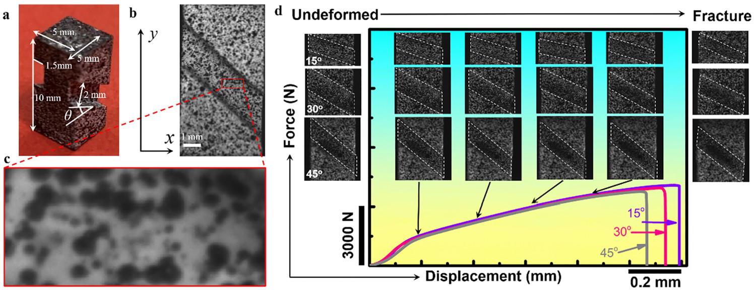
In order to investigate the deformation responses of SCS with different loading angle, the digital image correlation (DIC) technology (MatchID 2D, MatchID NV, Belgium) was employed to detect the deformation process of tested specimens. An industrial charge couple device (CCD) camera purchased from FLIR Systems, Inc. was used to capture the deformation pictures of SCS during loading with the frame rate of 15 fps. The random speckle was prepared onto the specimen surface for DIC analysis as shown in Figure 1(b) and (c). Additionally, the subset and step size during DIC analysing were set to be 21 pixels2 and 10 pixels, respectively.
Figure 1(d) shows the deformation images and the force-displacement curves recorded by testing machine of SCS with different loading angles. It can be found that the deformation features of the surface of the gauge section can not be identified clearly for the existence of sprayed speckle onto the specimen. The SCS exhibits the similar force responses during the entire loading until the fracture. It can be found that the fracture displacement of SCS decreases with increasing loading angle. This indicates that the stress/strain state of SCS can be controlled by adjusting the loading angle and the mechanical behaviours of AZ31B Mg alloy are sensitive to the stress/strain state.
In order to observe the deformation process of SCS clearly, Figure 2 displays the strain cloud pictures. The distributions of strain supply the basis for the analysis of the changing in strain during the whole loading process. The reference coordinate system of the strain components (
Strain field histories of SCS with different loading angle of 15o (a), 30o (b) and 45o (c) during loading. ,
,
 and
and
 ) in strain cloud pictures is
 as displayed in Figure 1(b). On the whole, the strain field underwent the transformation from uniform deformation in the elastic stage to localisation of deformation in plastic stage. Then the SCS with different loading angles failed with macroscopic fracture. The fracture failure can be attributed to the highly localised strain. The strain localisation starts at one side of the intermediate cross-section of the gauge section and then extends to the whole intermediate cross-section. This means that a band where strain localisation occurs and divides the total gauge section into three parts. One is the strain localisation area provides the most plastic deformation and the rest two parts can be regarded as the areas in which uniform plastic deformation occurs. The uniformly deformed region is symmetrical distributed about strain localisation band. In each part of above three areas, the strain level can be regarded as homogeneous. Therefore, the histories of strain components at the central point of the gauge section were selected for the quantitative analysis of the deformation responses of SCS under combined shear-compression loading.
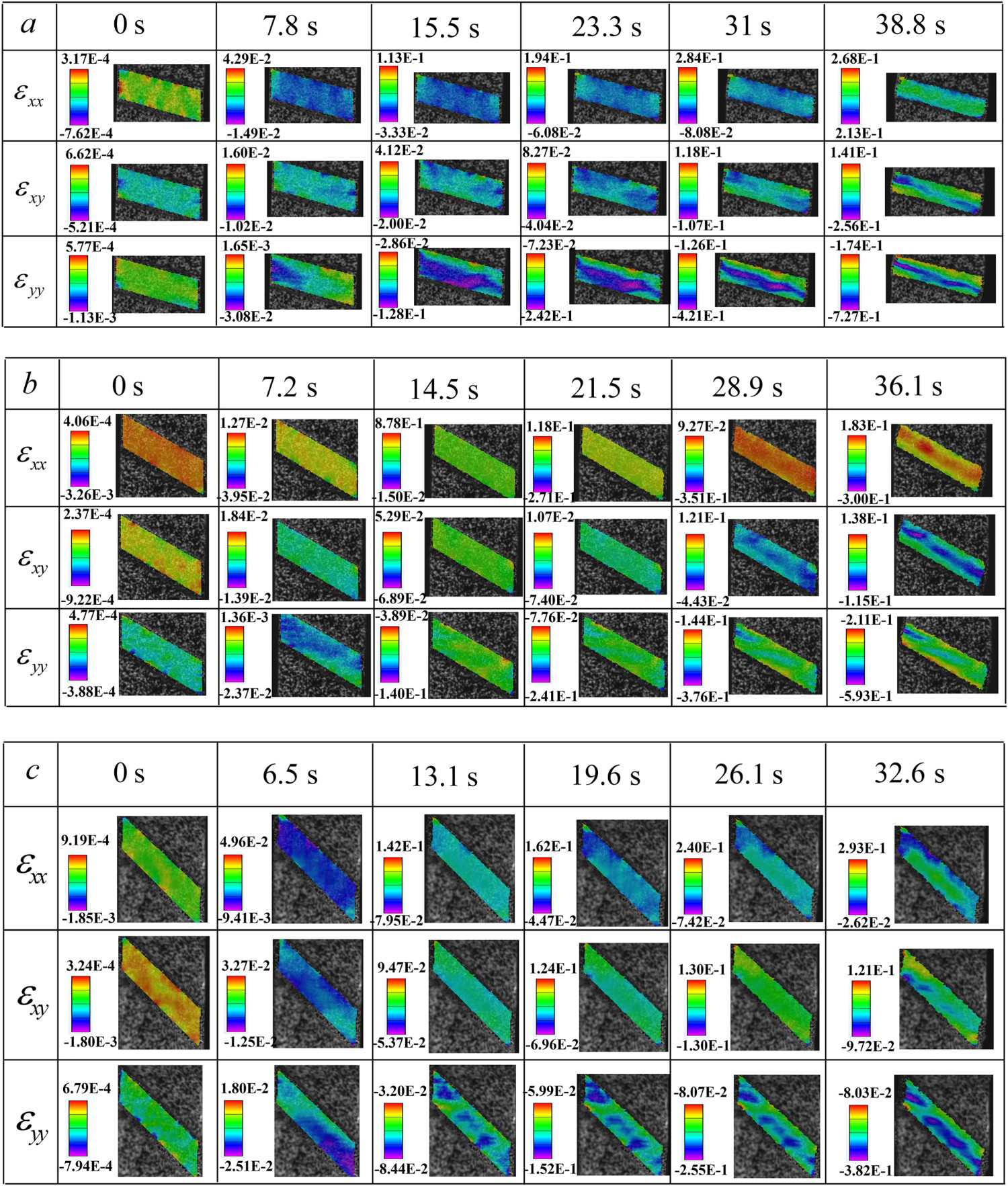
Figure 3 shows the quantitative analysis of the strain component histories at the central point of SCS during the entire loading process in different reference coordinates i.e.
Strain analysis of SCS,
Comparison of
and the corresponding the tangent value of loading angle. and
and
 . The coordinate
 relates to the globe reference frame of DIC system. Figure 3(a) illustrates the corresponding strain components
 ,
,
 and
and
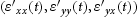
 in globe reference frame. However, more intuitive assessment of strain state should be carried out in another reference frame i.e. the local coordinate system
 . The coordinate axis in
 directly reflects the parallel direction to normal strains
 and
and
 as well as the in-plane shear strain
 . Figure 3(b) and (c) displays the transformation rule between
 and
and
 and strain values of
 ,
,
 and
and
 in
in
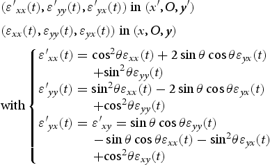
 , respectively. The specific transformation formula can be expressed as follows [23]:
 ,
,
 contributes the most of the plastic deformation and exhibits decreases with increasing loading angle while the opposite is true for
 . The shear strain
 shows the unexpected decreases with loading angle. This phenomenon can be attributed to the inappropriate selection of reference coordinate system. In fact, the local material direction changes with loading angle, while the globe coordinate
 is fixed, which results in the non-intuitive measurement of the shear strain. Therefore, it is necessary to monitor the strain state of SCS in local coordinate system
 . Through Equation (1), the transformed strain components
 can be obtained as shown in Figure 3(c). It can be observed that the deformation mechanism of SCS changes from compression dominant to shear dominant with increasing loading angle as expected. In particular, the SCS with loading angle of 15o,
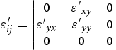
 almost equals to 0 during the entire loading stage. This means the state of strain within the gauge section of SCS (loading angle = 15o) can be approximated as uniaxial state with the strain expression of:
 begins to contribute to the total deformation of SCS. Then the strain state becomes:
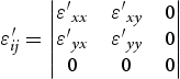
 and
and
 increase and
 decreases with increase of loading angle. Figure 3(d) shows the nonlinear strain path i.e.
 vs.
vs.
 . Furthermore, the curvature of strain path increases with loading angle. However, when the value of
 within the range of [−0.05, 0], the deformation process can be regarded as linear as shown in the partial enlarged drawing. The strain path can be described by the slope of the linear line i.e.
 . It can be found that the strain path is quantitative controlled by the tangent value of loading angle as listed in Table 1.
 is displayed in (a), (b) shows the rotation axes for the coordinate transformation, (c) shows the transformed strain components
 , and the strain paths in shear-normal strain space are displayed in (d).
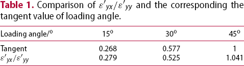
In summary, the deformation responses of SCS are sensitive to the loading angle and change from compression dominant to shear dominant as loading angle increases. The whole deformation process of SCS is non-linear and the degree of nonlinearity has positive correlation with loading angle. However, at the initial stage of deformation, the ratio of
 to
to
 is almost kept constant and the strain path can be regarded as proportional loading. In addition, the loading ratio of strain components can be controlled by setting various loading angles and the relation between loading ratio and loading angle can be quantitatively described by tangent value of loading angle.
Based on the results and analysis above, the experimental method can be utilised in calibrating the model parameters in failure criterion and constitutive relation of materials under multi-axial loading. Furthermore, the future investigations should be concerned on obtaining the stress components of SCS and the establishment of test criteria.
Footnotes
Disclosure statement
No potential conflict of interest was reported by the author(s).