
Abstract
Simple shear extrusion was designed in 2009 as a novel severe plastic deformation technique to obtain ultrafine-grained materials. During the past years, extensive work has been done to introduce and clarify this technique's characteristics and investigate its application in different areas of materials science and engineering. Owing to the inherent phenomenon of strain reversal associated with this technique and different available processing routes, this method is proven to be useful in material processing. This article aims to summarise the ability of this process to produce ultrafine-grained materials and discuss the potential of this process for industrialisation.
Keywords
Introduction
Severe plastic deformation (SPD) methods are used to convert coarse grain metallic materials and alloys into UFG materials, including equal channel angular pressing (ECAP) [1-3], high-pressure torsion (HPT) [4], accumulative roll bonding (ARB) [5,6], and many other techniques [7-10]. These techniques can produce materials with superior mechanical and physical properties. Working under high hydrostatic pressures is the essential feature of these processes from the perspective of workability [11]. Indeed, creating such conditions would result in high stresses in the die set; therefore, it requires very forceful tools such as diamond anvils in HPT [12]. Since the stress state in the workpiece and the die set is strongly dependent on the design of the die and its geometry, researchers have always tried to design techniques to make the high value of hydrostatic pressure while the resulting tensile stresses on apparatus to be minimum. Simple shear extrusion (SSE) is an SPD technique developed during the last ten years and has all the characteristics mentioned above.
The idea of SSE arises from the fact that the best deformation mode for generating UFG materials is the simple shear mode. Higher levels of effective strain in this mode [13] may lead to excessive generation of dislocations, followed by the formation of cell structures inscribed by a network of low-angle grain boundaries. Subsequent rotation arising from this mode [14,15] further transforms these low-angle grain boundaries into high-angle ones. In its very nature, it is the desired grain refinement. There are some similarities between this technique and twist extrusion (TE) [16]. Both are based on direct extrusion [7] and can easily be installed on any standard extrusion equipment set in industrial production lines [17]. Furthermore, the amount of waste material at the front and rear of samples is significantly reduced compared to ECAP processed samples [18]. However, SSE and TE are basically different in the way the specimen deforms through the extrusion channel.
SSE was born during the MS thesis of Nima Pardis under the supervision of the first author. This technique was then developed through several MS and PhD theses in the last ten years. The research team involved in developing this technique includes Nazanin Bayat Tork (MS and PhD theses), Ebad Bagherpour (MS and PhD theses), Zahra Abbasi (MS and PhD theses), Hasan Sheikh (PhD thesis), Alireza Rezvani Haghighi Shirazi (MS thesis), and Faraz Rahimzadeh Lotfabad (MS thesis).
Commercially pure aluminium and copper as model materials were frequently used to investigate and clarify the characteristics of SSE. Regarding gradual deformation in SSE, hard-to-work materials such as magnesium [19], magnesium alloys [20-22], and TWIP steel [23] were processed by this technique. Besides the experimental works, finite element (FE) simulations were employed to investigate the materials’ mechanical behaviour during deformation and obtain strain distribution on the sample cross-section [18]. The effects of processing parameters such as materials strength and friction factor on the required load were also investigated by FE simulations [24]. The length of the deformation channel was optimised using the upper bound technique [25]. In another research work, suitable annealing time–temperature ranges were presented to optimise the mechanical properties of severely deformed copper [26]. Microstructural evolutions and texture development through the first deformation pass and subsequent passes were well investigated using TEM, EBSD [27,28], and crystal plasticity finite-element method (CPFEM) [29,30]. The latest achievement in the design and manipulation of the geometry of this process toward the more potential of being industrialised was done by the introduction of circular CSSE [31-33]. Recent works showed that the use of nanostructured materials in microforming processes could eliminate the size effect in these processes. This illustrates one of the important applications of nanostructured materials in advanced industries such as microforming.
SSE has been partially reviewed and discussed in the literature, mostly in terms of comparison between different SPD techniques [34-40]. However, this technique and its variant, CSSE, pose several distinctive features that are thus far published in separate articles. This article aims to unite the literature behind the SSE and present how this technique originated and evolved. The methodology adopted here is to discuss the ability of this process to produce bulk nanostructured materials in connection with the fundamental works on SPD techniques. Lastly, in this article, the potential of this process to become industrialised will be discussed since the practical applications are the final goal of any development in materials science and engineering.
Principals of SSE
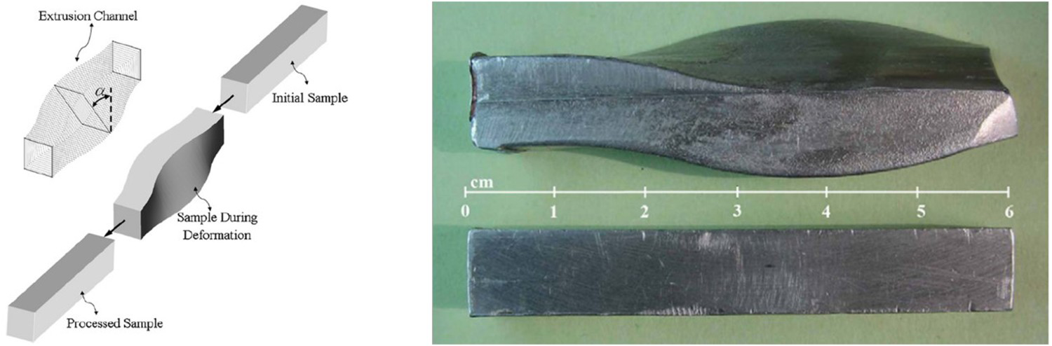
This method is based on pressing a billet of material through a specially designed channel of a direct extrusion die. According to Figure 1, as the sample passes through the channel, it deforms gradually while its cross-section area remains constant. The square cross-section of the billet gradually changes to a parallelogram with the same area in the middle of the channel and then retains its initial shape through the second half of the channel. The strain imposed in this process depends on the maximum distortion angle in the middle, which can be ideally calculated as follow [18]:
Schematic illustration of SSE (left) and real sample during deformation (right) [18].
Distortion angle profile and optimisation of linear die profile
One of the distinctive features of SSE is that the variation of the distortion angle (
SSE die with a linear profile [25]. ) with the position along the channel length (x) could be manipulated. The importance of such a feature will be discussed further in section ‘Processed Materials’. In the original design of the SSE die, the variation of distortion angle (
 ) with the position along the channel length was non-linear. Such a profile results in enormous complications during the optimisation of the die design. Therefore, in the next step, an SSE die with the linear angular profile (Figure 2) is considered and subjected to optimisation by the upper bound theorem [25]. Such optimisation is crucial for any industrial-scale or laboratory-scale forming process since, in the optimum situation, lower loads are required to complete the process.
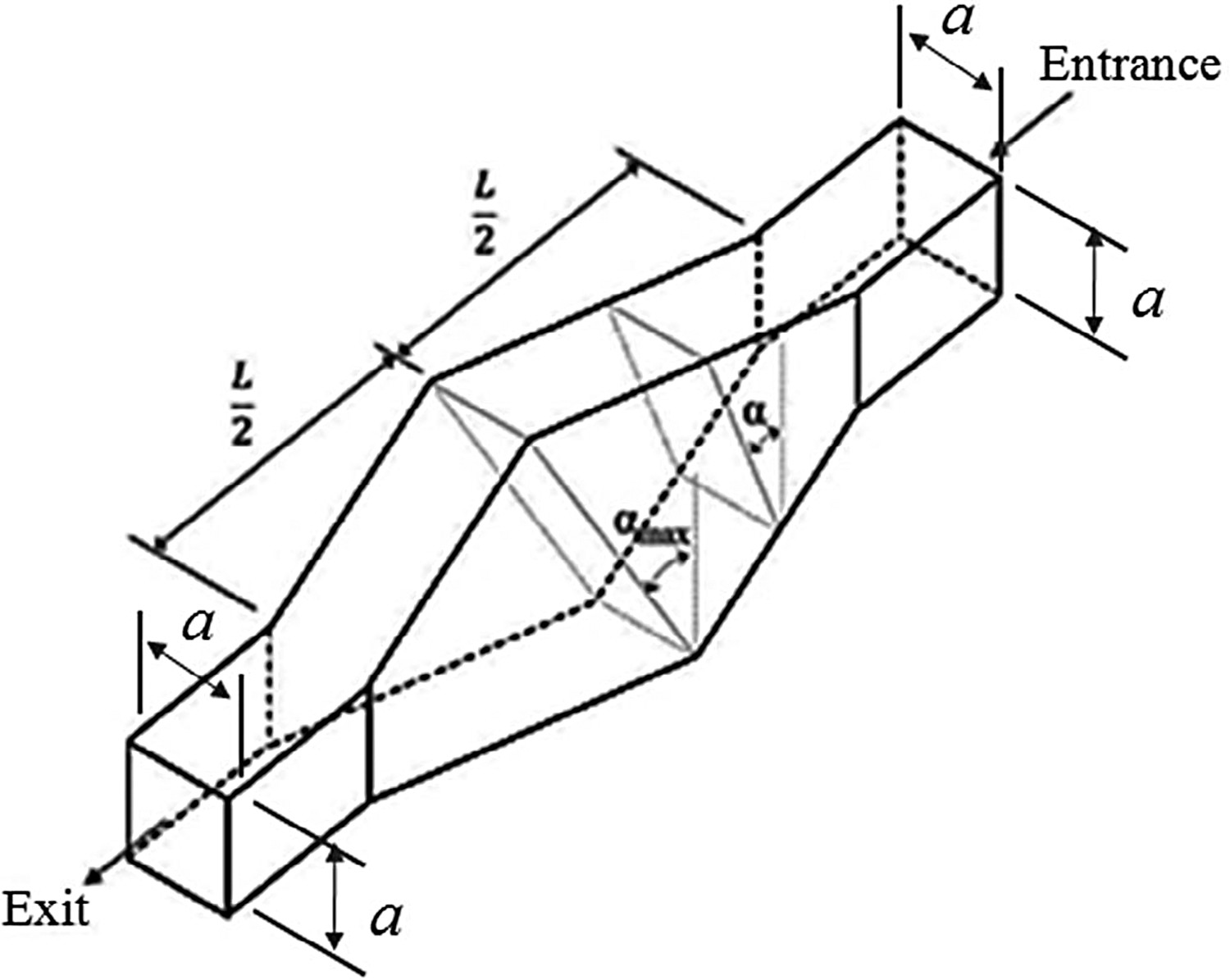
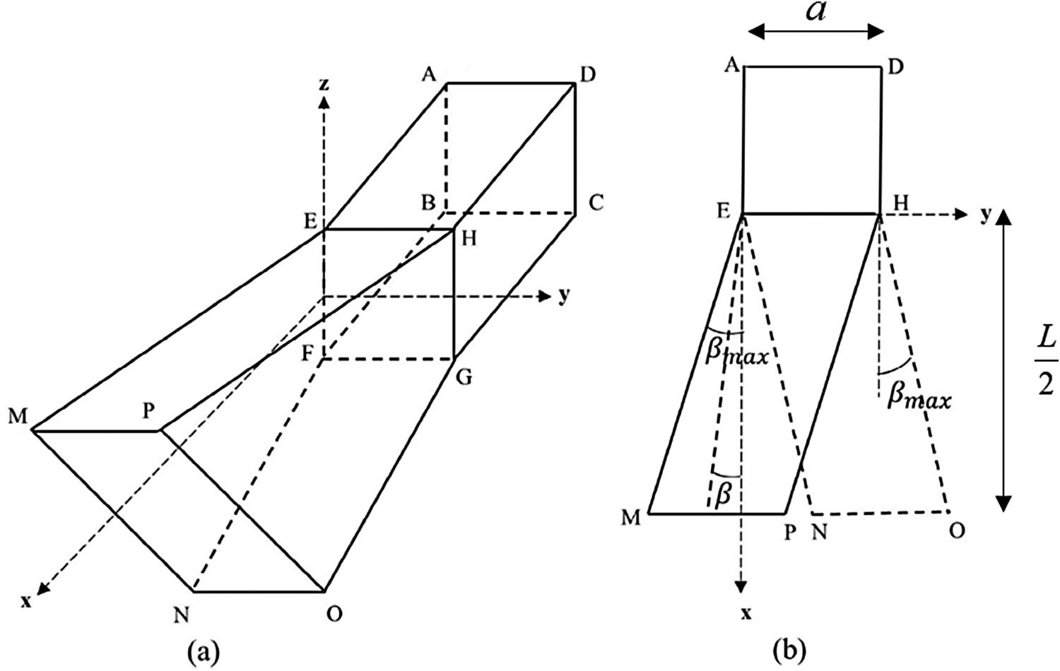
The linear die profile could be described in terms of four geometrical parameters: maximum distortion angle (
(a) Isometric and (b) top view of SSE die with linear distortion angle profile (only half of the channel is drawn) [25]. Variation of the optimum relative length of the channel (
 ), maximum inclination angle (
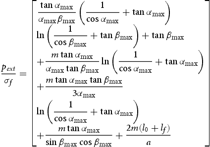
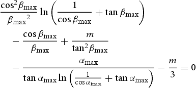
 ), channel length (L), and inlet wall length (a) (Figure 3). The relation between these parameters reads as follows [25]:

 ) as a function of
 for different values of m.
The final shape of the specimen and waste of material
One of the main practical problems during some SPD processes such as ECAP is that the final shape of the specimen is in a manner that needs to be machined before performing the second pass (e.g. sample's tail in ECAP). The occurrence of such inhomogeneities decreases the efficiency of the process since, after several passes, a considerable amount of material will be removed [41-43]. Figure 5 compares the sample's final shape after deformation by SSE and ECAP obtained from FE simulation (assuming no backpressure is exerted). As it can be seen, the amount of waste material is considerably lower for the sample processed by SSE compared to the one processed by ECAP [18]. A similar case is also reported for materials processed by TE with an application of no backpressure [44].
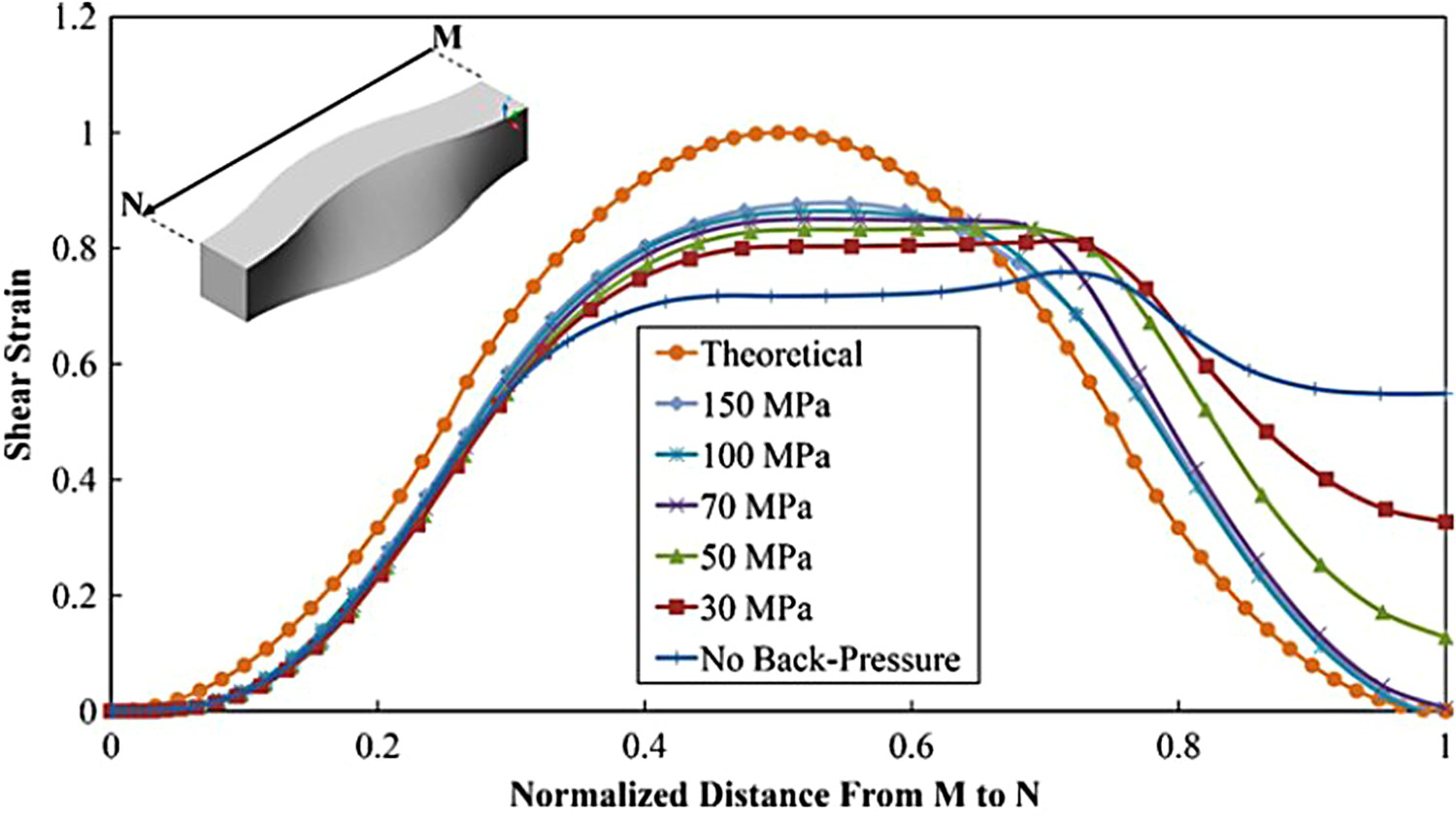
(a) Real sample processed by SSE for one pass, (b) simulation result of the shape of the sample after one pass of SSE, and (c) the simulation result of the sample processed by ECAP for one pass [18]. Cross-section of the specimen at middle and end, processed by SSE with different values of backpressure [18]. Distribution of shear strain through the length of the channel for different imposed backpressures predicted by FE simulation compared to theoretical distribution [18].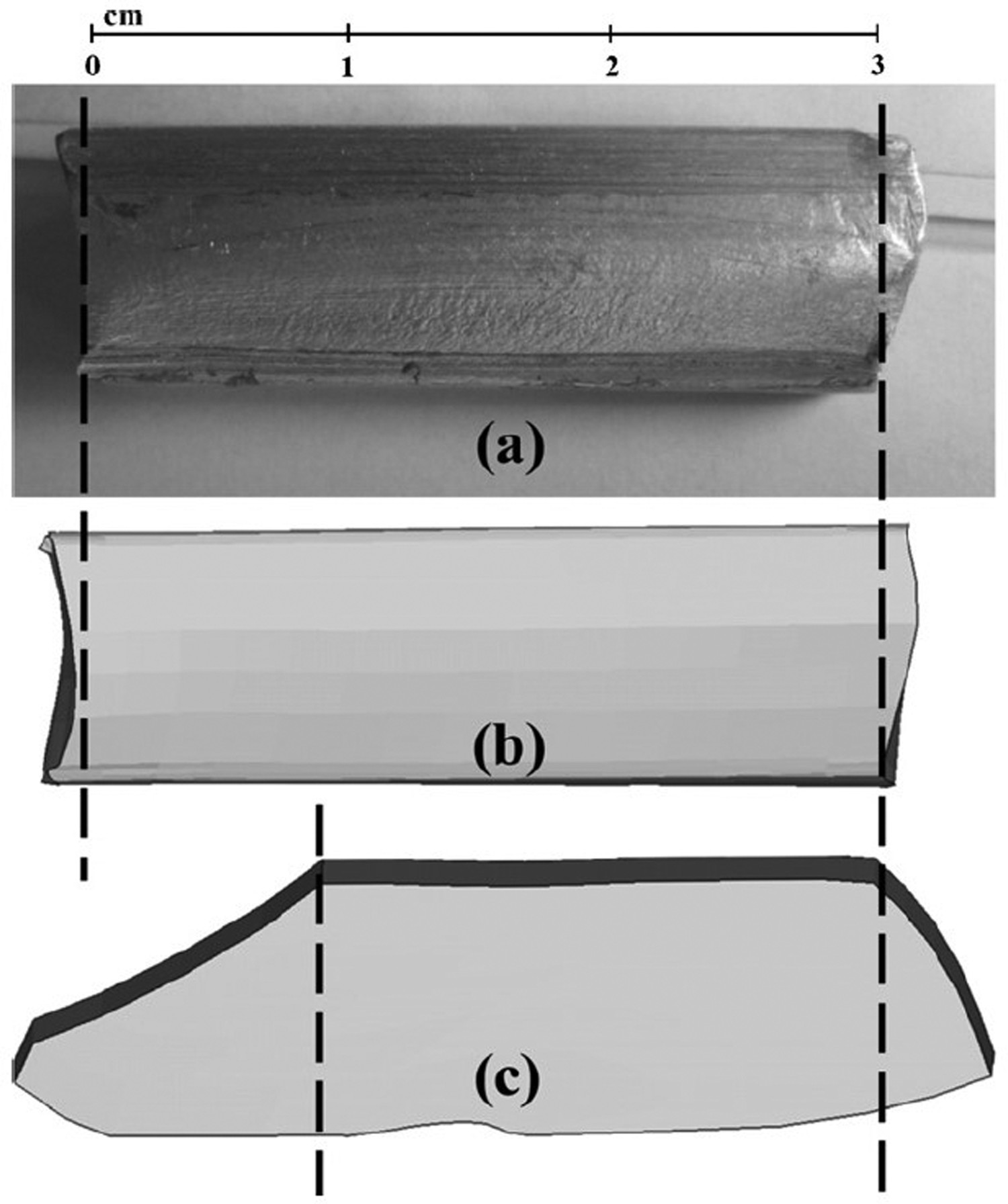
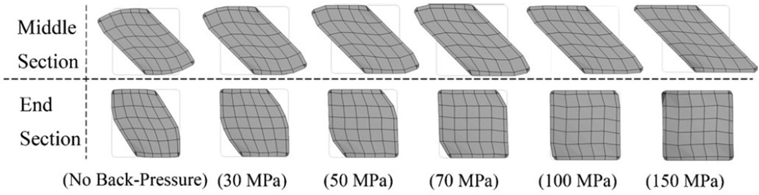
Backpressure and strain distribution
With almost no doubt, the distribution and magnitude of the imposed strain on the SPD processed sample differ from the theoretically anticipated one. For example, there are many articles showing that the effective strain is not uniform through the cross-section and even the length of the ECAP processed sample [45,46]. This situation could be moderated by the application of external pressure in the reverse direction of the movement of material in the die channel, known as backpressure [47]. Based on Figures 6 and 7, it can be seen that SSE is not an exception to this essence. The effect of back pressure on the cross-section of the specimen in the middle and final stages of SSE is shown in Figure 6 [18]. As it may be seen under nil or low back pressures, certainly, the material has not completely filled the extrusion channel, and complete deformation has not occurred. This issue, in turn, affects both the magnitude and distribution of the strain imposed on the specimen. Figure 7 represents the effect of different backpressure values on the variation of shear strain at the centre of a cross-section from the beginning to the end of the deformation channel (M–N) obtained by FE simulation compared with the theoretical results of Equation (1). Before proceeding to the interpretation of these curves, following point should be declared. As stated in section ‘Distortion Angle Profile and Optimization of linear die profile’, the original distortion angle profile was second-degree polynomial; hence
 and therefore
 are seen to be non-linear functions of the position along the channel length. Now, as it can be seen in Figure 7, for each magnitude of backpressure, the corresponding curve reaches a maximum at the middle of the channel and thereafter decreases to a certain value at the end of the channel. These curves present just mathematical shear strain to show the phenomenon of strain reversal in this process, which is very important in microstructural evolutions and will be discussed in the next section. Until then, from these curves, it can be interpreted that during the second half of the channel, the direction of the shear strain is completely reversed. The specimen attains its original shape by this reversal, yet, this change of direction would not result in cancelling the stored shear strain. In contrast, the imposed shear strains by the two halves of the channel would accumulate. From the viewpoint of the effect of backpressure, it can be seen that for the insufficient magnitudes of the internal pressure, the imposed strain on the specimen would be less than that of the theoretical prediction. This is due to the fact that material has the freedom to deform along the extrusion direction, and such a tendency should be hindered by an appropriate amount of backpressure. By exerting low backpressures, the material would not fill the channel completely, and the deformation would not be limited to the plane perpendicular to the extrusion direction.
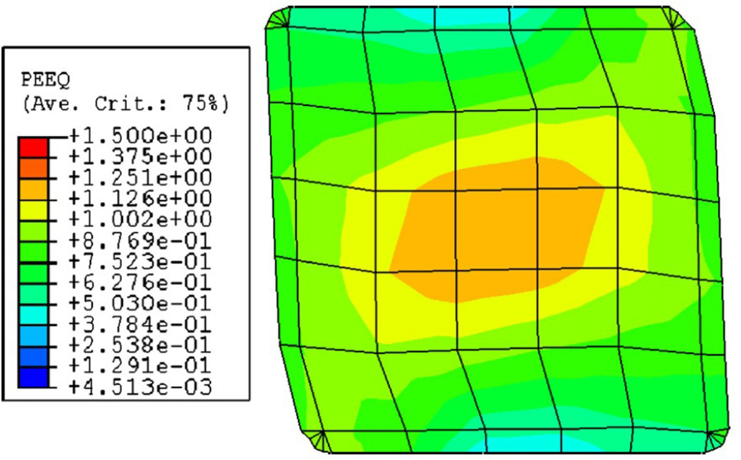
Thus far, the distribution of strain along the channel length is discussed. For the distribution of the effective strain in the cross-section of the specimen after SSE, FE simulation shows that the equivalent strain distribution is symmetrical and higher at the specimen's centre, slightly decreasing toward the periphery (Figure 8). This trend is quite different from what is reported for the TE processed samples in which a severe strain gradient exists through the cross-section. Additionally, higher strains are observed to be imposed on the peripheral regions in a decreasing manner towards the central point [48]. Certainly, as shown in Figure 6, the amount of backpressure affects the final shape and, consequently, the magnitude and distribution of strain at the cross-section. As the backpressure increases, the material fills the channel, and the deformation becomes completed. According to the experimental and simulation results, the required back pressure depends on the material's flow stress, for example, 170 MPa [30] for copper and 150 MPa for aluminium [18]. The required backpressure may be provided by either [1]:
Using two punches, one for performing the extrusion and the other for providing the required backpressure. Using the required pressure for the extrusion of a viscous medium placed ahead of the exit channel as back pressure. Increasing the level of friction at the exit channel. FE simulation result of the distribution of equivalent strain at the cross-section of specimen processed by one pass of SSE with 100 MPa of backpressure [18].
Using two punches requires an advanced facility to have two controllable horizontal and vertical punches, which limits this method's applicability. On the other hand, increasing the level of friction at the exit channel could not be considered a long-lasting solution. The reason is that besides the adverse effects of the friction on the surface of the processed samples, after processing several specimens, the frictional condition would alter at this location due to wear. During the investigations on SSE, the required backpressure is provided by a modified approach as follows. Practically, the final few millimeters of the outlet channel were machined to be slightly smaller than the initial dimensions of the specimen, comparable to the elastic expansion of the sample after ejection. Such a design first provided the required backpressure and second prevented the samples from becoming thicker than the inlet channel, which made it easier to repeat the process. On the other hand, multiple samples were loaded into the die. In this situation, the required extrusion load of the front sample will be provided by the rear sample. The developed contact stress between these two specimens, therefore, yields the required backpressure on the rear sample.
Processing routes
While different parameters can affect the properties of materials processed by this method, the rotation of samples between consecutive passes (known as the processing route) can be considered a simple procedure to manipulate the final microstructure [49]. These different processing routes would result in a point within the sample experiencing different strain paths during each pass, which in turn, affects the microstructure of the processed material. ECAP, in this subject, is the most studied process. Several reasons are stated to be responsible for such a difference in the final microstructure attained by different routes of ECAP, including the angular range, whether the route is redundant or not, and whether the deformation takes place on one of the orthogonal planes or on all of the three orthogonal planes [50,51]. One of the effects of rotating the sample between each consecutive pass is the resulting change in the relative orientations of each grain with respect to the shearing direction, which affects the active slip systems. This results in a complex regime of grain rotation, dislocation interactions, and sub-cell formation and, therefore, more enhanced microstructural evolutions [50]. The effect of orientation of slip systems relative to the shear plane on microstructural development during the ECAP is well studied in the following references [52,53].
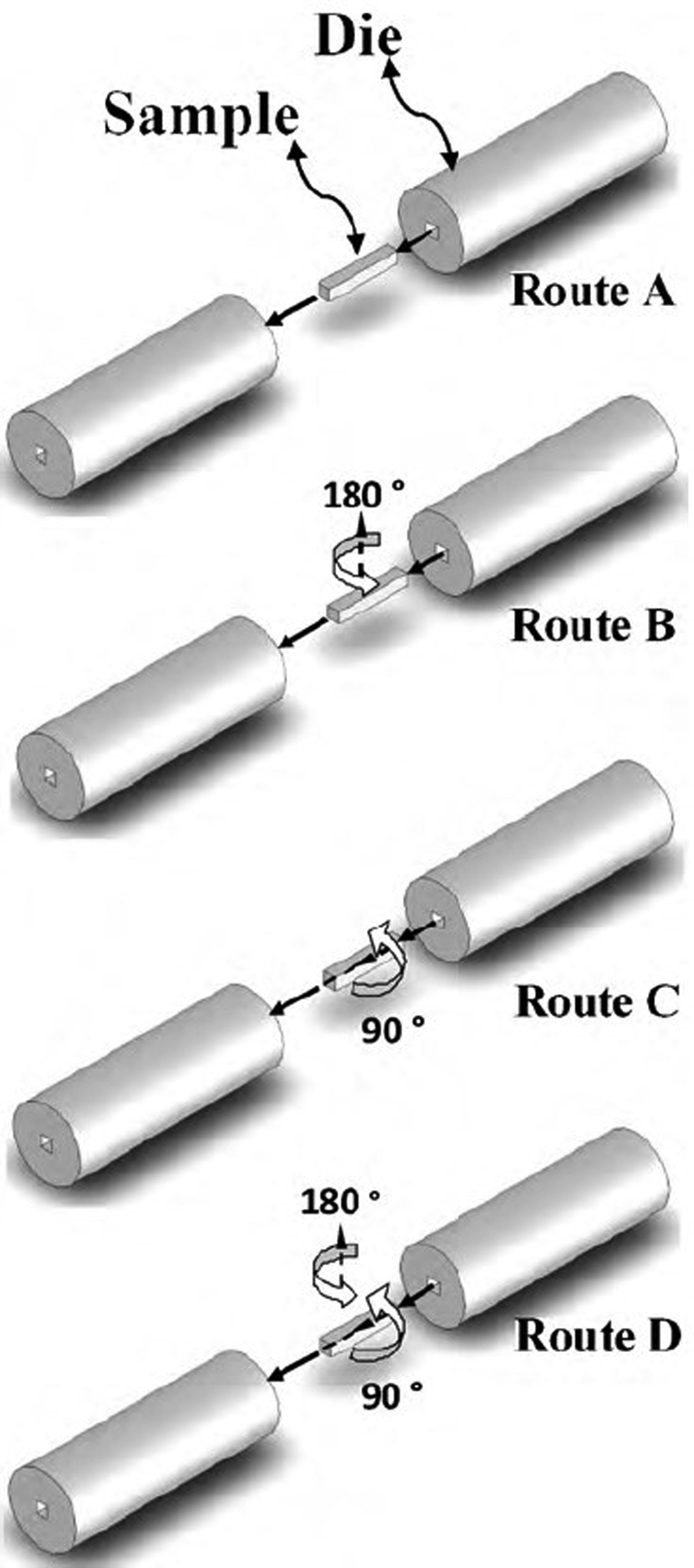
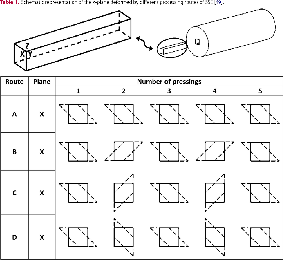
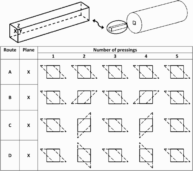
The processing routes that may be defined in SSE are presented in Figure 9 as routes A, B, C, and D, and the shearing pattern for each route is shown in Table 1 [49]:
Route A: in this route, the specimen will be inserted in the die without any rotation between consecutive passes. Route B: in this route, the specimen will be reversed between consecutive passes by rotating it by 180° about an axis normal to the extrusion direction. Route C: in this route, the specimen will be rotated by 90° about the axis parallel to the extrusion direction. Route D: in this route, the combination of routes B and C will be applied. Spatial representation of different processing routes of SSE [49]. Schematic representation of the x-plane deformed by different processing routes of SSE [49].
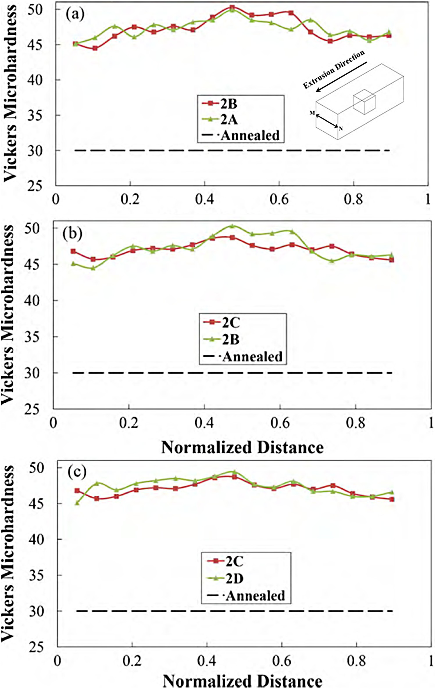
The shearing path of routes A, B, C and D are illustrated in Figure 10. In this figure, the shear strain imposed on a material point is traced as it experiences four consecutive passes of SSE with the indicated routes. It can be seen that these shearing paths are different from the perspective of (i) the amplitude1 and (ii) the planes on which the shear strain is imposed. Based on the aforementioned discussions, it is logical to assume that different microstructure and mechanical properties would be obtained by each route. In this manner, routes C and D of SSE extend the shear strain to occur on two orthogonal planes, and hence, a more uniform microstructure is expected to be obtained by these routes. Thus far, unfortunately, no investigation is directed to exactly check these expectations by means of TEM micrographs. However, the variation of the hardness is investigated after two passes of SSE performed by different routes, and the results are reported in Figure 11. As can be seen from Figure 11, routes C resulted in an improvement of strain distribution uniformity compared to route B. These findings are in accordance with the expectations mentioned above.
The shear strain path in four different routes of SSE. Comparison of the values of microhardness along the line M–N (introduced in the insert) for Al sample processed by two passes of SSE with different routes [49].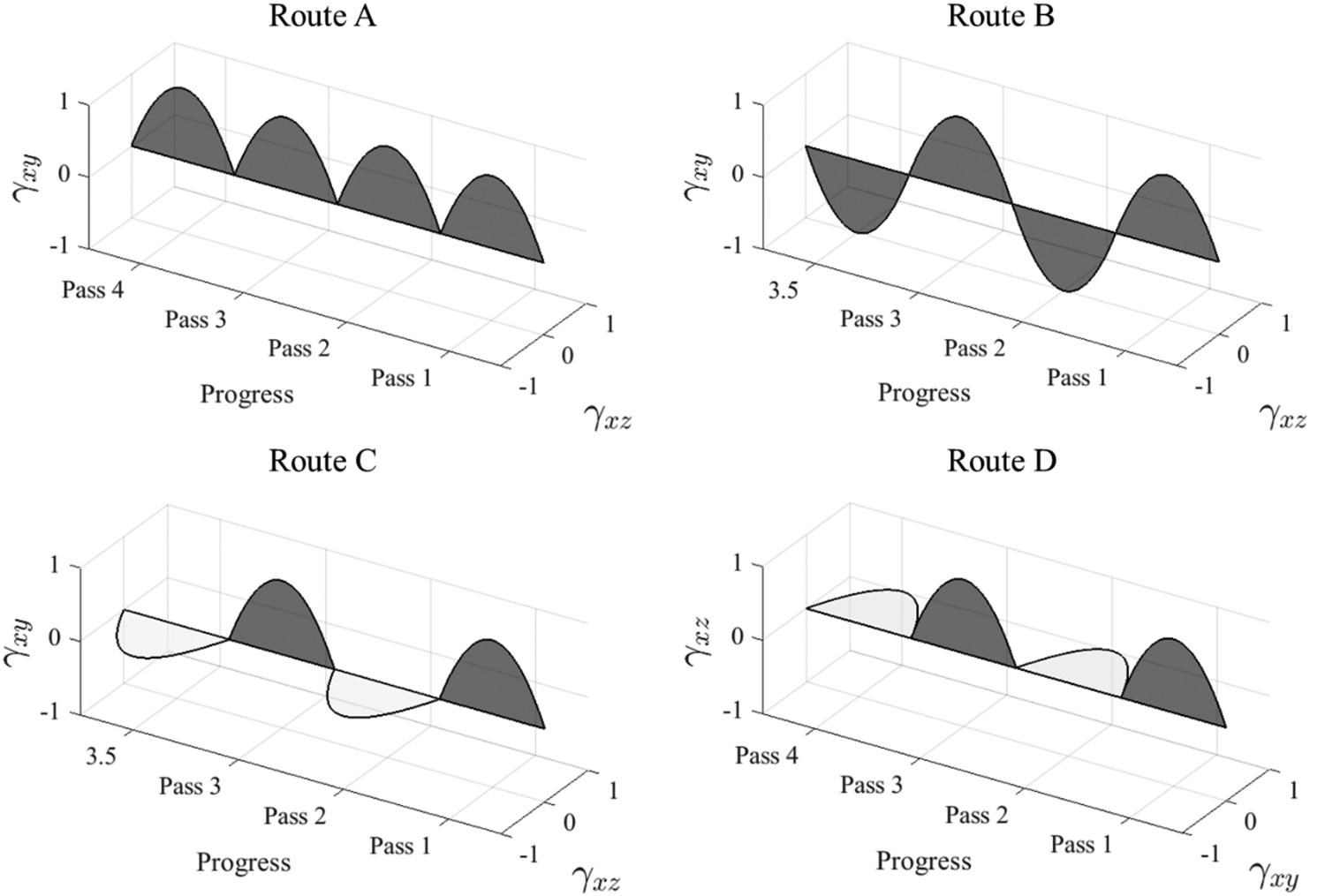
Processed materials
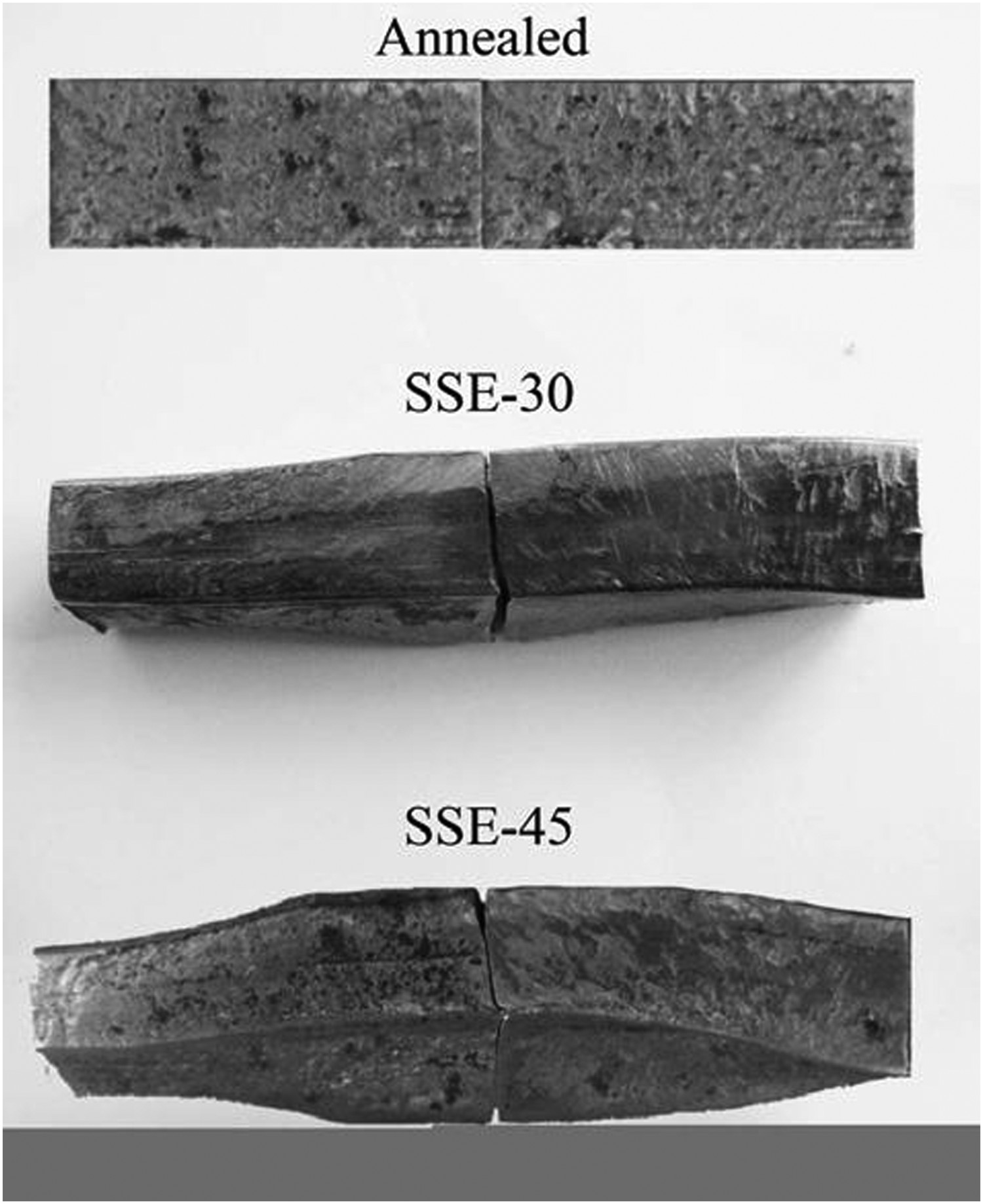
The early experiments on SSE were performed on aluminium as a material model to investigate mechanical and metallurgical aspects of this technique. However, the final achievable grain size was not less than about 1 μm. The reason for these observations could be explained based on the following well-established rule: In the low stacking fault energy materials, such as aluminium, the dynamic balance between the generation and annihilation of dislocations would be established at high energy levels, and therefore, smaller cell sizes may be achieved [54]. On the other hand, since these cells then gradually transform into grains with high-angle grain boundaries, the final grain size would be smaller [55]. In the next phase of studies, copper samples were processed by SSE, and a smaller grain size was achieved due to the low stacking fault energy of this metal. Subsequently, other metals such as twinning-induced plasticity (TWIP) steels, magnesium, and magnesium alloys were tested. Few reports show that severe plastic deformation of relatively high-strength materials such as steels is difficult due to the segmented flow. For example, it is observed that the segmentation in such steels would occur after one pass of ECAP due to flow localisation (Figure 12). However, it is shown that TWIP steels could be processed successfully by SSE without segmentation [23]. This is attributed to the fact that SSE has a relatively larger deformation zone, and shear strain is imposed gradually through the channel. Hence, it would be possible to deform such steels without producing any segmentation (Figure 13). The gradual deformation is the secret to this process's success in deforming hard-to-work materials. Here, another capability of this technique is revealed: the degree of the gentleness of deformation imposed on the specimen can be altered and designed without affecting the magnitude of imposed shear strain per each pass by changing the distorsion angle profile. This ability can even be applied in a more sophisticated manner: the gentleness may be designed based on the material's internal state, harsh at the initial stages of deformation, and mellow as material work hardens. This could be accomplished by the non-linear and non-symmetric design of the die. However, the severity of the imposed shear strain in each pass (and not only the total imposed shear strain) also plays a crucial role in the development of the desired microstructure [1]. In this regard, further investigations are required to prove that whether the proposed approach would result in the desirable grain refinement of the hard-to-work materials or not.
Segmentation of TWIP steel during deformation by ECAP [23].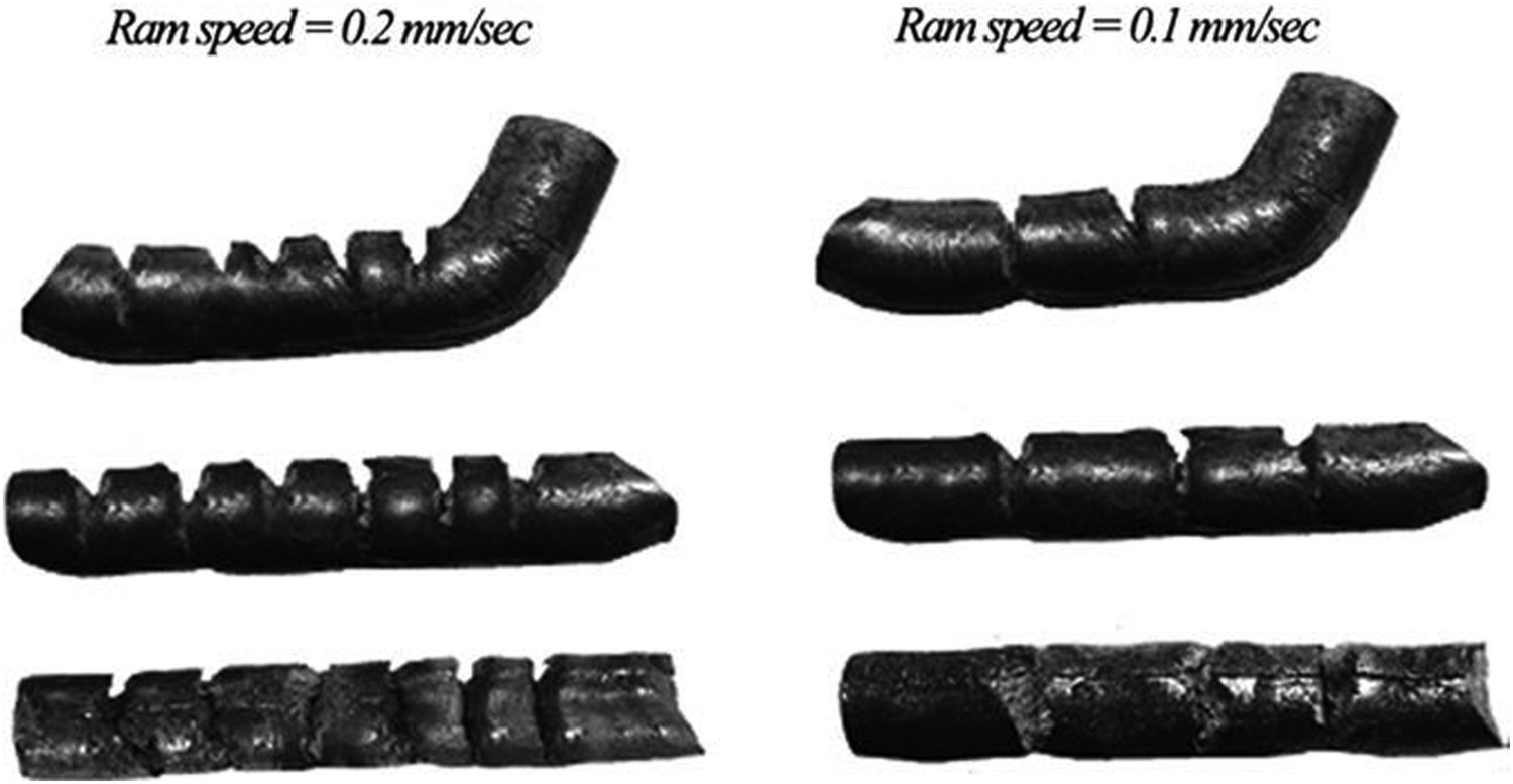
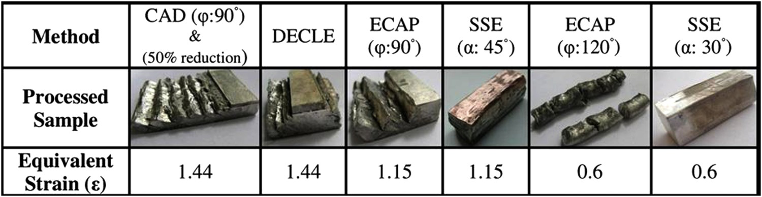
Subsequent research has shown that this technique is capable of deforming HCP metals such as magnesium at room temperature [19]. Figure 14 illustrates the macroscopic appearance of the as-cast samples processed at room temperature by means of different SPD techniques. As can be seen, the samples were processed by ECAP (
 ), Dual Equal Channel Lateral Extrusion (DECLE) [56], and Channel Angular Deformation (CAD) [57,58] are severely segmented due to the localised shear strain applied along the shear plane. This is due to the poor workability of magnesium as it is processed by these methods at room temperature. However, the sample processed by SSE (
 ) exhibits no significant segmentation compared to the ECAP processed sample. Again, this improvement might be attributed to the gradual straining of material by passing through the SSE deformation channel. It would be even possible to deform the material even more gradually by reducing the
 in the SSE process while maintaining the same deformation zone length [19]. Comparing the processed samples by SSE with
 and
and
 illustrates this point (Figure 15). Such a reduction of the
 resulted in the decrement of the applied strain from 1.15 for
 to 0.6 for
 . By this change in the
 , strain rate decreased as well.
Of course, magnesium workability did not allow for more than two passes of SSE to be performed at room temperature. Therefore, in another study, Gd was added to magnesium to improve its workability [22]. However, to continue the process to the higher stages, the temperature had to be raised (250–280°C) [59,60]. In this essence, one of the open subjects in this field is investigating the solutions to further extend the current achieved state of workability of magnesium and magnesium alloys to be processed by SSE at room temperature [61].
Thus far, the application of SSE has been mainly focused on the bulk metallic materials and production of UFG structures. However, as it is known, the SPD techniques can be used for other applications, such as mechanical alloying, powder consolidation, and even processing of ceramics [62]. On the subject of powder consolidation, recently, Qods and colleagues conducted an experiment on the processing of Al/Al2O3 composite using SSE. They demonstrated that consolidation of the mixed powder compact by SSE reduced the remnant porosity after sintering. High imposed strains, along with the reduction of the porosities, resulted in the increment of the ultimate shear strength, shear yield strength, and Brinell hardness number of the SSE processed samples [63,64].
On the other hand, in the field of mechanical alloying and especially processing of the ceramic powders, it does not seem that there would be much space for the processes such as ECAP or SSE as opposed to HPT. Two reasons can be enumerated for this:
After compression of the powder compact in the first stage of HPT, the processing volume between the HPT anvils will be almost closed, and there will not be a pathway for powder particles to leave this processing zone. On this basis, it is possible to impose high shear strains on the powders. On the other hand, during ECAP or SSE, it is unlikely that powder compact passes through the deformation zone and experiences the shear deformation, especially for the powder of materials with low ductility (e.g. ceramic powders). Instead, in this situation, the powder compact simply breaks and disintegrates. HPT is a continuous process in contrast to ECAP or SSE, and it is possible to impose the desired strain on the specimen without the requirement to remove it. In this situation, even if the powder compact successfully passes through the deformation zone in ECAP or SSE, there is a high possibility that the processed powder compact to break during removal or when it is inserted into the die for the next pass.
Study of the development of microstructure by SSE
As previously mentioned, one of the important aspects of SSE is the reversal of the shear direction after passing from the first half of the deformation channel toward the second half. This inherent geometrical characteristic by itself leads to the strain reversal effect in this process. In the attempt to capture the effect of strain reversal in SPD processes, Orlov et al. conducted the HPT process on high purity Al by two regimes of continuous (monotonic) straining and step-wise (non-monotonic) straining. In the latter, after 12° of rotation, the direction of rotation was reversed. They reported that the non-monotonic regime retarded the production of the UFG structure without any significant advancement in the grain refinement when compared to the monotonic straining. However, they predicted that the final product would have more ductility and stability because of the lower developed dislocation density as a result of the annihilation of some dislocations due to the reversal of the strain [65].
TWIP steel sample processed by SSE with maximum distortion angles of 30° and 45° [23]. The appearance of Mg samples processed with different SPD techniques at room temperature and equivalent imposed strains [19]. Magnesium samples after (a) two passes of SSE with
 and (b) one pass of SSE with
 [19].
[19].
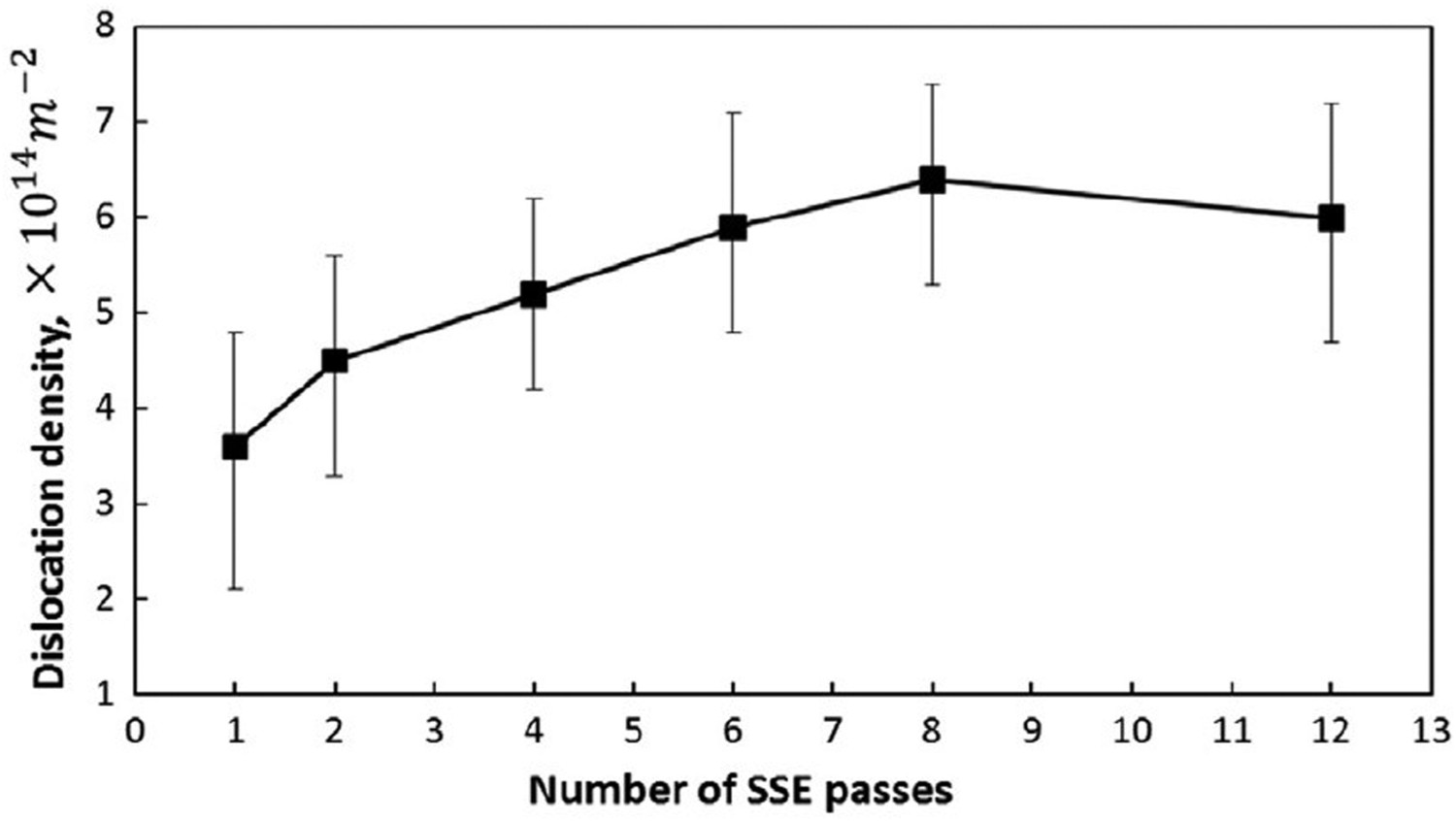
The strain reversal effect could be observed in the SSE by observation of the change in the dislocation density of copper, as shown in Figure 16. The gradual decrease in the dislocation density in the second half of the channel indicates that some of the dislocations are annihilated by the Bouashinger's-like effect [27]. In other words, the dislocations in the back of the pile-ups generated in the first half of the channel will disappear by changing the shear strain direction in the second half of the channel. This unique characteristic is useful for producing nanostructured materials with lower dislocation density and, subsequently, more stability. However, as shown in Figure 17, the dislocation density increases pass by pass and decreases in the 12th pass by the continuous dynamic recrystallisation mechanism [66].
Evolution of the dislocation density through the length of the channel for the first pass of SSE [27]. Evolution of dislocation density by each pass of SSE [66].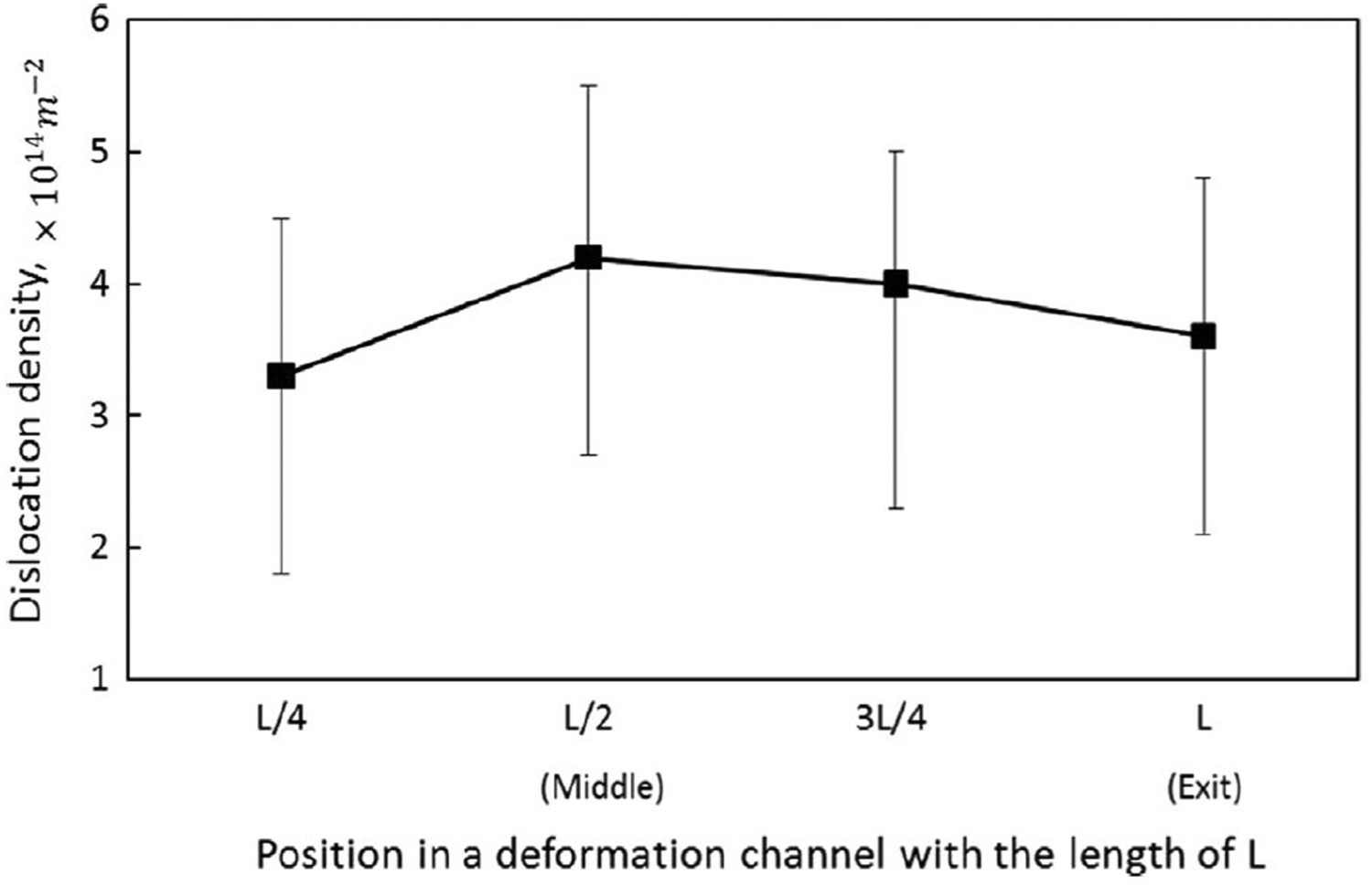
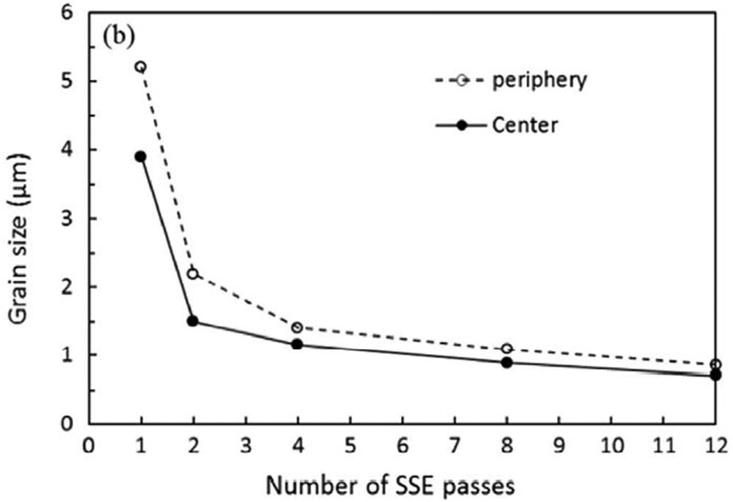
In the next phase, more in-depth research was carried out on copper [28]. The EBSD 3D images of copper in Figure 18 show the potential of this process in manufacturing bulk nanostructured materials. A close look at these images indicates that the final grain size (about 700 nm) obtained after the 12th pass equals the width of the elongated cells or subgrains array formed after the 1st pass. This is in complete agreement with the fundamental research done on single crystal and aluminium polycrystals [67]. Besides, it can be seen that the directions of the cell structures that are formed in different grains have no relationship with the geometry and the direction of the deformation process. It is well established that the subgrains line up according to the crystallographic directions in the grains, and the grains themselves align according to the maximum principal strain directions [50]. The latter in this process will be examined in future sections. Figure 19 shows the trend in grain refinement and the slight difference in grain size in the centre and periphery of the cross-section of the sample, according to the strain distribution. At this point, while the subject of grain size is brought up, it is worthy to mention that a recent investigation showed that SSE is more efficient in achieving a fine-grained homogenous microstructure with higher shear strength as compared to ECAP [59].
3D EBSD images of copper specimen processed by SSE with different numbers of passes [28]. The grain size at the centre and periphery was measured on the plane perpendicular to the extrusion direction obtained for a pure copper sample as a function of the number of the SSE passes [28].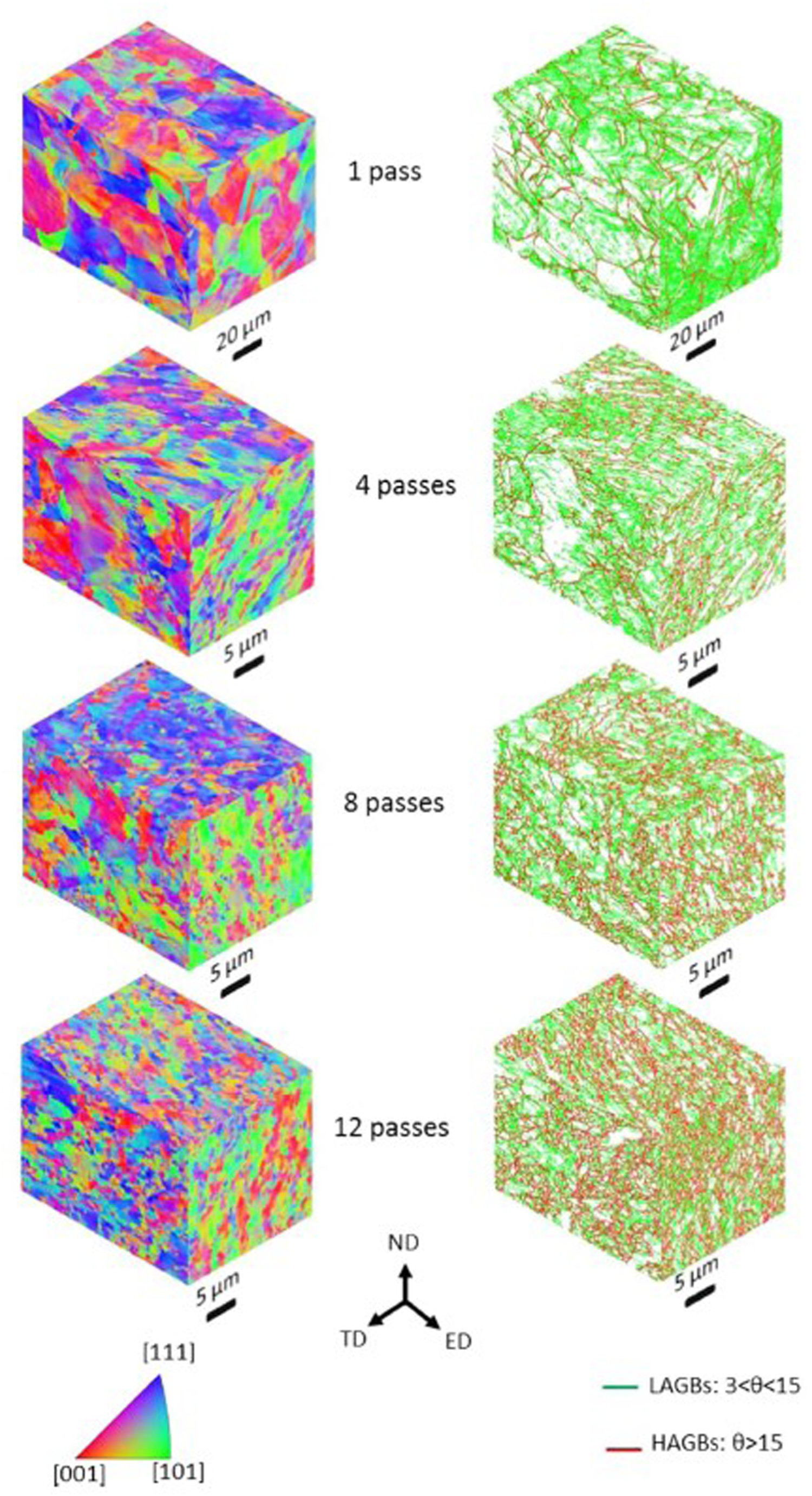
Correlation between special microstructural features and mechanical properties
Weak texture and effect of the average Taylor factor
Figure 20 shows the variation of yield strength and ultimate tensile strength (UTS) at the centre and the periphery of the SSE processed copper specimen [68]. As can be seen, both yield and UTS are increased during the first few passes, and the values of yield and UTS at the centre are higher than at the periphery. The increase in the yield and UTS can be attributed to the generation of dislocations and the hardening due to well-known dislocation-related phenomena. The higher values of yield and UTS at the centre compared to the periphery are due to higher strains imposed on the central regions compared to peripheral regions (Figure 8). Another aspect of Figure 20 is that after about 4–8 passes, the yield and UTS are decreased; the same results are observed in HPT by an increase in straining. As well discussed in [4], these results may be attributed to the decrease in dislocation density due to the formation of new high-angle grain boundaries at the expense of the generated dislocations. However, the observation that the maximum values (yield strength and UTS) are not equal in the centre and the periphery does not seem justifiable. In other words, since the theoretical accumulated strain of the periphery reaches that of the centre but in further passes, it usually is expected that the yield strength and UTS in the periphery reach that maximum of the centre, yet with a delay. This ambiguous observation can be well explained as follow: the experienced mode of deformation is not the same for the centre and periphery, partly due to the special geometry of the process and partly due to the contact of material at the peripheral region with the die, which makes the strain regime to deviate from simple shear. This difference in the deformation mode would result in the difference between what may be called the weak texture of the centre and the periphery.
Variation of yield strength and UTS for the centre and the periphery of the copper specimen undergone SSE for the different number of passes [68].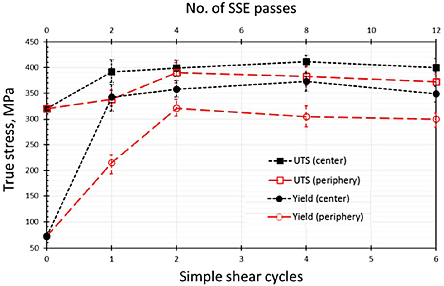
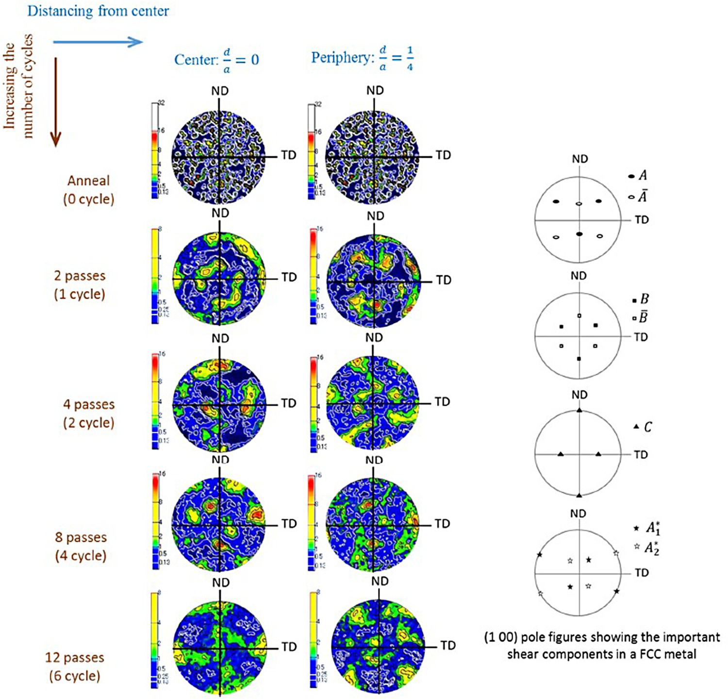
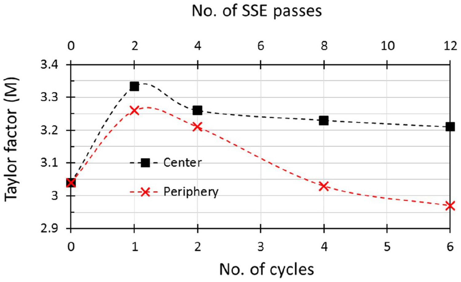
Figure 21 demonstrates the (1 0 0) pole figures for the centre and the periphery for different passes. As can be seen, there is not any strong texture formed in the centre or the periphery even after 12 passes. However, at the same time, the distribution of the orientation of the grains is quite different between the centre and the periphery. The mechanical behaviour and strength of each grain within a crystal aggregate could be described based on its Taylor factor, which depends on its orientation relative to the global coordinate system of interest. In this regard, each grain would have a specific Taylor factor. However, it is possible to represent the strength of a test volume of material as a function of the average Taylor factors of the grains within that volume through the following equation.
Illustration of (1 0 0) pole figures of copper specimens for several passes of SSE at the centre and the periphery [68].
Optimum mechanical properties and bimodal microstructure
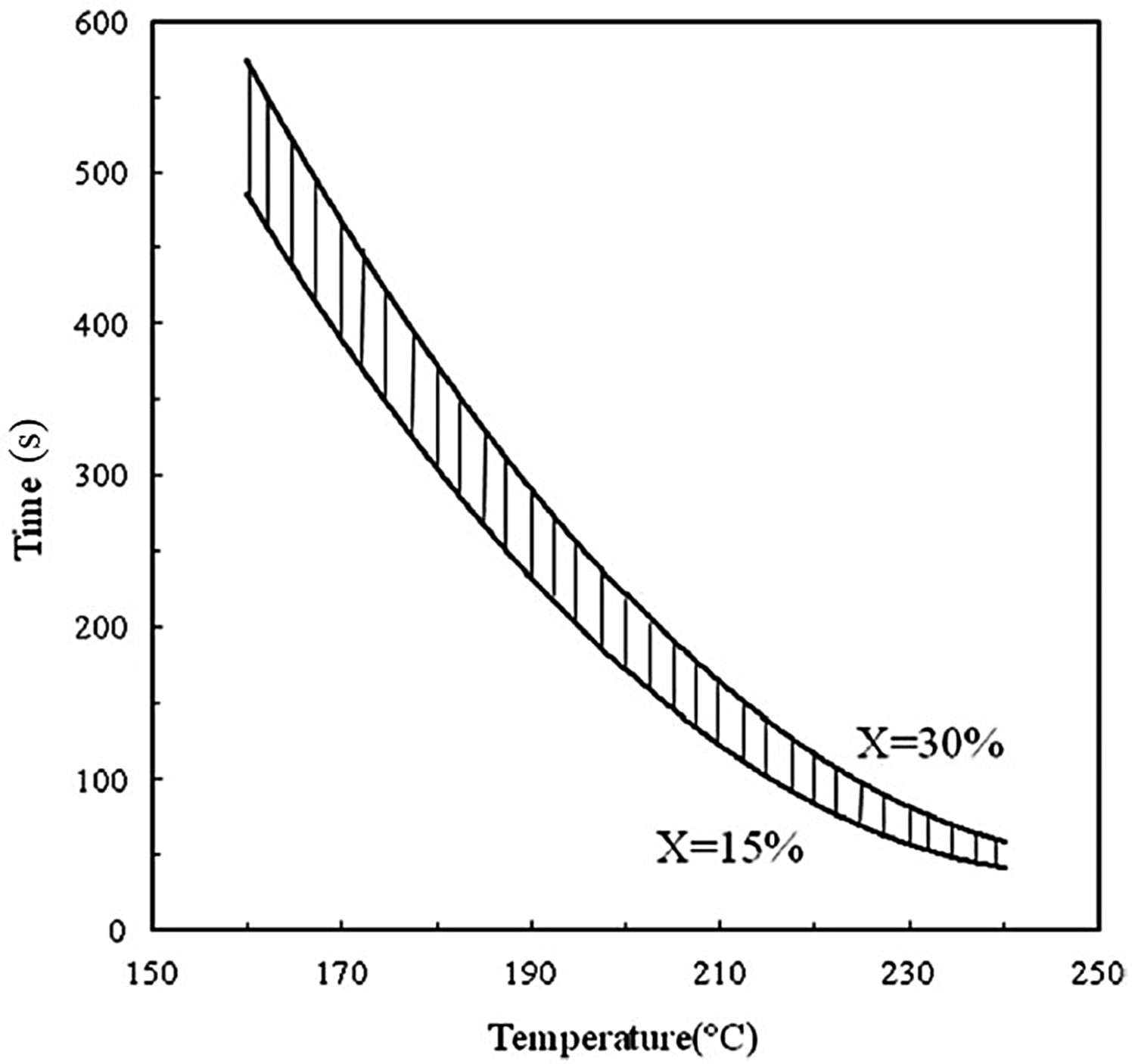
One of the major drawbacks of the SPD products is that they lose their ductility with increasing strength in the initial stages of straining [69,70]. The previous investigations showed that the condition would be improved after very large deformations are imposed on the material (after 25 ECAP passes on copper samples), where a bimodal structure develops [71,72]. It is possible to establish such a bimodal structure by application of a special heat treatment process called partial recrystallisation. In this situation, less energy [73] would be required compared to continuing the plastic deformation to such high strains. The work in this field showed that there would be a combination of suitable annealing time–temperature ranges to obtain optimum mechanical properties where both UTS and elongation of the SSE processed copper specimen increase [26]. A typical shear punch test result in Figure 23 shows the impact of partial recrystallisation on obtaining the optimum mechanical properties. The softening fraction band in Figure 24 shows the prescribed optimum annealing time–temperature ranges for the case of severely deformed copper after 6 passes of SSE (the strain of 6.9).
Stress vs. Normalised displacement curve obtained by shear punch test performed on a copper sample which is deformed by 6 passes of SSE and then subjected to partial annealing at the temperature of 180°C for different times, the fraction of recrystallisation is denoted by X; note that for X = 3% both the UTS and elongation are increased [26]. Representation of the annealing time–temperature band to obtain optimum mechanical properties [26].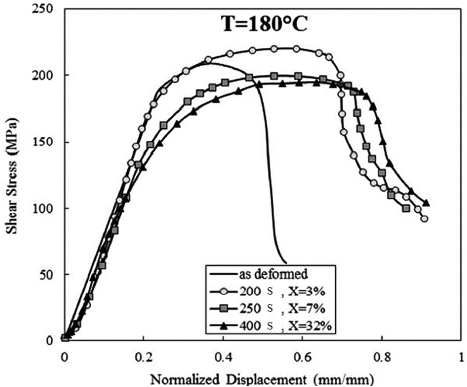
Computational investigation of the development of microstructure
Along with the numerous experimental investigations on the microstructural evolution of materials processed by SSE, the change in the microstructure is also studied by numerical approaches. The development of bimodal structure is studied by the Monte Carlo method [74]. In another study, the evolution of texture by SSE is studied by means of CPFEM [29]. Figure 25 represents the predicted and experimentally investigated texture of SSE processed copper specimen at processing lengths of 0.25L, 0.5L, and 1L, which shows good agreement between simulation and experimental results.
Comparisons of (1 0 0) pole figures representing texture obtained by CPFEM (prediction) and experimental investigations [29].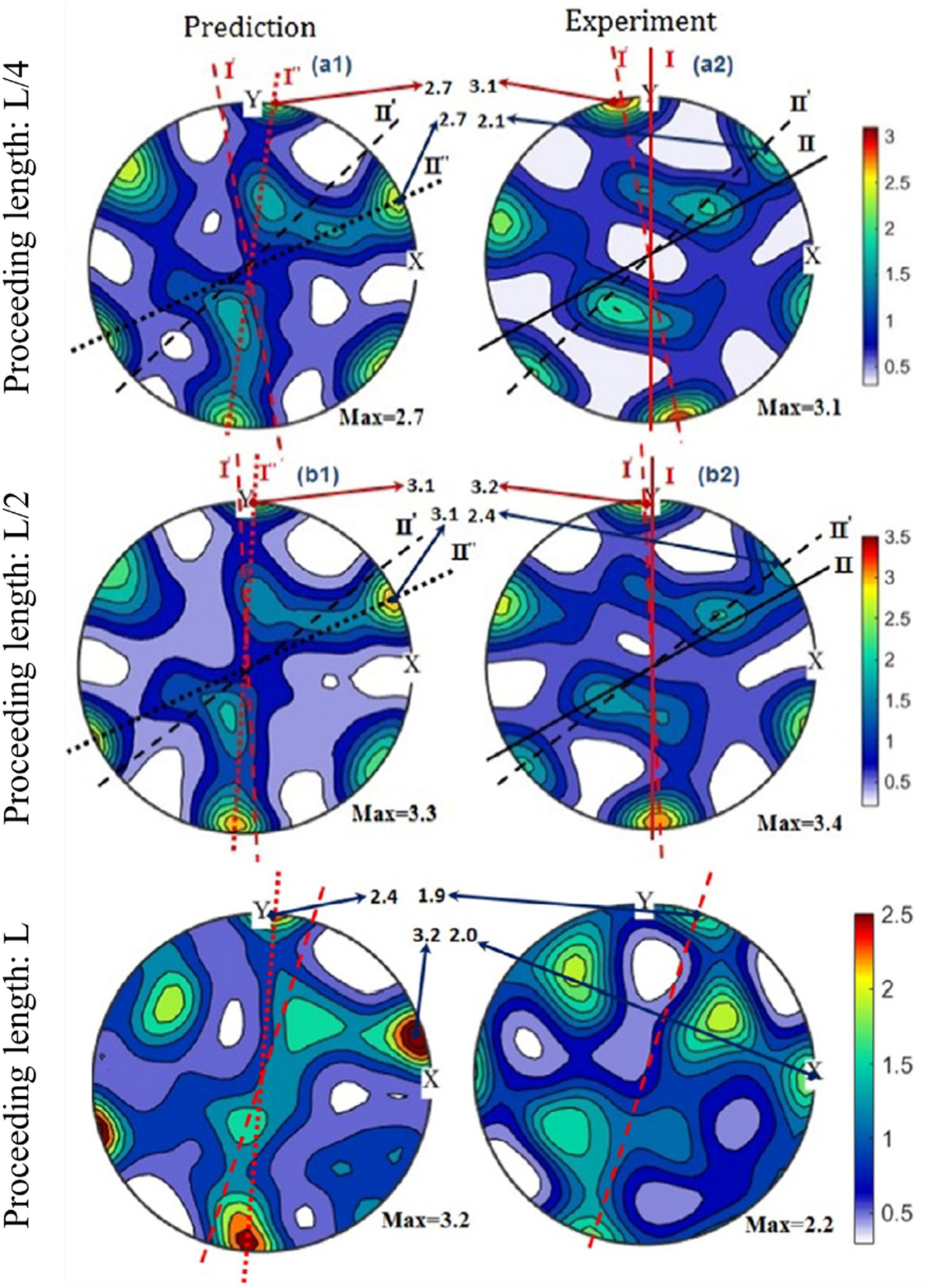
Circular simple shear extrusion
General design and advantages
The most recent development of SSE was to design the process with a circular cross-section [31,32]. Figure 26 shows how to bring out a circular deformation channel from inside a square one.
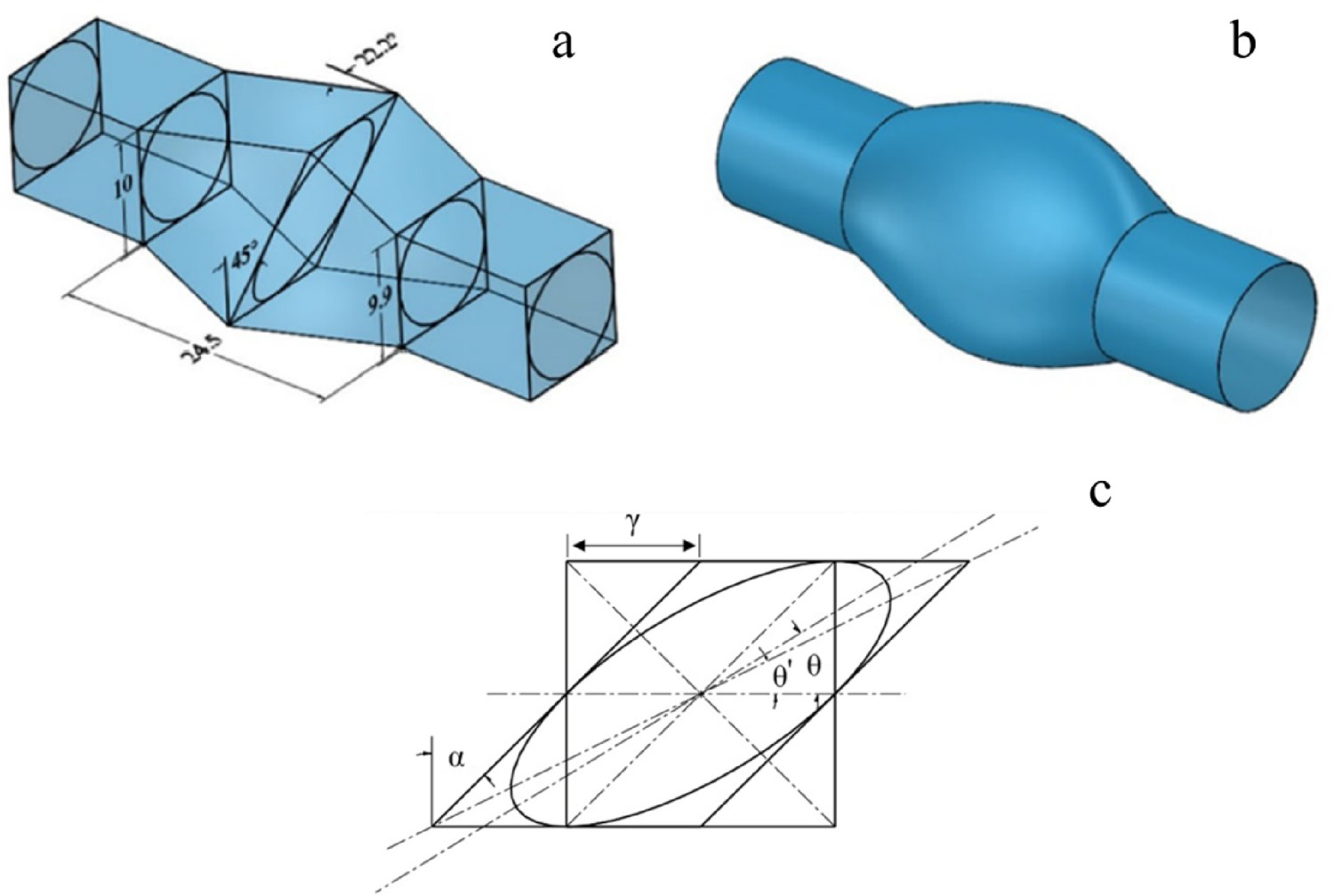
The inclination of the major axis of the ellipse and the major axis of the parallelogram may be related to each other through Equation (6).
It is clear that the circular cross-section is a favourable shape in most industrial applications. Also, FE simulations showed that the accumulated strains are closer to theoretical ones in CSSE [33]. In addition, because cylindrical specimens have less surface area than prismatic ones, the friction force in the CSSE process would be less than that of SSE. Hence the total force required to complete CSSE would be lower than that of SSE. Another cause of such reduction in force is the smaller cross-sectional area of cylindrical samples for the same diameter.
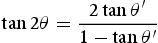
The simulations and experimental results have shown that the CSSE process fills the die with less backpressure than SSE with a square cross-section [32]. Figure 27 shows the aluminium samples before and after the first pass of CSSE with and without backpressure.
Aluminium samples underwent CSSE for one pass with and without backpressure [33].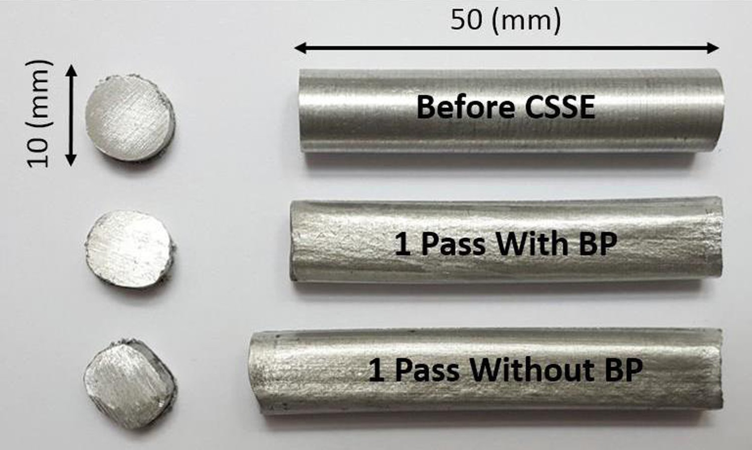
The die stress analysis in Figure 28 shows that the region with maximum principal stress is located at the SSE die corner, a critical fatigue location. However, in the CSSE die, the values of maximum principal stress are lower; also, a more uniform distribution of stress could be observed. Therefore, it is expected that the CSSE die has a longer lifetime than SSE die. Hence, this new geometry will provide more potential in terms of industrial applications.
Distribution of maximum principal stress exerted to the die by material for (a) SSE and (b) CSSE [32].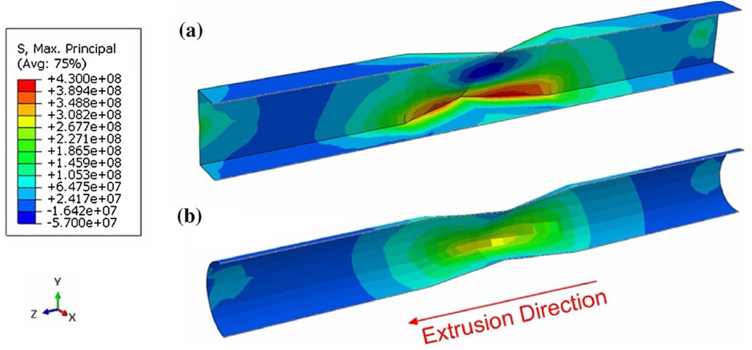
CSSE as a move toward the ideal regime of simple shear
Besides all of the aforementioned advantages of CSSE, one fundamental point needs to be discussed. As explained by V. Segal, the simple shear corresponds to the situation where the strain rate along with one of the slip lines (α or β) is zero. In SSE, this particular velocity field is developed through the imposed geometrical constraints by the specific design of the die channel rather than by applying the shear stress. It is delicately pointed out by V. Segal that this condition would result in the deviation of the strain field in SSE from that of ideal simple shear [14]. This is partly due to (a) the friction at the faces of the channel opposing the movement of material and (b) the lack of constraints on the deformation of the material in the extrusion direction (normal to the cross-section). The latter can be eliminated by implication of proper level of backpressure, while the former is the main subject of CSSE. By designating SSE with the circular cross-section, the total frictional area decreases; hence near ideal state of strain may be achieved.
Applications
Biomedical materials
Figure 29 shows the successful processing of a magnesium rod by CSSE at 250°C for biomaterial applications. Magnesium is a lightweight material with high specific strength, biocompatible, and biodegradable with nil side effects on the human body. Nevertheless, the low workability of this metal is a major drawback both for use in the human body and development. Numerous researches are done to improve the ductility of magnesium by alloying and manipulation of texture by thermomechanical processing. Rare earth elements are promising alloying additions, which in trace levels could affect the workability and the developed texture of processed magnesium alloy.
Successful processing of magnesium specimen by CSSE.
The effect of Y, Gd, and Nd alloying elements on the workability and the developed texture of Mg alloys for biomaterial applications processed by CSSE is under investigation. It is part of our future research plans.
Application in microforming
Practical applications are the final goal of any development in materials science and engineering. Therefore, this section explains the use of severely deformed copper in microforming to show one of the applications of the bulk nanostructured materials in advanced processing. The use of materials in microscale structures is challenging. As the grain size becomes comparable to the specimen's size, it makes the mechanical and geometrical behaviours unpredictable by classical plasticity theories. The change in the material's behaviour with the grain size to specimen size ratio is called the size effect. It is well established that to provide reproducibility in the production of small parts, a large number of grains are needed to be present in the specimen [76,77]. Therefore, if the specimen is on a microscale, the grains must be of nano-scale to eliminate the size effect, indicating one of the applications of nanostructured materials in microforming processes. Research in this area has led to the introduction of a new model describing the plastic behaviour of grains in an aggregate, named the combined Hill–Taylor model [78]. Simulation of the micro-compression test of specimens composed of a limited number of grains demonstrated that as the grain size becomes smaller than the specimen size, the final geometry tends to be regular [79].
Advantages and disadvantages of SSE
Based on the aforementioned discussions, the following advantages could be enumerated for the SSE and CSSE:
Lower wasted material: it is shown that processing of material with SSE results in lower geometrical irregularities compared to ECAP. These irregularities, such as the specimen's tail after ECAP, must be machined before the next pass, and after several passes, a considerable amount of material would be lost. More homogeneous strain: it is shown that compared to processes such as HPT and TE, SSE (like ECAP) results in a more homogeneous distribution of effective strain in the cross-section of the specimen. Processing of hard-to-work materials: It is shown that due to the inherent characteristic of SSE, severe strains are imposed on the specimen gradually. This gradual deformation makes SSE more efficient in deforming materials with low ductilities, such as magnesium or TWIP steels, compared to ECAP. Processing routes: SSE, like ECAP and in contrast to HPT, has four processing routes which make it possible to achieve various final microstructures with the same die.
On the other hand, the disadvantages of the SSE and CSSE include:
Retarded final UFG state: As stated previously, the strain reversal effect which prevails in SSE is expected to result in a more internally stable microstructure. However, this phenomenon may retard the development of the UFG state as compared to SPD techniques such as ECAP. Fabrication: Our experience with many SPD techniques showed that fabrication of SSE and specially CSSE die is somehow more tricky than that of ECAP, for example. However, since the fabrication of the die is just a one-off task, this would not limit the effectivity of SSE and CSSE. Discontinuity: As stated earlier, techniques such as ECAP and SSE are discontinuous, which means that the specimen must be removed from the die for the application of higher strains by the subsequent passes. This characteristic of SSE limits its applicability for the processing of ceramic powders or mechanical alloying purposes.
Further work
In addition to the direct use of SPD products as ultra-strong materials, these products have other characteristics which gained them much interest in some state-of-the-art industrial and research applications. Currently, the following characteristics and applications of the SSE processed materials are under study and planned to be further investigated in the future:
Hydrogen storage: Today, it has been proven that SPD methods are very effective in increasing the hydrogen storage capacity and kinetics of hydrogen sorption and desorption due to the increase of lattice defects such as grain boundaries and dislocations. Therefore, hydrogen sorption and desorption kinetics of magnesium alloys are under consideration. Superplasticity: It is well known that one of the most important criteria for superplasticity is the small grain size. Therefore, the investigation of the superplasticity of SSE processed materials is one of the main future goals. Biomaterials: Magnesium is a candidate material for application as a biomaterial; however, its low ductility and relatively low strength limit its applicability. These limitations may be well approached by the processing of magnesium by SPD methods to produce a nano-scale microstructure. In this regard, investigation of the effect of rare earth elements on the workability of magnesium to be further processed by SSE at lower temperatures is under consideration. Thermal stability: Due to the high energy of UFG products, one of the most fundamental properties of these materials is their thermal stability. Therefore, the study of this property is another future goal. It is predicted that due to the phenomenon of the strain reversal in SSE, the processed materials by this technique show better thermal stability than those processed by other SPD products. Microforming: This is also an important research field today. The most important issue in this regard is the phenomenon of the size effect. The use of UFG materials leads to the solution of the problems associated with this effect.
Conclusion
In this paper, different aspects of simple shear extrusion as an efficient technique for producing bulk nanostructured materials are reviewed. Important points of this study can be concluded as follows:
In this process, simple shear, which is the ideal deformation mode for microstructural evolution, is dominant. This process results in a lower wasted material compared to equal channel angular pressing. The electron backscatter diffraction and transmission electron microscopy results confirmed the ability of this process to produce bulk nanostructured materials. The investigations on twining-induced plasticity steel and magnesium showed that simple shear extrusion is a useful technique for processing hard-to-work materials. That is believed to be due to the gradual deformation, characteristic of this method. This process is analysed by the upper bound theorem, and based on that, the forming load and optimum channel length could be determined readily. Four routes are defined for SSE, which may result in different final microstructures. It is discussed that route C, which consists of 90° rotation of specimen about extrusion direction, would be the best route for grain refinement. The occurrence of the strain reversal phenomenon in this process may retard the formation of the final ultrafine-grained state. However, it is believed that this characteristic, in turn, yields a more stable final microstructure. Circular simple shear extrusion, a variant of simple shear extrusion with a circular cross-section, yields a more uniform strain distribution. The circular simple shear extrusion also has more potential in terms of becoming industrial. One of the most important applications of simple shear extrusion and circular simple shear extrusion can be summarised as modification of the raw material microstructure to best suits its further application. This may include implementation in the human body as an implant or the successful production of microparts with superior mechanical properties through the forming methods. This fact elucidates the importance of severe plastic deformation products for applications in advanced areas of the industry.
Footnotes
Note
Amplitude is defined as thedistance between the peak and valley of two curves in the same plane in Figure 10.
Acknowledgments
An in-depth assessment of this process and other SPD techniques developed at Shiraz University has been due to the cooperation of international partners in the research works over the last decade. Therefore, the first author wishes to thank all international colleagues, including (ordered alphabetically): Hiroyuki Miyamoto, Department of Mechanical Engineering, Doshisha University, Japan; Hyoung Seop Kim, Department of Materials Science and Engineering & Graduate Institute of Ferrous Technology (GIFT), Pohang University of Science and Technology, South Korea; Jose Maria Cabrera Marrero, Department of Materials Science and Engineering, Polytechnic University of Catalunya, Spain; Laszlo S. Toth, Laboratory of Excellence on Design of Alloy Metals for Low-Mass Structures (DAMAS), Université de Lorraine, France; Lembit Kommel, Department of Materials Engineering, Tallinn University of Technology, Estonia; Nobuhiro Tsuji, department of materials science and engineering, Kyoto University, Japan; Terence G. Langdon, Materials Research Group, Department of Mechanical Engineering, University of Southampton, UK.
Disclosure statement
No potential conflict of interest was reported by the author(s).