
Abstract
With the aim of improving the surface properties of copper, WC/Ni60A composite coatings were successfully prepared by plasma cladding. A good metallurgical bonding was formed between composite coating and copper substrate. The large amount of dispersed WC and W2C phases in the coating significantly increased the microhardness (17 times that of the copper substrate). With the rise in temperature, the wear resistance of the coating first increased and then decreased. At 400°C, the coating had the best wear resistance due to the lubricating effect of the oxide layer. However, due to the simultaneous occurrence of various wear mechanisms, the wear resistance at 600°C was significantly reduced, so the service temperature must be controlled below 600°C.
Introduction
Copper materials have been widely applied in metallurgical industries for excellent thermal conductivity, such as blast furnace tuyere and continuous casting mold [1]. However, copper components are highly susceptible to being damaged in extreme environment due to poor wear resistance. For example, the blast furnace tuyere for iron-making can be easily worn by high-speed pulverised coal, leading to a great decrease in its service life [2]. Therefore, the wear resistance properties of copper materials under extreme conditions need to be improved by surface engineering technology [3]. Among various surface engineering technologies, plasma cladding has the unique advantages of low cost, high efficiency and simple operation [4].
Generally, cladding materials mainly include nickel-based, cobalt-based and iron-based alloys [5]. Among them, nickel-based alloys are more attractive due to their good compatibility with the copper substrate [6]. To further improve the hardness and wear resistance of Ni-based alloys, many researchers added WC particles to the alloys [7]. Huang et al. [8] prepared WC/Ni composite coating on an H13 substrate by laser cladding. The wear resistance is 5–10 times that of H13 steel. Liu et al. [9] prepared Ni-based/WCp coating by the method of combining PTA and PMI, which effectively prevented the sinking of WC. Gowtham et al. [10] promoted the uniform distribution of WC particles in the Ni-based/WC composite coating by adjusting the laser cladding parameters. Wang et al. [11] explained several heat damage mechanisms of WC particles in the laser induction hybrid cladding process. Previous research mainly focused on the optimisation of the cladding process and the characterisation of wear performance at room temperature. For a coating applied to metallurgical copper components (especially for blast furnace tuyere), it is necessary to study the high-temperature service performance, such as high-temperature wear resistance. However, to the best of our knowledge, reports on these aspects were absent.
In our group's previous study [12], Ni60A alloy coatings were successfully prepared on copper surface by plasma cladding. Based on this result, 25% wt-% WC ceramic was adopted to enhance the Ni-based coating in this study, aiming to further improve its performance. The microstructure and microhardness of WC/Ni60A composite coating were characterised. The wear behaviour and wear mechanism at a series of temperatures (RT, 300°C, 400°C, 500°C and 600°C) were systematically investigated, which provided a theoretical basis for the high-temperature application of the composite coating.
Experimental
Materials
Pure copper pipe (Cu > 99.95%) with an outer diameter of 50 mm and an inner diameter of 30 mm was used as the substrate material. The cladding material was gas atomised spherical 25 wt.% WC/Ni60A powder with a particle size of 45–100 µm in this paper, as shown in Figure 1(a–c). The selection of 25% WC component was based on literature research [13,14] and pre-experiments. The chemical composition of powder is shown in Table 1, and the XRD pattern of the powder is shown in Figure 1(c). The powder mainly contains γ-(Ni, Fe), Cr23C6, CrB, FeNi3, Ni3Si, Ni3Fe and WC phases. Before cladding, the powder was dried at 150°C for 2 h to maintain good fluidity.
(a) SEM morphology of 25%WC/Ni60A powder, (b) backscatter electron image of powder, (c) magnified image of the area marked by the yellow box in Figure b, (d) XRD pattern of powder. Chemical composition of the cladding powder (wt.%).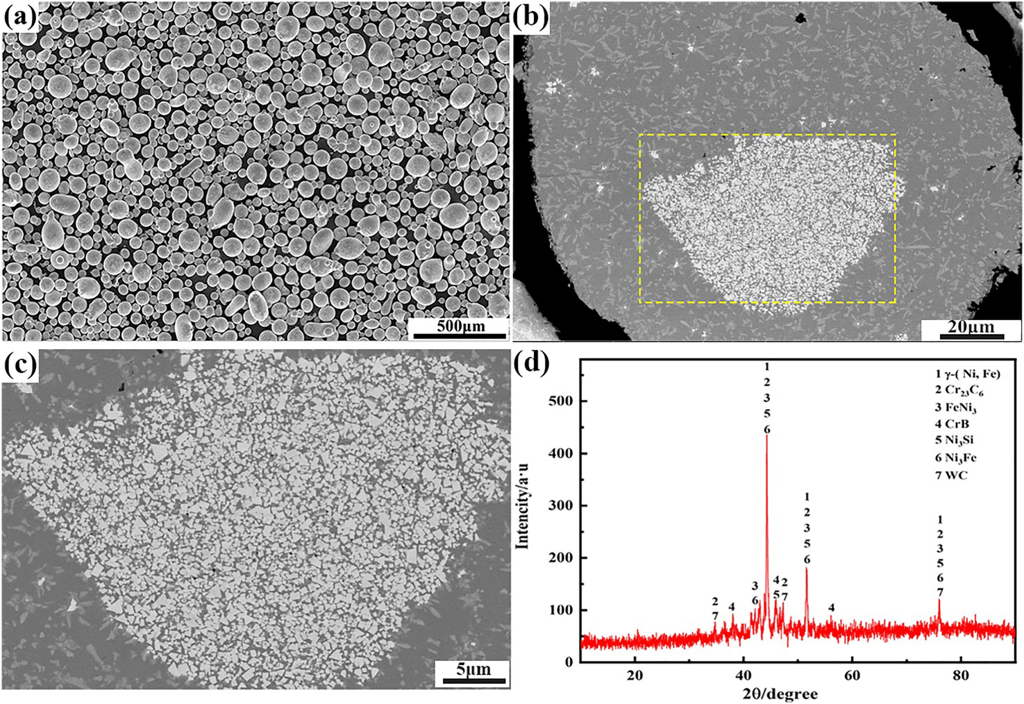
Coating preparation
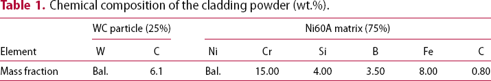
A plasma cladding equipment (PTA-400A) was used to prepare the composite coating on the surface of the copper pipe. Figure 2(a) shows the schematic diagram of the plasma cladding device. Figure 2(b) displays the principle and heat balance model of plasma cladding on the copper pipe. The cladding equipment and principle have been described in detail in Supplementary Materials. According to the previous research of the research group, the copper pipe was preheated to 650°C. The optimised process parameters are shown in Table S1 (Supplementary Materials). Figure 2(c) shows that the appearance of the coating is smooth and uniform. Meanwhile, the coating is well bonded to the copper pipe substrate without crack and pore defects, as shown in Figure 2(d).
(a) Schematic diagram of the plasma cladding device; (b) principle of plasma cladding on copper pipe; (c) surface morphology and (d) cross-sectional morphology of the WC/Ni60A composite coating.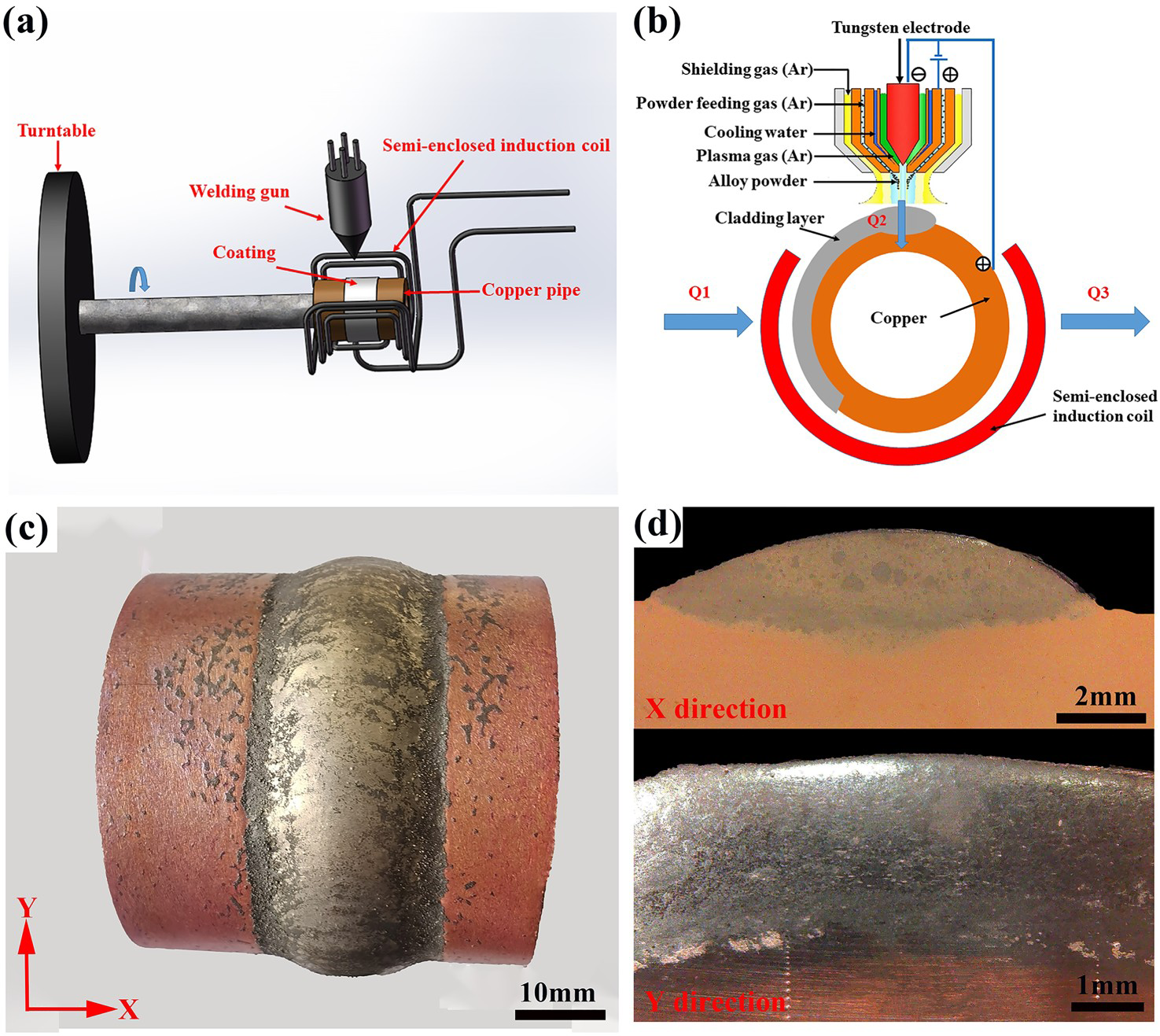
Characterisation and testing
The microstructure and chemical composition of the coating was analysed by the field emission scanning electron microscope (SEM, FEI Nova Nano SEM 450) equipped with an energy dispersive spectrometer (EDS). The phase composition was identified by X-ray diffraction (XRD, Bruker AXS D8 Advance) with a scanning angle ranging from 10° to 90° and a scanning speed of 4° min−1.
An automatic turret digital display micro-hardness tester (HVS-1000M) was used for hardness testing of the coating with a load of 100 g and a holding time of 10 s. The wear behaviour of copper substrate and WC/Ni60A composite coating was evaluated by pin-on-disc friction and wear tester (MMUD-5B). The principle of the wear test' is shown in Figure S2 (Supplementary Materials). The wear tests were carried out at a series of temperatures (RT, 300°C, 400°C, 500°C and 600°C), a normal load of 50 N, a rotating speed of 100 r min−1 and a test time of 60 min.
Results and discussion
Microstructure analysis
Figure 3(d) shows the SEM of the WC/Ni60A composite coating. Figure 3(h) shows the EDS line scan result at the interface corresponds to Figure 3(d). It can be seen that Cu elements significantly decrease from the substrate to the coating, while Si, Ni, Cr and W elements significantly increase, indicating that element diffusion has occurred at the interface. Meanwhile, the dilution rate of the coating was calculated (about 10%). Therefore, a good metallurgical bonding is formed between the WC/Ni60A coating and the copper substrate.
(a) Upper region, (b) middle region, (c) bottom region and (d) interface region of the WC/Ni60A composite coating; (e) magnified image of the marked area in Figure 3(d); (f) magnified image of the marked area in Figure 3(e); (g) XRD pattern of the coating; (h) line scan result corresponding to Figure 3(d).
EDS point analysis results of the points marked in Figure 3.
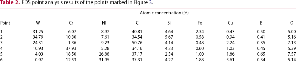
Moreover, a larger-size white WC particle can be observed in Figure 3(d), is due to WC having a high melting point and is not melted [16]. Nevertheless, the combination of the WC particles and the Ni matrix is good, as shown in Figure 3(f). The EDS analysis results of the marked points 3–6 in Figure 3(f) are shown in Table 2. The white core area (point 3) mainly contains C and W elements, and the surrounding light grey (points 4–5) and dark grey (point 6) areas mainly contain C, Cr, W, Ni and Si. According to the results, it can be inferred that after the micro-melting of the edge part of the white WC particles, the excessive C element can form W-rich composite carbides such as Cr–W–C, Ni–W–C, Fe–W–C [17,18] around the WC particles with Ni, Cr, and Fe elements in the alloy as a bridge connecting WC and Ni-based alloy.
From the XRD patterns in Figure 3(g), it can be seen that the composite coating is mainly composed of γ-(Cu, Ni, Fe), Cr23C6, CrB, FeNi3, Ni3Si, Ni3Fe, WC and W2C. Among them, FeNi3, Ni3Si and Ni3Fe are the main phases of eutectic structure, while the WC particles can dissolve to form W2C. Meanwhile, the decomposition products of WC can mutually diffuse and react with the elements in the Ni-based alloy to enhance the interfacial connection between WC and the Ni matrix.
Micro-hardness distribution
Figure 4(a) shows the micro-hardness curves of the WC/Ni60A composite coating. Compared with the copper substrate, the average hardness of the coating is increased by about 17 times. Figure 4(b) shows the point with higher hardness is located on WC or W2C (above 1000 HV0.1), while the hardness value hit on the nickel-based substrate is about 700–800 HV. So the dispersed distribution of the hard phase in the Ni-based alloy acts as a skeleton, which can significantly increase the hardness of the coating. In addition, due to the dilution of the copper substrate, the hardness of the interfacial bonding area of the coating shows a downward trend, which corresponds to the distribution of Cu element.
(a) Curve of micro-hardness distribution curve along the depth of the WC/Ni60A composite coating and (b) SEM image of hardness indentation corresponding to area in Figure 4(a).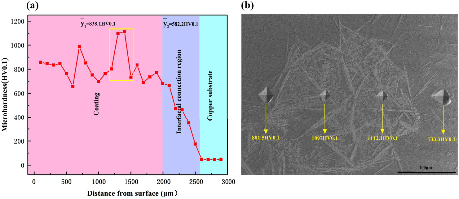
Wear behaviour
Figure 5 shows the friction coefficient and the mass loss of the worn sample at different temperatures. As shown in Figure 5(a), the copper sample always shows the highest friction coefficient (RT and 300°C). Generally, a larger friction coefficient indicates poor wear resistance. The addition of the coating greatly improves the wear resistance of the copper surface. The low friction coefficient of the coating is due to the presence of a large number of reinforcing phases and WC particles. Moreover, the friction coefficient of the coating at 300–500°C is similar. From Figure 5(b), At room temperature, the mass loss of WC/Ni60A coating is 5.5 times lower than that of copper. At 300°C, the average mass loss of copper is up to 85.1 mg. As the temperature increased, the mass loss of the coating first decreased and then increased, and the wear amount was the lowest at about 400°C. However, there is a sudden change in the mass loss of the coating at 500–600°C.
Wear test results of copper and WC/Ni60A composite coating: (a) friction coefficient and (b) mass loss.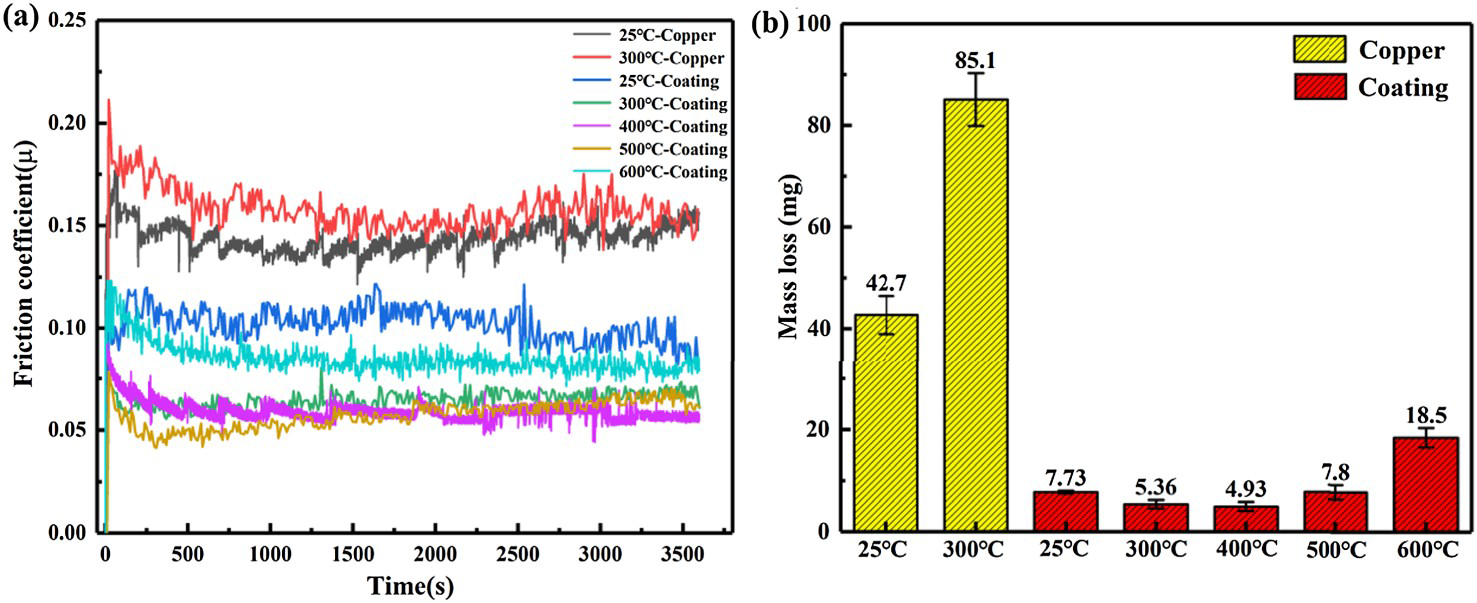
Figure 6 shows the worn morphologies of each sample. A large number of layered spalling areas and spalling pits can also be observed on the copper surface at RT (Figure 6(a)). In addition, some furrows can also be observed at 300°C (Figure 6(b)). Figure 6(c–g) shows the worn morphologies of the WC/Ni60A coating at different temperatures. The worn surface of the coating at RT mainly contains some shallow grooves and spalling pits, which is typical abrasive wear. As the temperature increases, from 300°C to 500°C, the worn morphologies of the coating have no obvious change. However, at 600°C, serious furrows and spalling pits appear on the surface of the coating, accompanied by some brittle fractures. In addition, the surface of the coating at this time contains a large amount of O elements, indicating that it has been seriously oxidised (Table S2 in Supplementary Materials). Therefore, the wear mechanism of the coating at 600°C is abrasive wear, fatigue wear (brittle fracture) and oxidative wear.
Worn morphologies of copper and WC/Ni60A composite coating at different temperatures.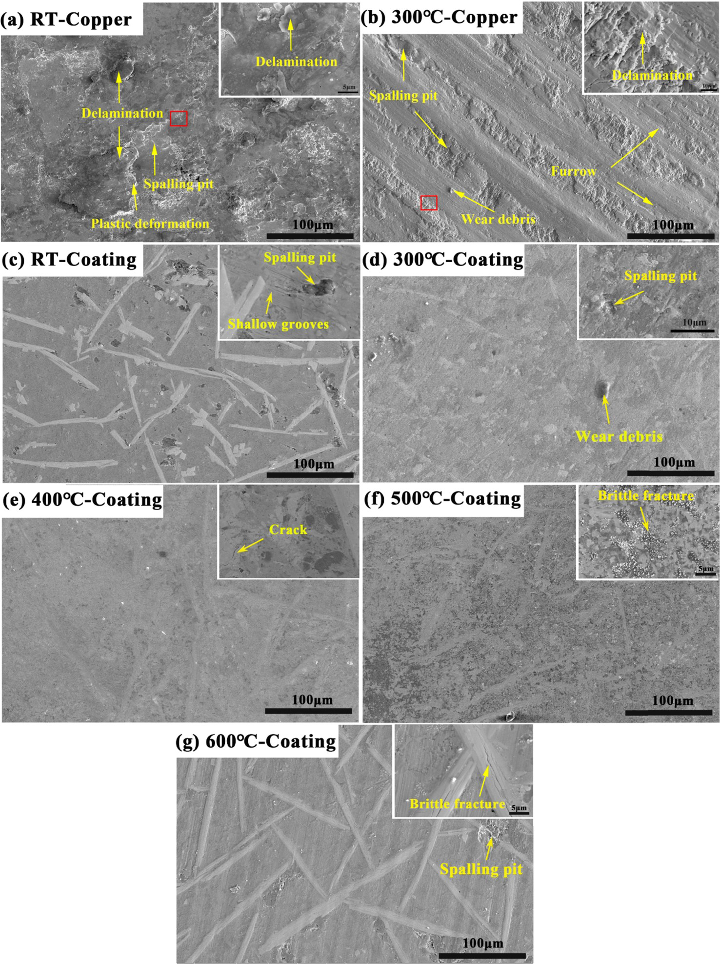
To further clarify the wear process, a cross-sectional analysis of the worn sample was performed, as shown in Figure 7. As shown in Figure 7(a–b), the copper surface was obviously oxidised during the wear process. Meanwhile, delamination occurred under the action of shear stress (adhesive wear). As the temperature increases, the extent of the damaged zone expands, and oxygen elements continue to erode the interior. Therefore, the wear process of copper is oxidation-erosion-stripping. As shown in Figure 7(c), no obvious damage occurs on the coating surface at RT. The long strips of WC inside the coating produce cracks and brittle fractures under the shearing stress. But the long strip or branch WC acts as skeleton support, which makes the wear loss of coating much lower than copper at RT. From Figure 7(d–e), it can be seen that the coating surface is relatively flat at 300–400°C. At 500°C, the coating surface becomes rough. The damage to the coating is mainly manifested as the peeling of the Ni matrix (area 1 in Figure 7(f)) and the peeling of the WC ceramic phases (area 2 in Figure 7(f)). At 600°C, the spalling pit is deeper and the brittle fracture is more serious (Figure 7(g)), resulting in a large amount of wear.
Cross-sectional morphologies of copper and WC/Ni60A composite coating after worn at different temperatures.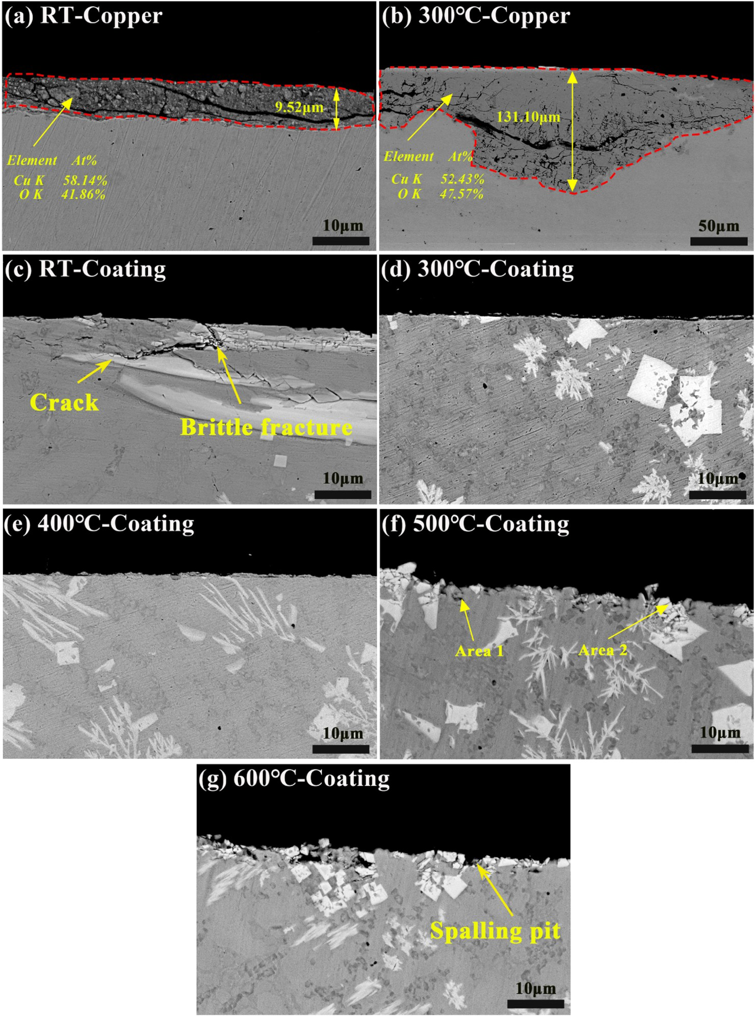
In summary, it can be concluded that the wear behaviour and mechanism of the Ni60/WC coating changed with the increase of temperature. Figure 8 shows the schematic diagram of the coating wear. Combined with EDS mapping results in Table S2 and Figure S4 (Supplementary Materials), it can be seen that the oxidation content of the coating surface increases with the increase in temperature. As shown in Figure 8(a), a dense oxide film was generated on the coating surface. According to literature, the oxides generated on the surface of the coating are excellent high-temperature lubricants [19,20], and the dense oxide film on the surface can prevent further internal oxidation and reduce the abrasive wear behaviour. At 400°C, the wear amount is the lowest, which is due to the increasing oxidation skin, and the wear mechanism is oxidative wear. However, with the increase in temperature, the surface was softened gradually although it also was severely oxidised. Part of the oxide film was damaged and peeled off from the worn surface under the action of shear stress. As shown in Figure 8(b), the oxidised surface was destroyed at a high temperature and was stripped together with the Ni substrate. Meanwhile, the wear became more intense and the amount of wear was increased greatly with the increase in temperature. At 600°C, the wear mechanism changed significantly, which is shown as abrasive wear, fatigue wear (brittle fracture) and oxidative wear. Therefore, in practical applications, it is necessary to control the working temperature of the coating below 600°C as much as possible.
Cross-section morphology and schematic diagram of the coating wear: (a) at 400°C and (b) at 600°C.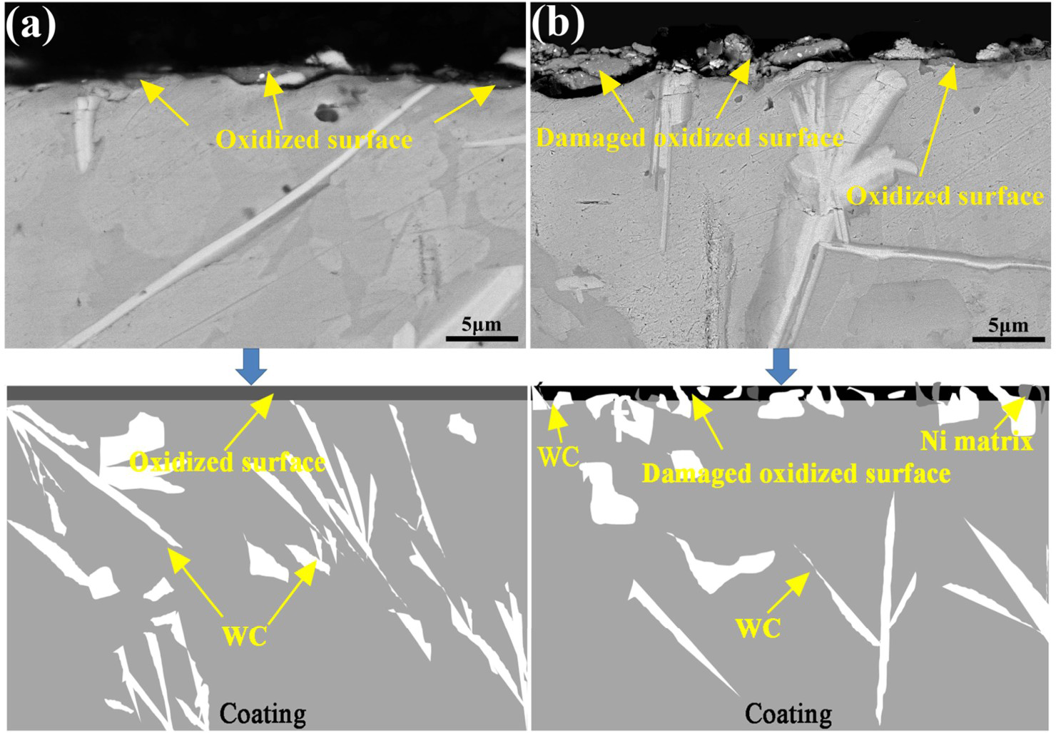
Conclusions
In this work, 25%WC/Ni60A composite coating was successfully prepared on copper using plasma cladding. The main conclusions are as follows:
A good metallurgical bond forms between the coating and the copper substrate, due to the occurrence of element diffusion. The coating mainly contains γ-(Cu, Ni, Fe), Cr23C6, CrB, FeNi3, Ni3Si, Ni3Fe, WC and W2C phases. Among them, FeNi3, Ni3Si and Ni3Fe are the main phases of eutectic structure, while the WC particles can dissolve to form W2C. Due to the fine-grain strengthening of the Ni matrix and the dispersion strengthening of the hard phases such as WC and W2C, the hardness of the coating is increased by 17 times compared with the copper substrate. With the rise in temperature, the wear resistance of the coating first increased and then decreased. At 400°C, the coating had the best wear resistance due to the lubricating effect of the oxide layer. At 600°C, the wear resistance was significantly reduced, mainly because the wear mechanism changed to abrasive wear, fatigue wear (brittle fracture) and oxidative wear. For practical applications, the operating temperature of the composite coating should be kept below 600°C as much as possible.
Footnotes
Disclosure statement
No potential conflict of interest was reported by the author(s).