
Abstract
The diversified microstructure and complex composition of cast iron affect its friction and wear properties. In this work, three kinds of cylinder liner cast iron with different graphite morphologies were selected to analyse the friction and wear properties. Microstructure effects on tribological properties during friction were investigated by finite element simulation and pin-on-disc dry friction test. Wear mechanisms were studied using scanning electron microscopy and X-ray photoelectron spectroscopy. The results show that graphite bears a considerable strain value during the friction process, which is prone to wear and fall off, and the fallen graphite can reduce the friction coefficient. Ferrite around graphite can buffer stress, but it also can reduce wear resistance. And the more significant the lamellar spacing of pearlite, the more abrasive and adhesive effect.
Introduction
The cylinder liner and piston ring are a vital pair of friction couple in the internal combustion engine. According to statistics, more than 20% of engine friction loss occurs on cylinder liners and piston rings [1,2]. Usually, the cylinder liner and piston ring operate under lubrication. However, when the piston ring is at the top dead centre (TDC), it is difficult to form a complete oil film due to high explosion pressure and low linear speed, so it is easy to have boundary lubrication or dry friction, leading to severe wear problems (such as cylinder liner scuffing) [3,4]. Therefore, the wear resistance of cylinder liner material is a critical factor affecting the reliability and service life of the internal combustion engine [5,6]. From the microscopic scales, the wear process of cast iron is the shedding process of microstructure. Therefore, it is essential to study the influence of cylinder liner cast iron microstructure on the wear process. At the same time, it also can provide data support for optimising cast iron microstructure and developing new wear-resistant materials.
Owing to the diversity and complexity of cast iron microstructures, it is challenging to study the influence of different microstructures on the wear properties and establish the mapping relationship. The microstructure of cast iron mainly includes graphite, pearlite, ferrite, and the hardening phase. Many studies have been conducted on the influence of these specific microstructures on friction performance [7-10]. Graphite is a constituent phase in cast iron, significantly affecting the wear resistance [10]. Graphite can form a lubrication film to limit the direct contact between friction surfaces and decrease wear rate [11-13]. Moreover, the graphite shedding position will store thicker oil film to achieve the effect of reducing wear in a starved lubrication state [14]. In addition, the existence of graphite can also improve the thermal conductivity of cast iron [15-17]. References [10,17-19] elaborated on the influence of graphite on wear performance from aspects of stress concentration, thermal conductivity, crack propagation, and thermal fatigue. Another significant microstructure of cast iron is pearlite, which constitutes the matrix of cast iron material. Its lamellar structure can effectively improve the fatigue wear resistance of cast iron. The wear performance of pearlite is mainly affected by lamellar spacing [20,21]. Some research has shown that pearlite with small lamellar spacing has an excellent combination of strength and toughness and good wear resistance [9,22]. Another reason for the excellent wear resistance of pearlite is that it can produce large plastic deformation during the friction process and even form a thin nanocrystalline layer on the friction surface after deformation. The formation of the deformed layer can significantly improve its wear resistance [23-26]. The hardening phase (such as carbide and phosphorus eutectic [7,27]) is the main strengthening phase of carbon steel. It can protect the matrix structure from further cutting due to high hardness. Zheng et al. [28,29] studied the two-body and three-body abrasive wear behaviour of cementite and proposed the physical model of the wear process between cementite and matrix structure. Sasaki et al. [30] studied the effect of cementite content on wear resistance, and the results showed that steel's strength and wear resistance increased with the cementite volume fraction. Coronado et al. [31,32] studied the influence of load on the wear performance of cementite. The results showed that when the load was small, cementite as a hardening phase could increase the wear resistance of cast iron. Cementite was prone to brittle fracture when the load increased, forming abrasive particles and accelerating wear.
Although researchers have done much research on the effect of microstructure on the wear properties of cast iron, most of these studies aim at a specific microstructure. However, there are few reports on the synergistic effect of various microstructures. In this work, the finite element simulation (FEM) and Pin-on-Disc (PoD) dry friction test were used to study the influence of different microstructures on wear performance. The wear process and mechanism of each microstructure during friction were explained, which can provide data and theoretical reference for the microstructure optimisation and development of new wear-resistant cast iron.
Material and methods
Metallographic experiment
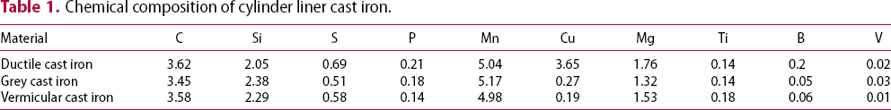
Chemical composition of cylinder liner cast iron.
Friction and wear experiments
Wear tests were carried out on a pin/ball-on-disc wear testing machine (Rtec MFT-5000) as per the ASTM G 99-17 [33]. The samples were grounded and polished before the experiment to ensure the surface roughness Ra ≦ 0.2. A ball of GCr15 with a hardness of 62 HRC and a diameter of 6.35 mm was in contact with polished samples. The experimental parameters are presented in Table 2. The sampling position and experimental principle are shown in Figure 1. The samples were cleaned ultrasonically in anhydrous ethanol three times for 5 min each time, and each material was repeated three times to ensure the accuracy of the results. The high precision electronic balance (Precision 0.01 mg) was used for wear loss measurement. The microstructure and morphology of worn surfaces were observed using optical microscopy (OM) and scanning electron microscopy (SEM). The composition of oxide films on the worn surface was analysed by X-ray photoelectron spectroscopy (XPS).
Sample size and experimental principle. Test parameters.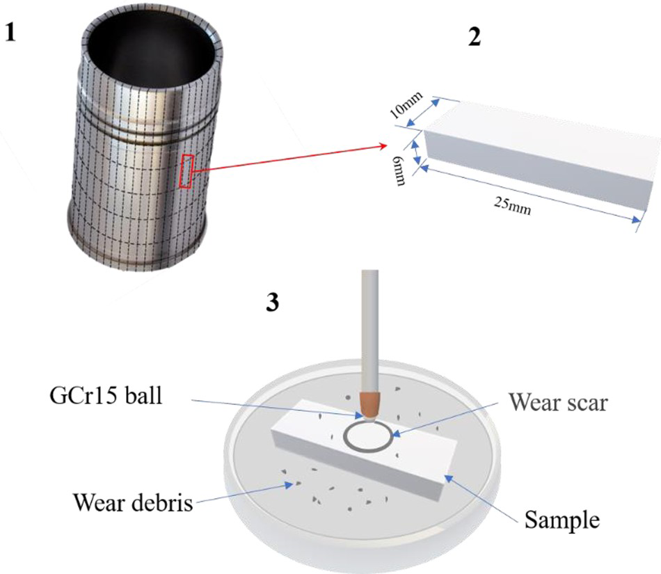
Establishment of finite element model
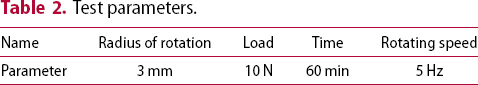
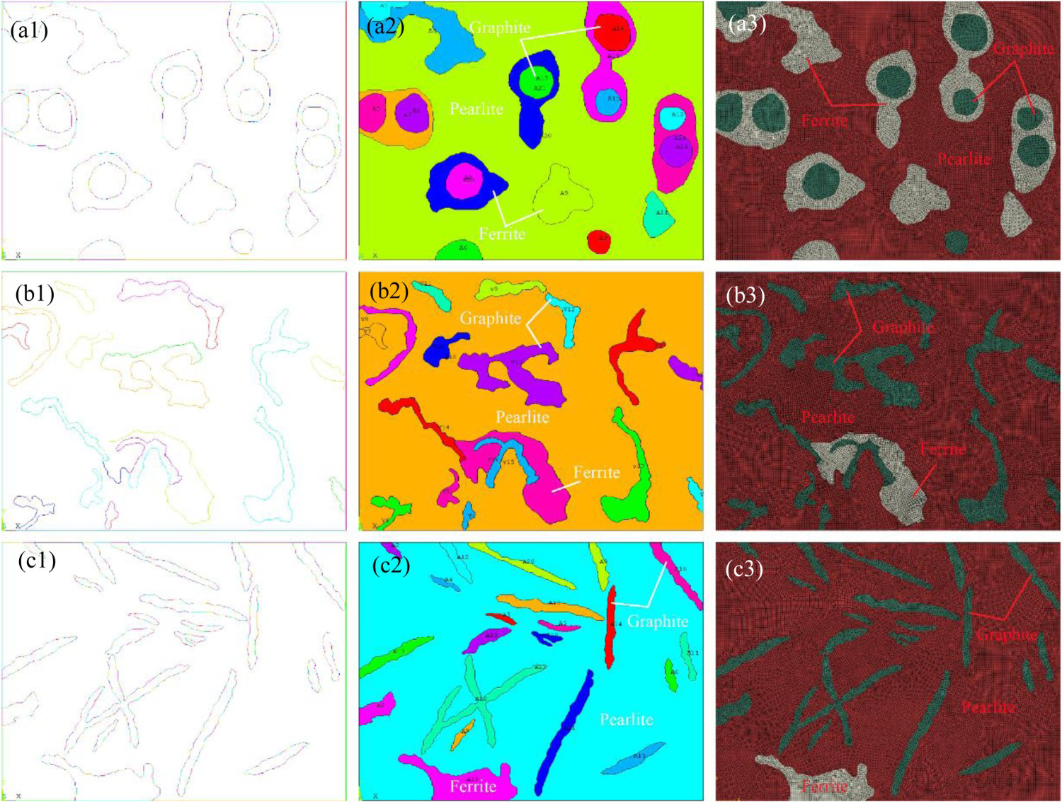
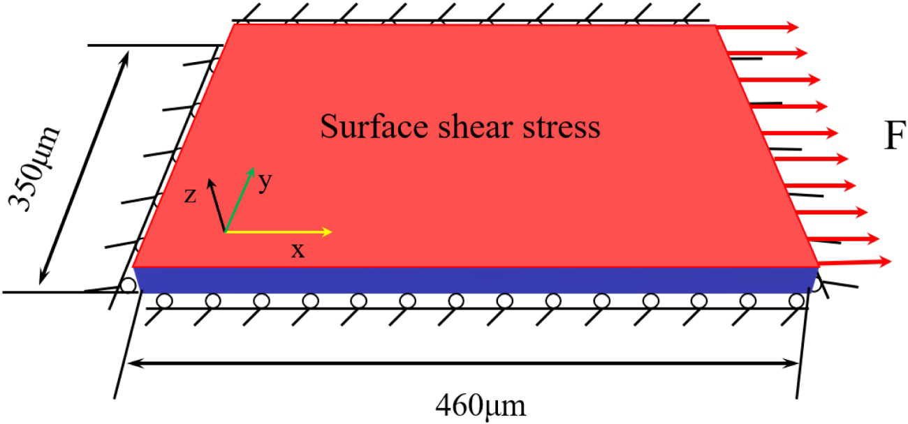
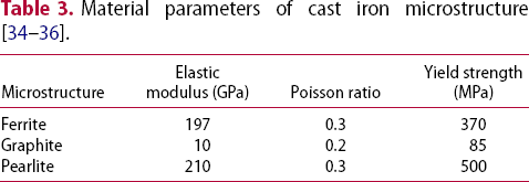
To accurately simulate the morphology characteristics, the finite element models were established according to the actual microstructure distribution. The steps of establishing the model are as follows: microstructures were identified and then dyed with different colours. The dyed photographs were recognised, and the data points of different organisational boundaries were extracted (as shown in Figure 2). Then, the microstructures’ profiles were modelled in commercial software ANSYS. Finally, the models meshed in pre-processing software. The mesh type is mainly hexahedral, and a small number of tetrahedral elements are in the transition positions of different microstructures. The element number of the three models is 152792, 132076, and 143472 for DCI, GCI, and VCI, respectively. Then the meshed models were imported into the commercial software ABAQUS to set the material properties (as shown in Figure 3). Table 3 shows the material parameters of cast iron microstructure. In order to simulate the friction force of the specimen in the friction process, the boundary conditions were applied to make the model surface subject to pure shear stress, i.e. the bottom boundary is fixed, and the top boundary can move freely under the action of friction. A controlled surface shear stress is applied on the top boundary. The schematic diagram of the finite element model with boundary conditions and size is shown in Figure 4.
Extraction of microstructure contour of cast iron: (a) DCI; (b) VCI; (c) GCI. Establishment of cast iron models and meshing:(a) DCI; (b) VCI; (c) GCI. Schematic drawing of the boundary conditions applied to finite element model.
Results and discussion
Microstructure analysis
The graphite shape was evaluated by Formula1 [37]. The form of grey cast iron (GCI) graphite is lamellar and randomly oriented A-type. In addition to vermicular graphite, vermicular cast iron (VCI) also contains a small amount of spherical graphite (as shown in Figure 5).
Graphite morphology of cast iron materials: (a) GCI; (b) DCI; (c) VCI.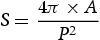
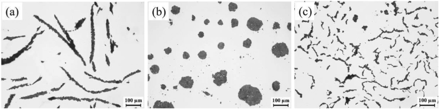
Figure 6 shows the microstructure distribution of the cast iron. The microstructures of three cast irons are mainly pearlite, graphite, and a small amount of ferrite, and the graphite of DCI is surrounded by ferrite. The content of different microstructures was calculated by the area ratio method. Table 4 shows the content of each microstructure in cast iron.
Microstructure of cast iron materials: (a) GCI; (b) DCI; (c) VCI. Contents of each component in the matrix.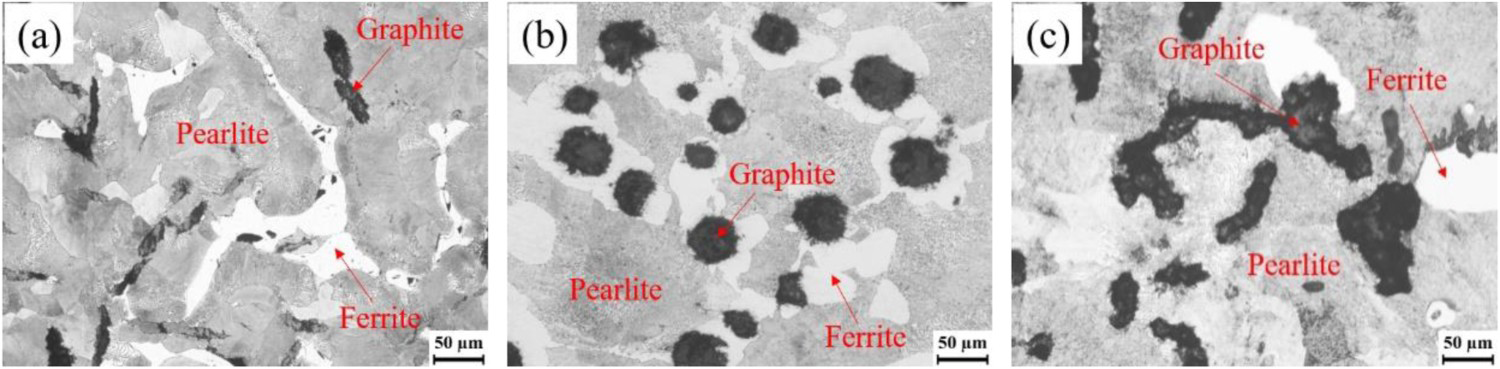
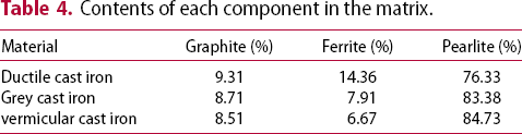
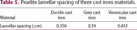
According to the analysis, it can be seen that the primary matrix microstructure of three cast irons is pearlite, which significantly influences wear resistance. The pearlite (as shown in Figure 7) morphology of three cast irons is mainly lamellar, and the DCI contains a small amount of granular pearlite. The lamellar spacing of VCI and GCI is relatively large, while that of DCI is the smallest. Table 5 shows the lamellar spacing of three kinds of pearlite.
Pearlite morphology of cast iron materials: (a) GCI; (b) DCI; (c) VCI. Pearlite lamellar spacing of three cast irons materials.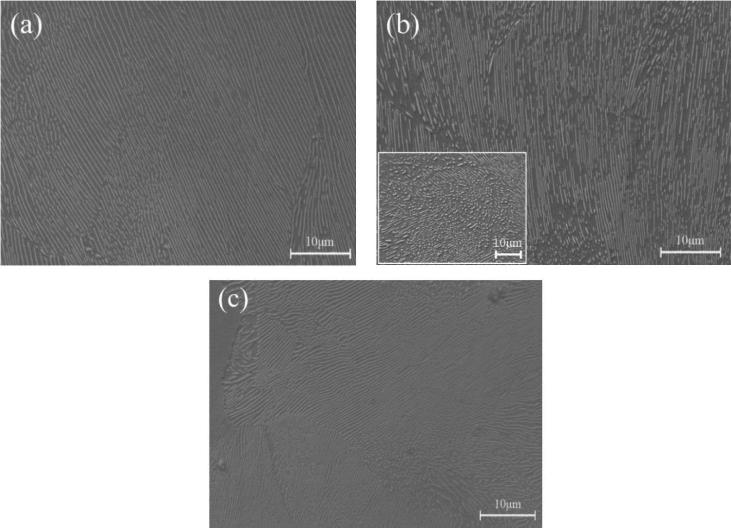
Stress–strain analysis of microstructure
Microstructure effects on friction and wear properties can be understood more clearly by analysing its force in the friction process. Figure 8 shows the stress distribution of different microstructures under shear force. From the stress distribution nephogram (as shown in Figure 8(1)), it can be seen that the stress of graphite is the smallest, and that of pearlite is the largest, which indicates that the pearlite mainly bears the friction force during the friction process. In contrast, graphite can hardly bear the force. Moreover, the stress value of matrix structure around graphite is the largest, which agrees with the literature [38]. It shows that during the friction process, stress concentration will occur around the graphite, and this phenomenon is mainly due to the significant difference in the mechanical properties between the graphite and the matrix structure. At the same time, it can be seen from the stress variation curve on the path line marked in the nephogram (Figure 8(2)) that the maximum stress around graphite of VCI and GCI is similar. While the stress around spherical graphite is minor, this is mainly due to the matrix structure around spheroidal graphite being ferrite. While for VCI and GCI, the matrix structure around graphite is the higher strength pearlite, and it can bear more considerable stress than ferrite. It also shows that the ferrite around the graphite can buffer the stress concentration for DCI, which can be seen from the local amplification position of the stress value change curve. At the contact position between ferrite and pearlite, the stress of pearlite is greater than that of ferrite; however, this stress concentration is negligible due to the slight difference in mechanical properties between ferrite and pearlite.
Stress distribution nephogram of microstructure and stress value on corresponding path line: (a) DCI; (b) VCI; (c) GCI.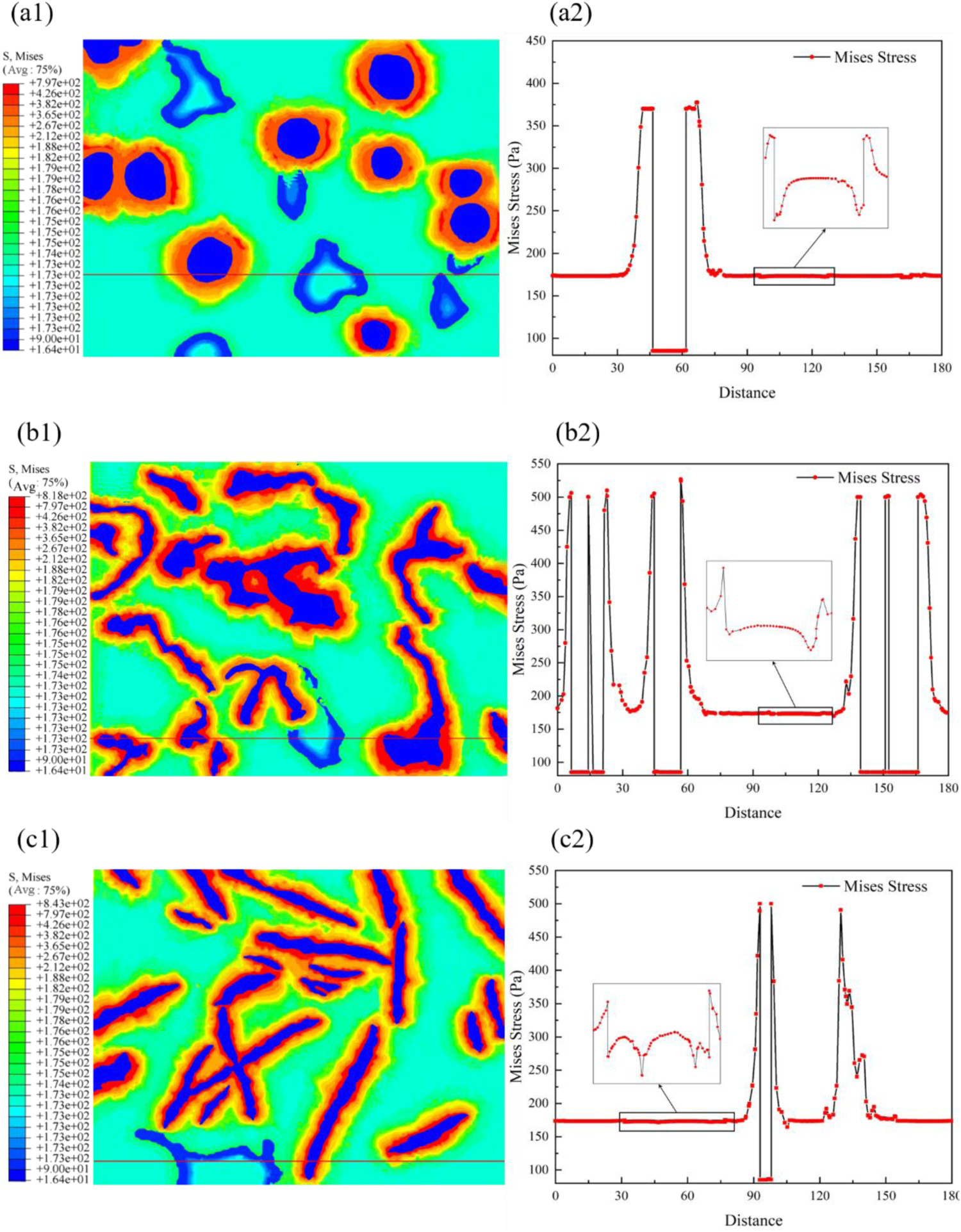
Figure 9 is the equivalent plastic strain distribution of three materials under shear stress. It can be seen that the equivalent strain of graphite is the largest, and that of pearlite is the smallest, which indicates that when the surface is subjected to tangential friction, the graphite will first wear off. Many studies have proved that the graphite will first fall off and form defects during friction [39-41]. Even some researchers have pointed out that graphite can be regarded as a hole to study the micromechanical damage of cast iron material [42]. From the maximum equivalent strain values of the three materials, we know that graphite's morphology and size seriously affect its performance. The equivalent strain of graphite in DCI is the largest, and that in GCI is the smallest. It is mainly due to the considerable relative length of spherical graphite in the friction direction and thus bears a significant strain value. The graphite morphology of GCI is mainly lamellar, so when the graphite is perpendicular to the friction direction, the relative width of graphite in this direction is small, and the strain is slight. In addition, it can be seen that the deformation of the matrix structure around graphite is more significant than that away from it. For DCI, the matrix structure around the graphite is ferrite, which has a more considerable strain than pearlite. It can also reflect that when the graphite is worn off, the matrix structure around the graphite is more accessible to wear than away from it, and ferrite is more accessible to wear off than pearlite.
Equivalent plastic strain distribution nephogram of microstructure: (a) DCI; (b) VCI; (c) GCI.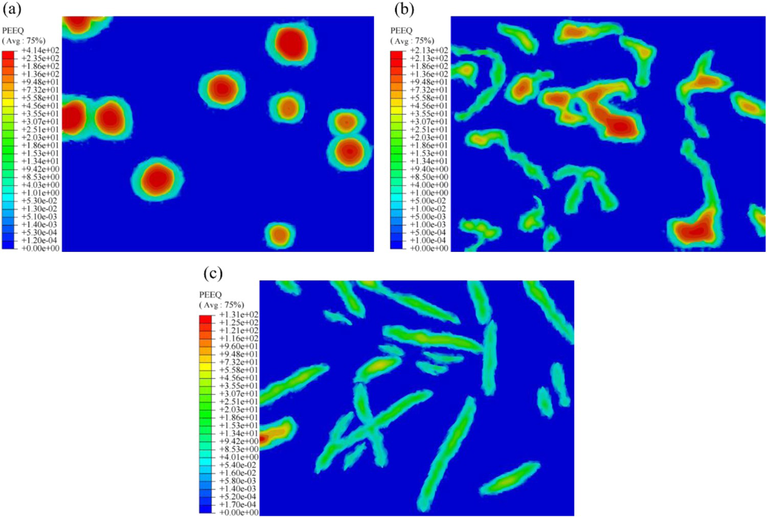
Analysis of wear performance
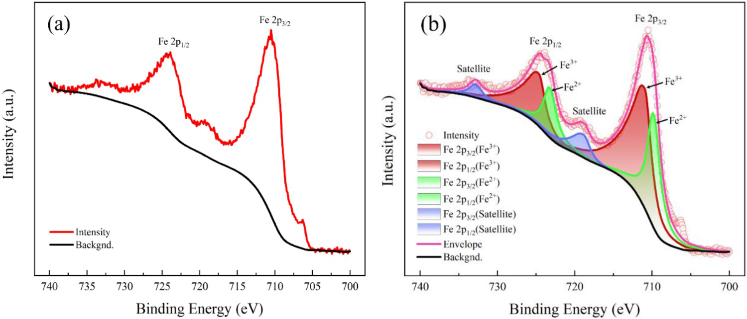
Figure 10 shows the friction coefficient of three kinds of cast irons. It can be seen from Figure 10(a) that the friction coefficient of three materials decreases first and then increases gradually, which is in accord with the literature [43]. Owing to the low surface roughness of the sample after grinding and polishing, the friction process was stable, and the friction coefficient was small at the beginning of the experiment. With the progress of friction, the surface was gradually worn, and the wear scar of the sample became rough, so the friction coefficient increased gradually. For VCI and DCI, the friction coefficient reaches the maximum and decreases gradually, possibly due to the self-lubricating effect on the wear scar [23]. The research has shown that when dry friction experiments on martensite and pearlite steel with a layered structure, the pearlite will undergo plastic deformation, oxidation, and amorphous behaviour during the friction process. And then, a layer of nano-oxide particles can eventually be formed on the friction surface to reduce friction. Figure 11 shows the wear scar morphology and elemental analysis. A layered structure was formed on the surface and had a high oxygen content. In order to determine the composition of surface oxide films, the worn surfaces were tested by X-ray photoelectron spectroscopy (XPS). Figure 12 is the XPS spectrum of Fe 2p on the worn surface. The peak fitting of the Fe 2p chemical state spectrum refers to the literature [44]. The results show that the valence states of iron on the worn surface are mainly Fe3+ and Fe2+. Because FeO is extremely unstable and easily oxidised, there are apparent satellite peaks in the peak fitting of the chemical state spectrum of Fe 2p, which means that the oxide film is a mixture of Fe3O4 and Fe2O3. The result is consistent with that in the literature [23]. The formation of oxide is related to the contact flash temperature during friction. According to previous research results, when Fe3O4 is formed on the surface, the contact temperature is above 200°C [45]. The friction heat varies for different cast iron materials due to their microstructure. GCI produces less heat during friction than the other two kinds of cast iron, mainly related to its higher thermal conductivity [17,46]. So, the friction coefficient of GCI did not show a significant decline, which may be associated with the low friction temperature, and it is not easy to form a complete oxide film.
The friction coefficient of three materials: (a) friction coefficient; (b) average friction coefficient. Wear scar morphology and local position C and O EDS mapping (figure b): (a) wear scar morphology; (b) structure of a dense layer of wear scar. The XPS spectrum of Fe 2p for the worn surface: (a) the high-resolution spectrum of Fe 2p and (b) peak-fitting of Fe 2p chemical state spectrum.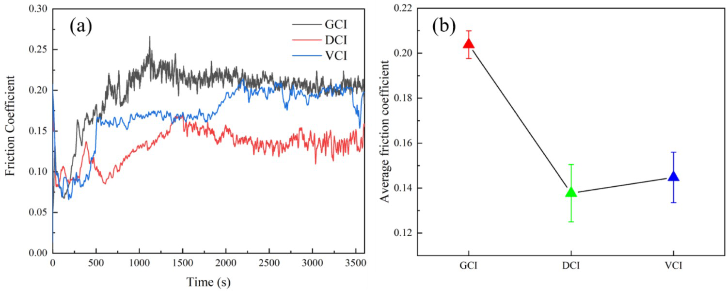
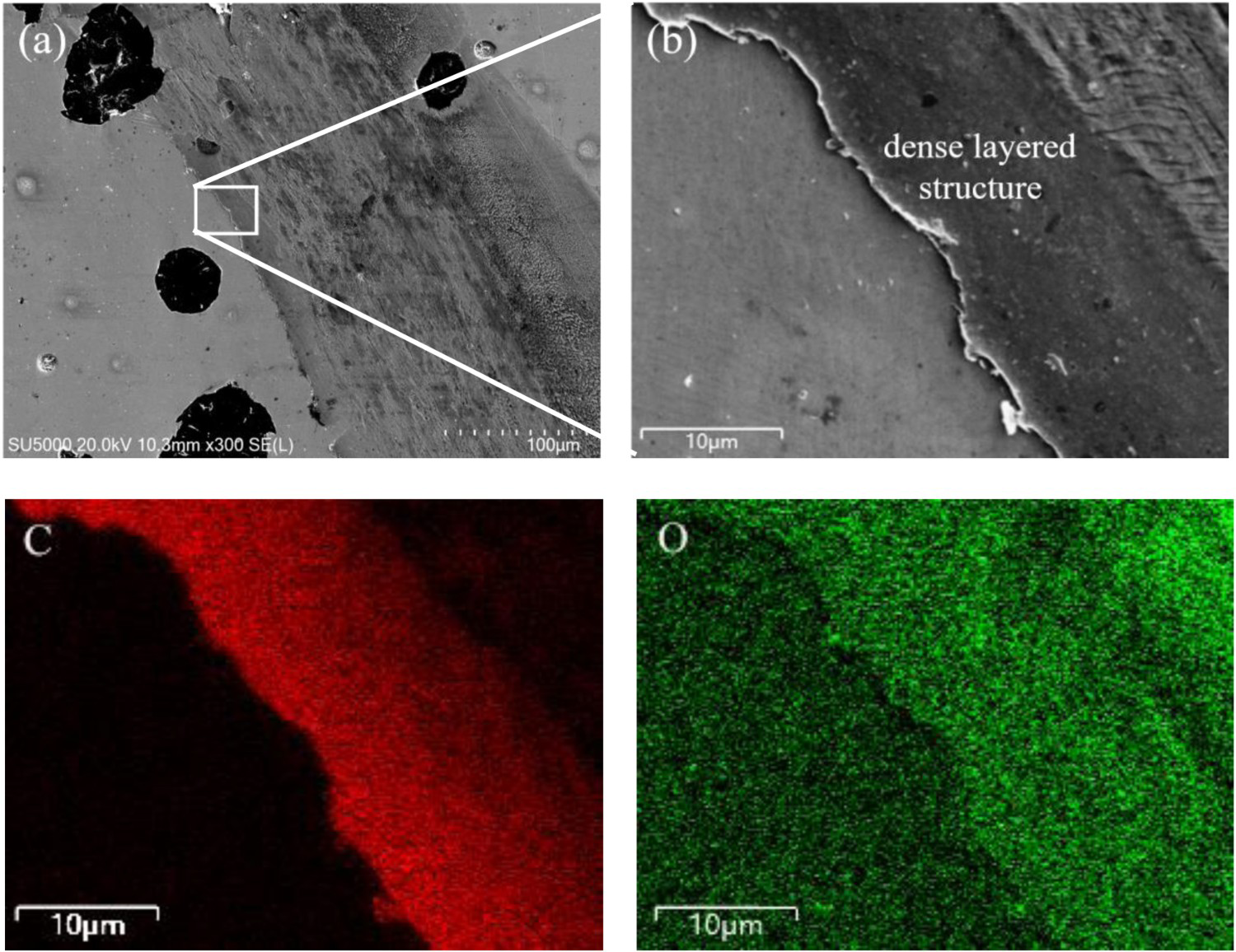
It can be seen from the average friction coefficient (Figure 10(b)) that the friction coefficient of DCI and VCI is lower, while that of GCI is higher. Many studies have shown that graphite morphology and size seriously affect the friction coefficient of cast iron [43,47]. This paper mainly analyses the influence of graphite change on friction coefficient during friction. It can be seen from the analysis in Section ‘Stress–strain analysis of microstructure’ that graphite was easy to wear and fall off under the friction force and then formed graphite particles to enter the wear scar surface. Moreover, graphite is an essential solid lubricant [48], so the graphite entering the wear scar position can reduce the friction coefficient [39-41]. The element distribution at the wear scar (Figure 11) shows carbon enrichment. According to the analysis of the equivalent plastic strain of the three materials in Section ‘Stress–strain analysis of microstructure’, Spherical graphite is easier to wear and fall off than flake graphite. In addition, the graphite will be closed due to the matrix structure's plastic deformation during the GCI's wear process [49], which will be discussed in Section ‘Microstructures change during wear of cast iron’. As a result, due to the lubrication effect of graphite, DCI has a low friction coefficient, while that GCI is high. It is different from the results reported in the literature [43,47], the reason may be that the microstructure distribution of the material is different, and the effect of ferrite on friction and wear properties is ignored.
Figure 13 shows the wear loss of three materials. As can be seen from Figure 13(a), the wear loss of DCI is the largest, about 2.5 times that of VCI, and the wear loss of GCI is about 1.3 times that of VCI. This result is consistent with those reported in the literature [17,47]. According to the analysis of Section ‘Establishment of finite element model’, the graphite of DCI is more accessible to wear off than the other two kinds of cast iron due to its large size and the surrounding matrix structure being ferrite. In addition, the existence of graphite will lead to stress concentration in the surrounding matrix structure. Compared with the pearlite matrix of GCI and VCI, the microstructure around the graphite of DCI is mainly ferrite. On the one hand, ferrite is more prone to wear than pearlite due to its flexibility and ductility. As discussed in the literature [10,50-52], increased ferrite content in cast iron material can reduce its wear resistance. On the other hand, due to stress concentration, ferrite around graphite is more prone to wear and fall off than that in the pearlite matrix. The analysis of the microstructure content of the three materials in Section ‘Microstructure analysis’ shows that the graphite and ferrite content of DCI is higher than that of the other two materials. Hence, the wear loss of DCI is significant. For VCI and GCI, although the equivalent plastic strain value of vermicular graphite is greater than that of lamellar graphite, there is little difference between them. In addition, the study [53] has shown that the graphite of VCI has a sizeable binding force with the matrix structure, and it is not easy to wear off, so the wear loss of the two kinds of cast iron is slight. It can also be seen from the cross-sectional morphology of the wear scar (Figure 13(b)) that the depths of the two cast irons are shallow. The different lamellar spacing of pearlite may cause various wear losses between VCI and GCI, and some research showed that the smaller the lamellar spacing of pearlite is, the better wear resistance is [9]. Therefore, the wear resistance of the matrix structure of VCI is better than that of GCI. Although the lamellar spacing of DCI pearlite is small, its wear loss is mainly affected by graphite and ferrite. In addition, the larger wear loss of GCI may also be related to the difficulty in forming a complete oxide film on its surface. Studies have shown that the oxide film can reduce the friction coefficient and wear rate [54,55].
Wear losses of three materials: (a) wear loss; (b) sectional profile of wear scar.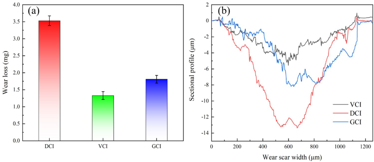
Microstructures change during wear of cast iron
Figure 14 shows the crack propagation on the wear scar surface. The figure shows that the cracks of three kinds of cast iron mainly appear around the graphite, consistent with the analysis results in Section ‘Stress–strain analysis of microstructure’. At the same time, the experimental results also prove the correctness of the simulation process. The crack propagation of DCI is mainly along the edge of spherical graphite, which leads to the graphite falling off quickly. For the damaging micro mechanism of DCI, some researchers also observed by in-situ SEM that the crack source mainly occurred at the edge or centre of graphite [56], which also proved that graphite is the most prone to damage. The stress concentration is relatively slight due to the smooth contact between the spherical graphite edge and the matrix structure. For GCI and VCI, the crack mainly occurs at the tip of graphite and propagates along the wear scar surface. The matrix structure will fail when different crack propagation combines or extends to the adjacent graphite position. Therefore, the shape and average distance between graphite will seriously affect the generation and propagation of cracks. Some studies have shown that the graphite morphology of cast iron changes from lamellar to vermicular to spherical, the stress concentration effect decreases, and the wear resistance increases gradually [18]. In this research, the severe wear of DCI is mainly caused by graphite and its surrounding ferrite.
Cracking location of three cast irons: (a) DCI; (b) VCI; (c) GCI.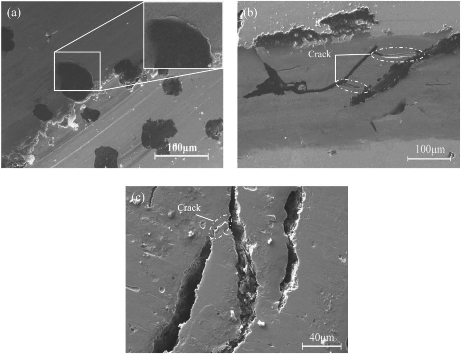
Figure 15 shows the wear scar and debris morphology of three kinds of cast iron. The worn form of DCI is mainly oxidation and abrasive wear. There are furrows and lamellar shedding on the wear scar surface (Figure 15(a1)), and the wear debris also shows an apparent flakes shape (Figure 15(a2)). The wear forms of GCI and VCI are mainly abrasive and adhesive, and the wear debris morphology is mainly fine granular (Figure 15(b2,c2)). The wear form of cast iron is primarily affected by graphite and matrix structure. According to the analysis in Section ‘Stress–strain analysis of microstructure’, when the cast iron was subjected to shear stress, stress concentration occurred around the graphite, resulting in cracks that expanded on the matrix structure around the graphite and finally leading to fatigue spalling and wear debris formation. On the one hand, the debris will undergo complex physical and chemical changes during repeated rolling, resulting in a self-lubricating effect [23]. On the other hand, the abrasive particles will also plow the surface and cause abrasive wear. Due to the increase of roughness caused by surface wear, the adhesion wear will occur under the combined friction force and heat (Figure 15(b,c)). The pearlite lamellar spacing of DCI is small and has good wear resistance [9]. Therefore, the surface adhesion and abrasive wear are light, indicating that the wear loss of DCI is mainly affected by graphite and ferrite. Moreover, the wear debris of DCI is mostly flake, which is not only caused by the shedding of pearlite around graphite but also may be formed by the fatigue shedding of the oxide layer formed by compacted wear debris [57]. For VCI and GCI with large lamellar spacing, the worn surfaces mainly presented tearing from adhesive trace and apparent furrow phenomenon. In addition, graphite with smaller width in GCI was closed due to the plastic deformation of pearlite under friction force (the position marked by the red arrow in Figure 15(b1)), which also led to the incomplete overflow of graphite and reduced its lubrication effect. In the study performed by Ghasemi et al. [49] regarding the relationship between flake graphite orientation, smearing effect, and closing tendency, it was found that the abrasive wear mechanism will intensify the closing process of flake graphite.
Wear scar and wear debris morphology of cast iron materials: (a) DCI (b) VCI (c) GCI.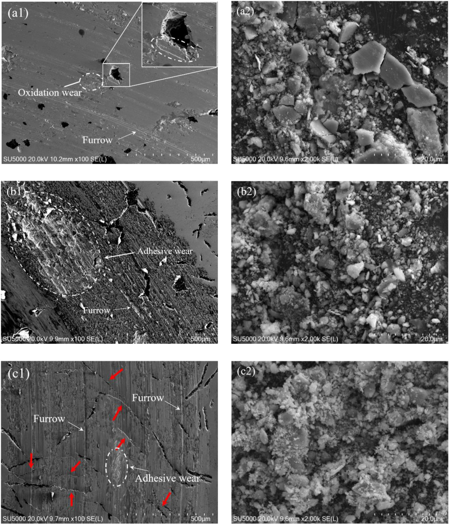
Conclusion
Through the finite element simulation and dry friction experiment of three different cast iron materials, the effects of different microstructures on the friction and wear properties were analysed, and the following conclusions can be reached:
Among the three materials, the friction coefficient of DCI is the smallest, and that of GCI is the largest. Graphite falls off first in the friction process and enters the ink mark surface can play a role in reducing friction. Flake graphite will close when it is perpendicular to the friction direction, weakening the lubrication effect. The wear amount of DCI is 2.5 times that of VCI and 1.9 times that of GCI. The spherical graphite and its surrounding ferrite are seriously worn under the action of friction, and the pearlite is the main factor affecting the wear of GCI and VCI. The primary wear mechanism of DCI is oxidation and abrasive wear, while that of GCI and VCI is mainly adhesive and abrasive wear. The wear mechanism of cast iron is primarily affected by pearlite. The smaller the pearlite lamellar spacing is, the lighter the abrasive and adhesive wear are.
Footnotes
Disclosure statement
No potential conflict of interest was reported by the author(s).