
Abstract
In this study, single wire arc additive manufacturing (SWAAM) and multi wire arc additive manufacturing (MWAAM) were used to fabricate the TC11 alloy. Microstructure and mechanical properties of TC11 alloy were studied. The results showed that the microstructure of MWAAM TC11 alloy composed of α and β phase, and the proportion of β phase increased slightly than that of SWAAM TC11 sample. Compared with the SWAAM TC11 sample, the microhardness of MWAAM TC11 alloy sample increased from 382 to 407 HV, and average ultimate tensile strength of MWAAM TC11 alloy sample increased from 922.01 to 934.56 MPa. The results indicate that the addition of wires can significantly improve both manufacturing efficiency and mechanical properties of TC11 alloy components.
Introduction
Titanium and its alloys are widely used in aerospace, petrochemical, biomedical and other fields because of their light weight and high specific strength [1,2]. Recently, wire arc additive manufacturing (WAAM) technology has received more and more attention due to its ability to manufacture large-scale key metal parts at a lower cost [3,4]. However, large structural parts put forward higher requirements for manufacturing efficiency, and the traditional single wire feeding arc additive manufacturing technology is difficult to meet this requirement.
Multi wire synchronous feeding is an effective method to improve the deposition efficiency of WAAM. In order to ensure the full melting of wire, multi wire arc additive manufacturing (MWAAM) often requires large arc heat input [5]. However, the larger heat input leads to the coarse grains of the formed parts, which leads to the anisotropy of mechanical properties and the reduction of comprehensive mechanical properties. The existing grain refinement methods mainly include interlayer cooling, high-pressure rolling and element alloying. Although these methods can achieve grain refinement, they prolong the manufacturing cycle and further increase the manufacturing cost [6,7]. It is of great significance to the large-scale promotion and application of MWAAM to reduce the heat input while improving the manufacturing efficiency, refining the grain and improving the comprehensive mechanical properties of the structural parts.
Therefore, in order to improve the manufacturing efficiency and mechanical properties of WAAM deposited materials, this study used hot MWAAM technology to change the internal microstructure and mechanical properties of as-received TC11 titanium alloy. The microstructure and comprehensive properties of TC11 titanium alloy components made of single wire and multi wire arc additive manufacturing were studied.
Materials and methods
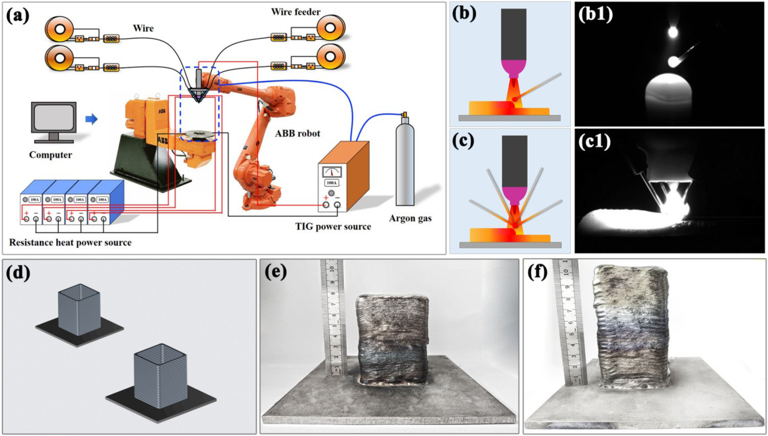
TC11 wire (Ti–6.5Al–3.5Mo–1.5Zr–0.3Si) with 1.2 mm diameter was used as raw materials. The dimension of the TC11 substrate plate was 150 mm×150 mm × 5 mm. The MWAAM system consisted of a 6-axis ABB robot and four wire feeders with hot wire resistances. The manufacturing process was illustrated in Figure 1(a). The energy for all equipment in the WAAM process was individually powered and controlled by computer. The detail about the MWAAM system had been explained in previous work [3]. In this work, the single wire and multi wire modes were selected to fabricate TC11 alloy components, as shown in Figure 1(b, c). Figure 1(b1, c1) shows the wires during the base current period in the manufacturing process. The selected MWAAM process parameter was shown in Table 1. The value of arc heat input of a single wire can be calculated by Equation (1) [1].
(a) Schematic of the hot MWAAM system, (b) and (b1) Conventional single wire deposition mode, (c)and (c1) Multi wire deposition mode, (d) Alloy components, (e) Group I alloy sample, (f) Group II alloy sample. The deposition parameters used during the fabrication of the TC11 alloy components.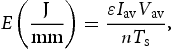
The microstructure was examined by optical microscopy (OM, ZEISS-Scope AI) and scanning electron microscopy (SEM, JSM-IT500A). The samples were etched with a solution (1 ml HF, 6 ml HNO3 and 100 ml H2O) for 10 s. X-ray diffraction (XRD, D/Max 2500PC), microhardness tester (Huayin, HVS-1000) and tensile testing machine (Instron 1121) were applied to analyse the phase composition and mechanical property. The tensile direction was parallel to the building direction. The tensile specimens with the dimension as described in the reference [3]. The fracture morphologies were analysed using the ultra-depth of field 3D microscope (VHX-950F) and SEM.
Results and discussion
Figure 2 shows the OM and SEM microstructures of TC11 alloys in Group I and Group II. It can be seen from the Figure 2(a–d) that the microstructures of the two groups of samples were needle-like basket structure but the size of α phase was significantly different. Compared with the sample in Group I, the length–width ratio of the α phase in Group II was large. The average length–width ratio of the α phase in Group I and Group II were 2.2 and 5.1, respectively. This was due to the increase of wire feeding in the Group II molten pool resulting in the decrease of heat input obtained by the single wire, and the slender needle α phase in the microstructure had not enough time to grow [8]. However, the heat input of Group I was larger, and the α phase truncated each other during the growth process, so that the aspect ratio of α phase increased and the α phase existed in the form of short rod.
OM and SEM microstructures of TC11 alloys: (a, b) Group I, (c, d) Group II.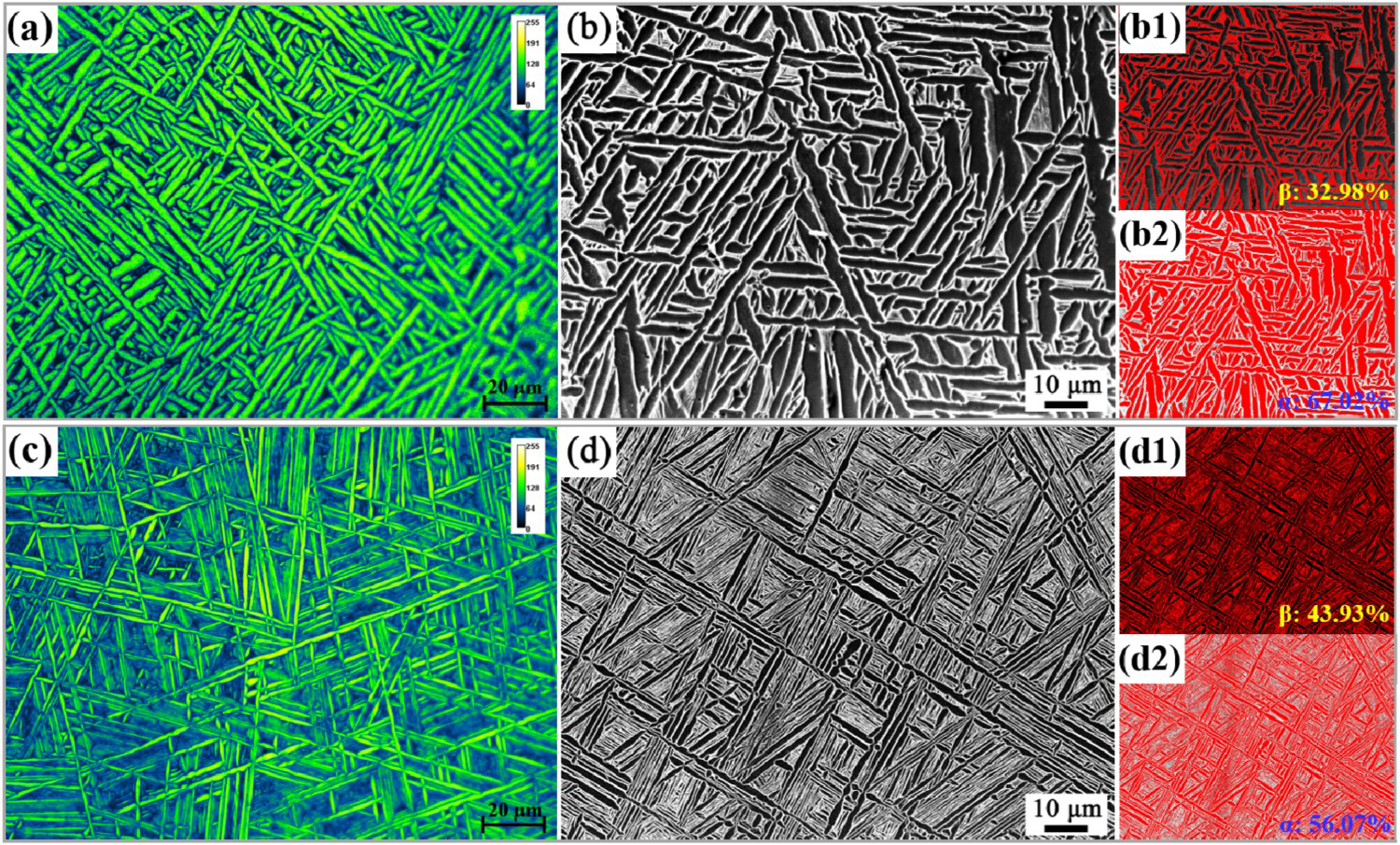
In addition, the proportion of β phase in Group II sample increased from 32.98% to 43.93% compared with the Group I sample. This was due to that the addition of welding wire reduced the heat input of the molten pool in Group II, refined the microstructure, and increased the volume fraction of β phase. It has been reported that the WAAM specimens with large length–width ratio α phase were easily to produce stress concentration at the interface of α/β phase during the process of tensile testing, resulting in cracks and its plasticity was reduced [9].
The XRD results of two group samples are displayed in Figure 3(a), from which it is evident that the phases of the obtained samples are consisted of α-Ti and β-Ti. The average microhardness of Group I and Group II were 382 and 407 HV, respectively, as shown in Figure 3(b). The stress–strain curves of the Group I and Group II tensile samples with the maximum tensile strength as shown in Figure 3(c). The average ultimate tensile strength (UTS) and total elongation (EL) of the sample of Group I were 922.01 MPa and 12.8%, and the average UTS and EL of Group II were 934.56 MPa and 10.56%, respectively. The α phase belongs to the close-packed hexagonal structure with three slip systems. The number of slip systems is small, and the slip deformation energy is poor [10]. During the sliding process, a large number of elongated α phases weaken the deformation coordination ability of the sample, resulting in a high strength of the Group II sample. In addition, the increase of α phase width will also lead to an increase in slip distance and a decrease in tensile strength. Meanwhile, the morphology of α phase changed from an elongated needle to a short rod, which weakened the damage to plasticity, resulting in a higher plasticity of Group I than Group II.
(a) XRD pattern of TC11 alloys, (b) Average microhardness of TC11 alloys, (c) Stress–strain curves of TC11 alloys.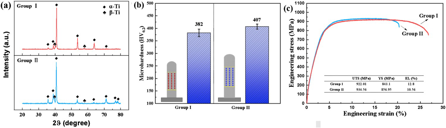
The tensile fracture diagram of TC11 alloy manufactured by WAAM is shown in Figure 4. It can be seen from the results that the necking degree of the tensile fracture surface of Group I was more obvious than that of Group II, as shown in Figure 4(a, d). It can be seen in Figure 4(b, e) that although the fracture surface of the sample in Group I was relatively flat, the height difference was larger than in Group II. There were dimples in the two groups of samples but many cleavage surfaces in the Group II sample were observed indicating that the fracture mechanism of Group II sample included ductile fracture and brittle fracture [11]. It can be seen in Figure 4(c, f), the dimple of the fracture surface of the samples in Group II were shallow but the dimples in Group I were large and deep, which further showed that the plasticity of the sample in Group I was better than that of the sample in Group II. In addition, it can be seen in Figure 4(e, f) that the presence of tearing edges made a certain height difference on the fracture surface. At the same time, there were some smaller dimples around the tearing edges, which indicated that the presence of partial tearing edges prevented the crack propagation during fracture. However, a small number of pore defects can be observed in Figure 4(f), which may be responsible for the reduced plasticity of Group II samples. Based on the above fracture morphology analysis, it can be concluded that the Group I sample was mainly ductile fracture and Group II sample was mixed fracture modes of ductile fracture and brittle fracture.
The low-magnification images and high-magnification SEM micrographs of tensile fracture surfaces of TC11 alloys: (a-c) Group I, (d-f) Group II.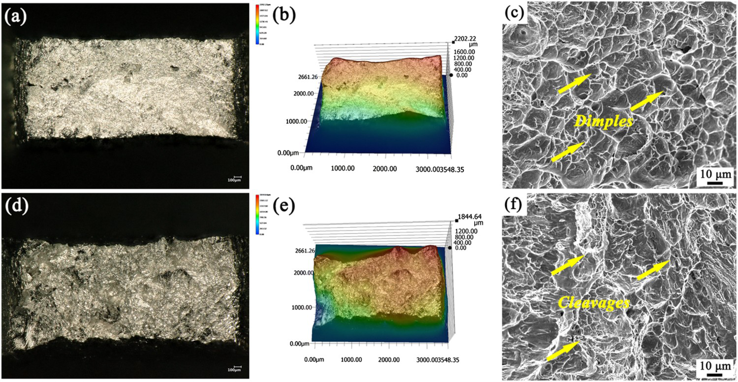
Conclusions
The two group TC11 alloy component was successfully fabricated by WAAM with single wire and multi wire, respectively. The MWAAM TC11 alloy exhibited more greater length–width ratio of basket structure than SWAAM sample. Adding the number of wire is an effect method to improve both deposition efficiency and hardness. The tensile strength of MWAAM TC11 alloy sample was improved within the acceptable range of plasticity reduction. The average UTS and EL of the MWAAM TC11 alloy sample were 934.56 MPa and 10.56%, respectively.
CRediT authorship contribution statement
P. F. Jiang: Conceptualisation, Investigation, Writing-original draft. R. Ji: Conceptualisation, Formal analysis, Writing-original draft. M. H. Nie: Investigation. X. M. Zong: Formal analysis. X. B. Wang: Investigation. Z. K. Chen: Data curation. C. Z. Liu: Formal analysis. Z. H. Zhang: Validation.
Declaration of competing interest
The authors declare that they have no known competing financial interests or personal relationships that could have appeared to influence the work reported in this paper.
Footnotes
Disclosure statement
No potential conflict of interest was reported by the author(s).
Correction Statement
This article has been corrected with minor changes. These changes do not impact the academic content of the article.