
Abstract
The present work simplifies the previous room-temperature quenching and partitioning (RT Q&P) process down to a single furnace cooling process, delivering a medium Mn steel with an ultimate tensile strength (UTS) of 1.7 GPa and a uniform elongation of 9.5%. The martensite tempering during furnace cooling is featured with slightly reduced dislocation density and is free of cementite precipitation, which is beneficial for ultrahigh UTS. Although the carbon partitioning is limited, the banded large austenite grains have proper mechanical stability owing to pre-existing high carbon content and the strong martensite matrix, allowing the gradual transformation-induced plasticity (TRIP) effect to enhance the work hardening behaviour and thus the good uniform elongation.
Introduction
Advanced high-strength steels (AHSSs) are developed to resolve the conflict between the weight reduction of automobile and improvement of the passenger safety [1,2]. The high strength of AHSS allows the structural components made thinner while maintaining the high performance of automobile during crash events. The strength of AHSS is mostly derived from hard martensite [3], which can be considered as the backbone. Martensite can be used either as the single dominated phase such as press hardening steels (PHSs) [4–6] or as the constituting phase such as quenching and partitioning (Q&P) steels [7–10]. Despite the high strength of martensite, it generally requires tempering to recover the proper ductility [11]. Tempering of martensite can take place during the martensitic transformation upon the quenching process which is known as the auto-tempering effect [12]. For instance, the martensite in PHSs could be subjected to the auto-tempering effect with the formation of cementite due to its relatively high martensite start (Ms) temperature (∼400°C) [13,14]. Tempering of martensite can also take place isothermally during the fabrication of AHSSs. For example, martensite is tempered during the partitioning process of Q&P steels at a temperature above or equivalent to Ms temperature [15,16]. Both auto-tempering and isothermal tempering jeopardise the key element of martensite, that is the high strength. Thus, trade-off must be made between the strength and ductility of martensite through conventional cooling process.
The martensite in Q&P steels is generated during the quenching process down to a temperature below Ms temperature and is tempered at an elevated temperature to allow carbon partitioning into austenite [7,9,17]. This Q&P process can be further simplified by selecting the quenching temperature as the room-temperature, leading to the development of room-temperature quenching and partitioning (RT Q&P) steel [18–21]. The RT Q&P process can effectively separate the quenching and partitioning processes, allowing the partitioning process to be done in appropriate time without instantaneous after the quenching process [18]. The design of RT Q&P steel is based on tuning of austenite stabilising elements so that optimal quenching temperature can be set as room temperature where proper amount of austenite is reserved [18,22]. However, this RT Q&P steel still requires further partitioning process to stabilise the austenite grains through C enrichment and reduce the residual internal stress of quenched martensite. The isothermal tempering at a temperature above Ms temperature as employed for processing of RT Q&P steels decreases the strength of martensite and thus the tensile strength of RT Q&P steels, reducing the capacity of Q&P steels in decreasing the weight of automobile.
Considering the possibility of partitioning process in largely reducing the strength of RT Q&P steel and the further simplification of RT Q&P process, the present work attempts to integrate the room temperature quenching and partitioning process into a single quenching process by using furnace cooling (FC). Such furnace cooling with retarded quenching rate applied in medium-Mn steels with high hardenability allows the formation of martensite without decomposing into other ferritic phases [23]. The martensite may be slightly tempered after its formation with suppression of cementite precipitation and minimised reduction of dislocation density during the FC process to maintain the ultrahigh strength of martensite. This FC procedure can avoid extra tempering process by utilising the waste heat of the steels after coiling or stacking and is thus facile and cost-effective. The microstructure and tensile properties of resultant steel treated by furnace cooling are characterised and discussed based on the comparison against the same steel composition treated by other processing counterparts.
Experiments
The chemical composition of medium Mn steel employed for the present investigation is Fe-10Mn-0.2C-2Al-0.1 V (in wt-%). The alloying of 10pct Mn content is to secure proper hardenability of steel so that sufficient amount of austenite is preserved after quenching down to room temperature [18–20]. The present medium Mn steel is prepared with a vacuum induction furnace and cast into ingots. These ingots are homogenised at 1150°C for 2 h, followed by hot forging down to a thickness of 12 mm, and finally hot rolling to produce strips with a thickness of 4 mm. The finishing temperature of hot rolling is about 850°C. The steel plates after hot rolling are reheated and isothermally held at 700°C for 1 h to soften the martensite matrix so that further cold rolling with approximate 50% thickness reduction (2 mm) is possible without the formation of cracks. Sub-standard tensile test samples with a gauge length of 32 mm and a width of 6 mm according to ASTM E8 are prepared from the cold rolled plates along the rolling direction (RD) by using wire electrical discharge machining. The tensile samples are austenitised at 900°C for 10 min and then quenched under different rates by using either water quenching (WQ) or furnace cooling down to room temperature (Figure 1(a)), generating WQ sample and FC sample. The cooling rate during water quenching by immersing in water is around 2200°C/s [24]. In contrast, the cooling rate during furnace cooling is much slower and the evolution of temperature generally follows an inverse proportional function with respect to time (Figure 1(b)). Some water-quenched and furnace-cooled samples are tempered at 300°C for 10 min to allow carbon partitioning, leading to the WQ-P sample and FC-P sample, respectively. The tensile properties of the present medium Mn steel treated with varied processing routes are measured using a universal tensile testing machine under a quasi-static strain rate of 10−3/s at room temperature. The macro-hardness of the present medium Mn steel is measured by Vickers hardness under a load of 1 kg. The nano-hardness of the constituting phases in the medium Mn steel treated with varied processing routes is characterised by using nanoindentation technique based on KLA iNano indenter armed with a diamond Berkovich indenter with a half angle of 65.3° under a maximum load of 2 mN. The spacing between the indents in the indentation matrix is 3 µm, which is large enough to avoid the influence of the prior indents on the subsequent indents. The position of the indents is identified by detailed scanning electron microscopy (SEM) observation. The overall microstructure of the present medium Mn steel is characterised by using SEM and electron back-scattering diffraction (EBSD) in Zeiss Merlin under a voltage of 15 kV. The samples for SEM/EBSD experiments and nanoindentation test are electro-polished in a mixture of 10% perchloric acid and 90% ethanol (vol.-%) at room temperature with a voltage of 18 V. The step size for EBSD scanning is 100 nm, and the data are processed using OIM analysis 7.0 software. The substructure of the present medium Mn steel is observed by transmission electron microscopy (TEM, FEI F30) under a voltage of 300 kV. The samples for TEM observation are prepared by mechanical thinning down to 50 µm and punched out to generate disks with 3 mm in diameter, followed by perforation using twin-jet electropolishing machine using a mixture of 5% perchloric acid and 95% ethanol (vol.-%) at −25°C with a voltage of 20 V. The dislocation density in the martensitic phase of the present medium Mn steel is calculated based on X-ray diffraction (XRD) profiles obtained from synchrotron X-ray diffraction measurement by using modified Williamson-Hall (MWH) method [25–28]. Synchrotron X-ray diffraction experiments were carried out in reflection mode at the beamline BL14B1 in Shanghai Synchrotron Radiation Facility. The energy of the monochromatic X-ray beam is 21.7 keV, corresponding to a wavelength of 0.5656 Å. To minimise the effect of strain layer, the surface of the samples for X-ray diffraction measurement is subjected to electro-polishing. The volume fraction of retained austenite (RA) in the present medium Mn steel is detected by the magnetic technique according to literature [29] and the magnetisation curves are measured with a vibrating sample magnetometer (VSM, lake shore 8604).
(a) Schematic illustration of the different thermal processing routes to treat the present medium Mn steel; (b) The evolution of the temperature inside the furnace chamber during furnace cooling (FC).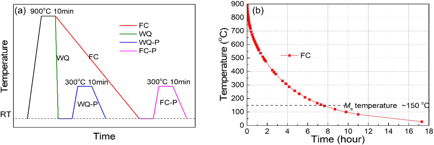
Results and discussions
The present steel treated by furnace cooling demonstrates a duplex microstructure with retained austenite grains embedded in the martensite matrix (Figure 2(a)). The enlarged view depicts the presence of large granular austenite grains (∼5 µm) and small lamellar austenite grains (Figure 2(b)). The large austenite grains are generally within retained austenite bands along the rolling direction while the small austenite grains are distributed individually between the martensitic laths (Figure 2(c)). The presence of large austenite grains could be ascribed to the segregation of Mn during the solidification process and possible larger C content within banded structure [30,31]. The small austenite grains have resulted from the intensive martensitic transformation, which can be stabilised through the ultrafine grain size, and high dislocation density owing to the accommodation of transformation strain [32]. The martensite in FC sample is free of cementite precipitations (Figure 2(b)), which may be due to the relatively low Ms temperature (∼150°C) as estimated based on empirical equations [33,34]. The low Ms temperature makes the precipitation of cementite from martensitic matrix ineffective after the initiation of martensitic transformation (Figure 1(b)). The present medium Mn steel effectively avoids the formation of proeutectoid ferrite or bainite during furnace cooling owing to sufficient high hardenability resulted from the presence of 10 pct Mn content. Similar to the FC sample, the WQ-P sample also exhibits a mixed microstructure consisting of martensite matrix and retained austenite grains with different sizes (Figure 2(d)). The large austenite grains are within the banded microstructure while the small austenite grains are distributed in the martensite matrix (Figure 2(e–f)). Thus, the formation mechanism of the austenite grains in the WQ-P sample should be the same as that of the FC sample. Nevertheless, substantial cementite precipitation in the martensite matrix is observed in the WQ-P sample (Figure 2(e)). Since the FC sample is free of cementite precipitation, it is reasonable to deduce that the formation of nano-sized precipitates is resulted from the isothermal tempering at 300°C for 10 min.
(a) SEM image of the present medium Mn steel treated by FC. (b) SEM image showing the magnified view of the dashed rectangle marked with b in (a). (c) EBSD phase image of the area marked with c in (a). (d) SEM image of the present medium Mn steel treated by WQ-P. (e) SEM image showing magnified view of the dashed rectangle marked with e in (d). (f) EBSD phase image of the area marked with f in (d). α′: martensite, γ: austenite, θ: cementite.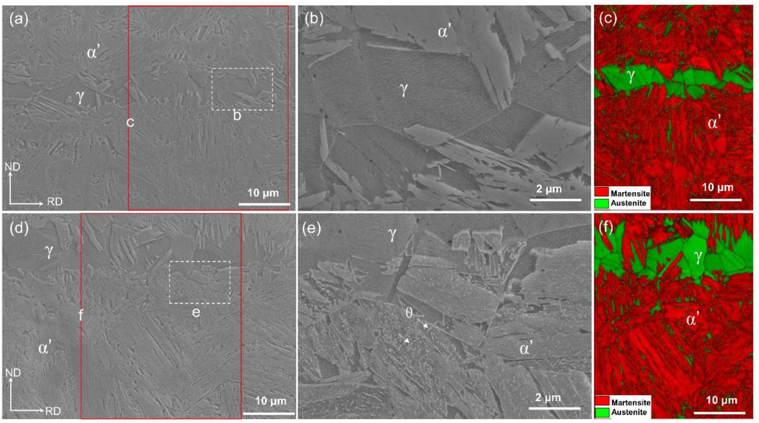
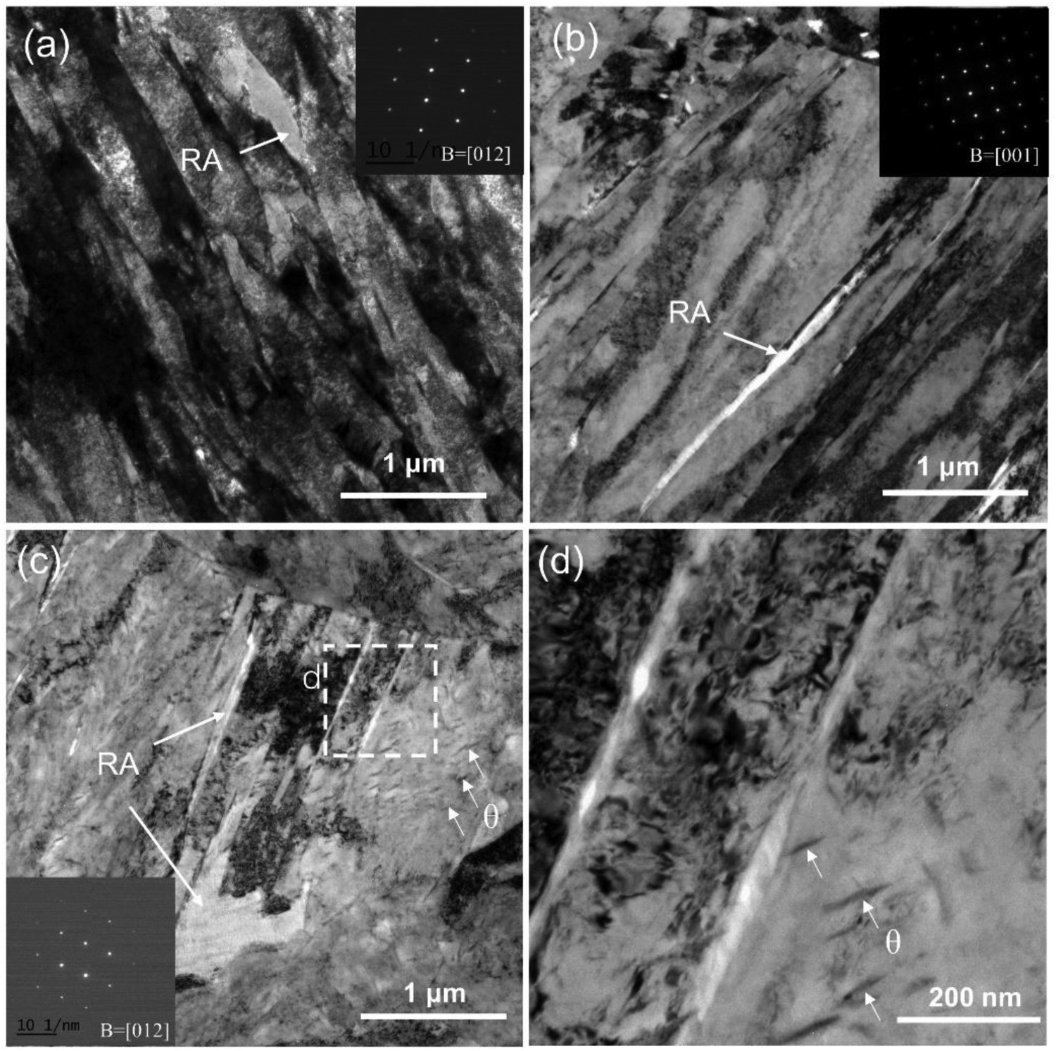
The substructure of the martensite lath in the present medium Mn steels treated by WQ, FC, and WQ-P is subjected to TEM observation (Figure 3). The WQ sample demonstrates typical lath martensite microstructure with high dislocation density (Figure 3(a)). The lath width of martensite is estimated to be around 250 nm, which is consistent with the literature report [35,36]. The lath morphology of martensite can still be observed in the FC sample (Figure 3(b)). The absence of cementite in the lath martensite in FC sample is also confirmed (Figure 3(b)). Interestingly, the RA grains can be occasionally detected (Figure 3), which is consistent with the SEM and EBSD observation (Figure 2). Different from the WQ and FC samples, coarse martensite laths decorated with cementite precipitations are observed in the WQ-P sample (Figure 3(c–d)), which is consistent with SEM observation (Figure 2(e)). Thus, the coalescence of martensite lath boundaries could take place simultaneously with the precipitation of cementite in WQ-P sample during the isothermal tempering process. No obvious precipitation of vanadium carbonitride is detected in these samples (Figure 3), which is in accord with other studies on tempering of V micro-alloyed martensitic steels at low temperatures [37,38], or aging of V-alloyed austenitic steels [39,40]. It seems that the dislocation density of WQ-P sample is smaller than that of WQ and FC sample (Figure 3). However, the precise determination of dislocation density is difficult owing to the heavily tangled appearance of dislocations, which can be resolved by synchrotron X-ray diffraction later.
The present medium Mn steels with varied processing routes demonstrate sharply different tensile behaviour (Figure 4(a)). The WQ sample has limited tensile ductility (∼3.6%), which could be due to the presence of large residual internal stress resulted from the martensitic transformation under fast quenching rate [41,42]. Irrespective of quenching rate, the partitioned samples demonstrate full development of tensile ductility with clear uniform and post-uniform elongations (Figure 4(a)). However, the tensile strength of the partitioned samples is lower than 1400 MPa (Figure 4(b)). Clearly, the FC sample represents the best combination of tensile strength and ductility among all these samples as depicted in Figure 4(b), with an ultimate tensile strength (UTS) of 1705MPa and a uniform elongation (UEL) of 9.5%. In addition, clear post-uniform elongation is also observed for FC sample but is absent in WQ sample (Figure 4(a)). Note that tensile strength is also related to the ductility. The limited tensile ductility does not allow the WQ sample to exhibit its full strength. Nevertheless, the results of Vickers hardness measurement show that the WQ sample has the highest hardness (Figure 4(c)), which is consistent with its fresh martensite state. The partitioning process reduces the hardness, which is consistent with the macroscopic tensile behaviour (Figure 4(b)). The work-hardening rate (WHR) of FC sample is much larger than the partitioned ones (WQ-P, FC-P) at the initial stage of the tensile deformation (Figure 4(d)). It is reported that the work-hardening rate at initial stage is mainly contributed from dislocation hardening [43], suggesting that the dislocation density in the present medium Mn steel treated by varied processing routes is different.
(a) Engineering stress-strain curves of the present medium Mn steel treated by different processing routes. (b) The corresponding tensile properties including ultimate tensile strength (UTS), total elongation (TEL), and uniform elongation (UEL) extracted from (a). (c) Vickers hardness of present medium Mn steel treated by different processing routes. Error bar in (c) represents the 95% confidence interval (CI) of 10 measurements. (d) Work hardening rate of the present medium Mn steel treated by WQ-P, FC, and FC-P. Note that the work hardening rate of WQ sample is not shown in (d) owing to its limited plasticity.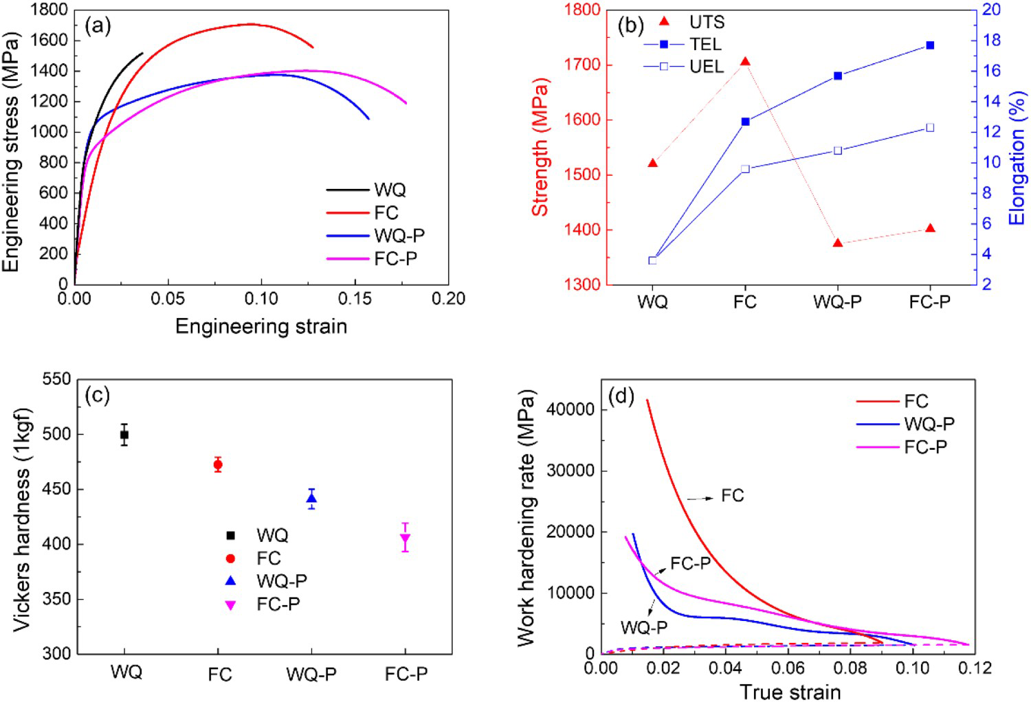
Since the WQ sample has limited tensile ductility and the partitioning process has a similar effect on the WQ and FC samples (Figure 4(a)), the comparison of the deformed microstructure is mainly carried out between the FC sample and WQ-P sample as shown in Figure 5. The large austenite grains in FC sample appear to be much smaller after the tensile test (Figure 5(a–b)), as compared to the ones without deformation (Figure 2(a–b)), confirming the transformation of austenite into martensite during the tensile deformation. Detailed EBSD measurement suggests that the residual austenite grains in the previously banded region remain partially transformed while the small austenite grains surrounded by the lath martensite almost fully transform into martensite (Figure 5(c)). Such transformation features are also observed in the WQ-P sample (Figure 5(d–f)). Note that the newly formed fresh martensite in the WQ-P sample can be clearly distinguished from the tempered martensite because the former is free of cementite (Figure 5(e)). The macroscopic transformation behaviour is characterised by using magnetic methods (Figure 5(g)). The volume fraction of RA in FC sample before tensile test is 12.9%, which is slightly smaller than that in WQ-P sample (16.9%) (Figure 5(h)). Nevertheless, the volume fraction of RA after tensile test decreases to about 3% for both FC and WQ-P samples (Figure 5(h)).
(a) SEM image of the present medium Mn steel treated by FC after tensile test. (b) Magnified view of the white dashed rectangle in (a). (c) EBSD phase image of the region corresponding to red solid rectangle in (a). (d) SEM images of the WQ-P sample after the tensile test. (e) Magnified view of white dashed rectangle in (d). α′t represents tempered martensite and α′f means fresh martensite. (f) EBSD phase image of the region corresponding to red solid rectangle in (d). (g) Magnetisation curves of the WQ, FC, WQ-P, deformed FC, and deformed WQ-P sample. (h) Volume fraction of retained austenite in FC and WQ-P sample before and after the tensile test calculated from the magnetisation curves.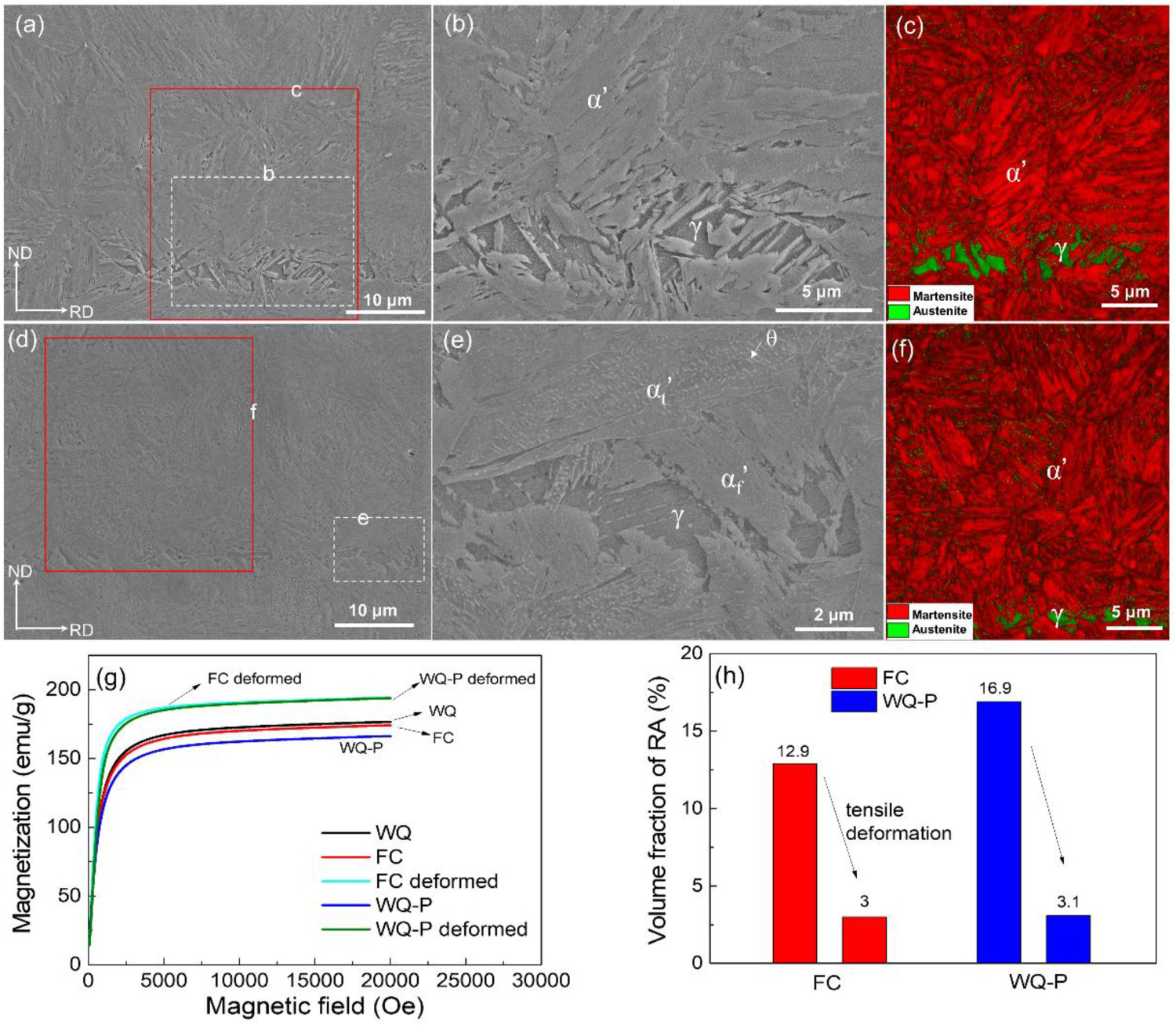
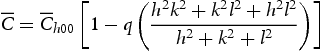
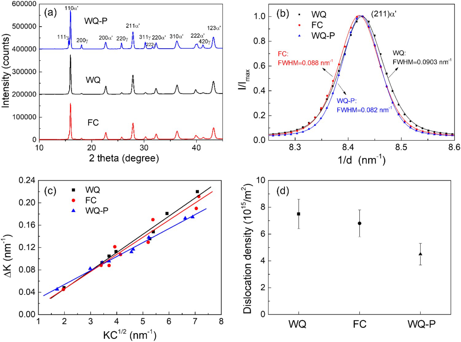
Besides cementite precipitation, the present medium Mn steel with different treatments demonstrates varied dislocation density as measured by synchrotron XRD test (Figure 6(a)). Considering the peaks of (211)α’, the full width at half maxima (FWHM) of FC sample is slightly smaller than that of WQ sample but is much larger than WQ-P sample (Figure 6(b)). Peak broadening could be induced by lattice defects such as dislocations [44], and has been utilised to calculate dislocation density by using modified Williamson-Hall (MWH) method in different studies [25–28]. According to the MWH method, the dislocation density ρ can be derived based on the following equation [28]:
(a) Synchrotron XRD profiles of WQ, FC, and WQ-P sample, α′: martensite, γ: austenite. (b) Enlarged peaks of (211)α’ and their full width at half maxima (FWHM). (c) The modified Williamson-Hall plots (ΔK versus KC1/2) for the different specimens. (d) The calculated dislocation density of martensite in the present medium Mn steel with different thermal processing routes. SEM images showing the indentation impressions on the martensite phase in (a) WQ, (b) FC, and (c) WQ-P samples. (d) Typical load-depth curves of the martensite phase in different samples. (e) Average nano-hardness of the martensite phase in different samples normalised with respect to that of WQ sample.
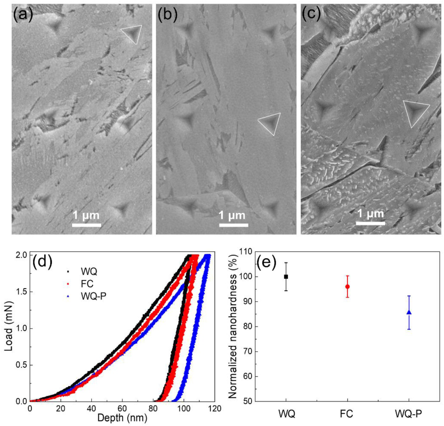
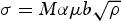
The strength of martensite is governed by dislocation density, block boundaries, interstitial atoms, and precipitations [11,46]. The intrinsic nanohardness of the martensite which is contributed by the strengthening defects within martensite blocks can be characterised by nanoindentation measurement [47]. Several nanoindentation matrices are performed on the martensite in WQ, FC, and WQ-P samples. The position of indentation impressions is identified by detailed SEM observation (Figure 7(a–c)). The indents close to the martensite block boundaries are disregarded for statistical analysis. The typical load-depth curves of martensite in the WQ, FC, and WQ-P samples are shown in Figure 7(d). Based on the load-depth curves, the nanohardness of martensite can be calculated according to the Oliver-Pharr method [48]. The normalised average nanohardness of martensite with respect to the WQ one is plotted in Figure 7(e). The intrinsic nanohardness of martensite in FC sample is around 5% smaller than that of WQ sample (Figure 7(e)), which is comparable to the estimated decreased strength (∼4.8%) based on the reduced dislocation density considering the Taylor hardening (Figure 6(d)). For Taylor hardening, the strength (σ) is proportional to the square root of dislocation density (ρ) [49]
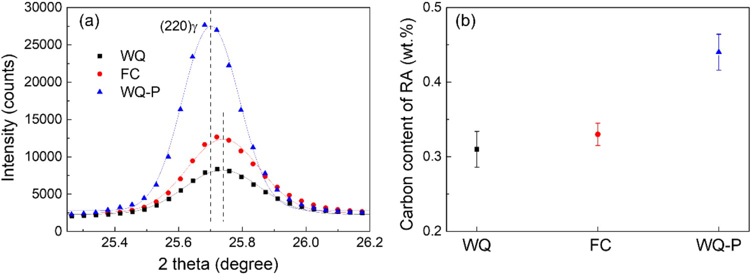
Carbon is a strong austenite stabiliser and the amount of carbon content in retained austenite grains can be calculated from the peak position of austenite in synchrotron XRD profiles. The representative peak position of (220)γ in the present medium Mn steel treated with varied processing routes is shown in Figure 8(a). As it shows, the peak position of austenite in WQ-P sample is shifted towards the lefthand side as compared to that of WQ and FC samples, suggesting that the retained austenite is carbon enriched after partitioning process. The carbon content of austenite can be determined based on the following equation [50]:
(a) Enlarged peaks of (220)γ showing the peak positions of austenite in WQ, FC, and WQ-P samples. The full synchrotron XRD profiles of the steels are shown in Figure 6(a). (b) The average carbon content of RA calculated from (220)γ, (111)γ, and (311)γ of the different samples.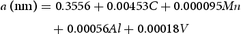
The FC sample demonstrates a moderate post-uniform elongation of 3%, which is slightly smaller than that of WQ-P sample (∼5%) but is obviously larger than that of WQ sample (0%) (Figure 4(a)). The post-uniform elongation is closely related to the fracture behaviour and could serve as an indication of fracture toughness. Thus, the fracture morphology of the present medium Mn steel is subjected to detailed SEM observation (Figure 9). The fracture surfaces of WQ sample exhibit brittle cleavage appearance (Figure 9(a–b)), which is consistent with the typical fresh martensite with no post-uniform elongation during tensile deformation. Although cleavage facets can occasionally be observed on the fracture surfaces of FC sample, a ductile fracture feature characterised of tiny dimples can be frequently detected (Figure 9(c–d)), which is consistent with its proper post-uniform elongation. The WQ-P sample shows a dominated ductile fracture with dimples across almost all the fracture surface (Figure 9(e–f)). The above fracture features suggest that the martensite in FC sample maintains at a medium state of tempering between that of the WQ sample and WQ-P sample, which is consistent with the mechanical testing (Figure 4) and microstructural observation (Figure 6).
SEM images showing the fracture morphology of WQ (a, b), FC (c, d), and WQ-P (e, f) samples. The lower left inset in (a, c, e) shows the overall fracture morphology of the tensile tested sample. The rectangle boxes in (a, c, e) mark the position for the magnified view observation as shown in (b), (d), and (f).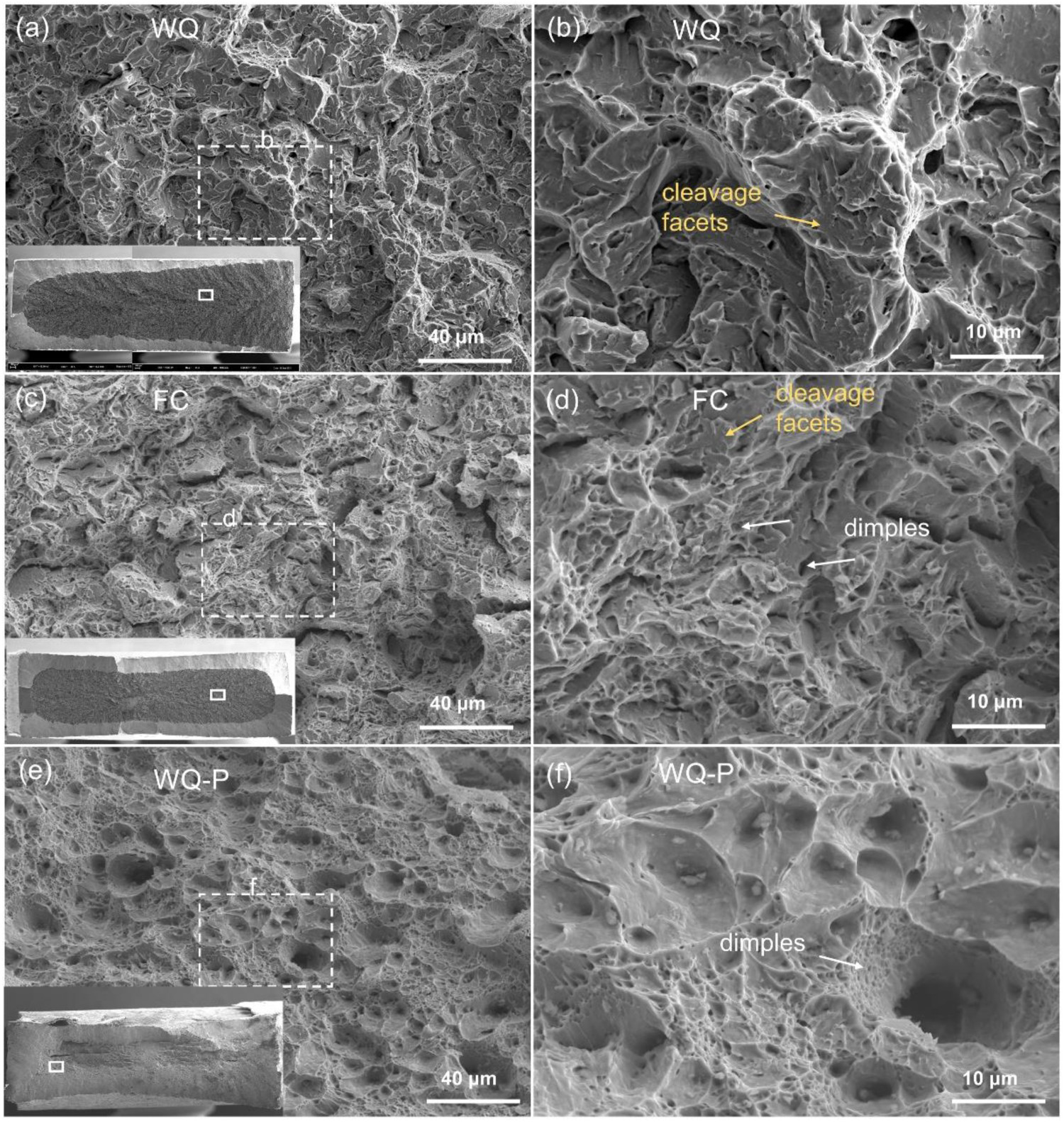
The tensile ductility of steels containing metastable austenite is closely related to the amount and mechanical stability of retained austenite grains [43]. This is because the amount and mechanical stability govern the capacity and the timing of transformation-induced plasticity (TRIP) effect to improve the work hardening prior to the necking process without nucleation of cracks [51]. The amount of austenite grains in Q&P steel is mainly determined by the quenching temperature since the partitioning process generally does not obviously change the austenite volume fraction given that the decomposition of austenite into bainite is absent during partitioning process. Here we set room temperature as the quenching temperature, which leads to a similar volume fraction of austenite grains in the WQ (11.7%) and FC (12.9%) samples. The mechanical stability of the austenite grains is governed by different factors, including chemical compositions (C/Mn) [52], grain size [53], morphology [54], adjacent matrix [55], and defect density [56,57]. Since the austenite volume fraction in WQ and FC samples is similar, it is expected that the mechanism of martensitic transformation during water quenching and furnace cooling should be the same. In other words, the grain size, morphology, and defect density of austenite grains among the WQ and FC samples are similar. Since the interstitial C partitioning between austenite and martensite is negligible, it is reasonable to expect that the partitioning of substitutional Mn atoms during furnace cooling should also be negligible due to the much lower diffusivity of Mn atoms [58,59]. Thus, the chemical compositions of austenite grains between the WQ and FC samples can be similar. Nevertheless, the tensile property of FC sample obviously outperforms that of WQ sample (Figure 4(a)). The analysis on the dislocation density in martensite based on the synchrotron XRD profiles suggests that the dislocation density is indeed reduced after furnace cooling as compared to water quenching. Such a decrease of dislocation density affects the matrix strength as reflected from the nanohardness measurement (Figure 7). Thus, it is believed that the change in matrix strength is the main factor affecting the austenite stability. The lower matrix strength in FC sample may facilitate the partitioning of more strain onto the austenite, as compared to the WQ sample in which the transformation of austenite may be prone to be shielded from the harder matrix, i.e. the shielding effect [55]. The austenite grains with high mechanical stability may not be able to transform into martensite to suppress the onset of necking on time. In addition, the controlled tempering of martensite matrix in FC sample may alleviate the internal stress which is believed to be detrimental to tensile ductility. Thus, as compared to WQ sample, the improved tensile ductility of FC sample can be ascribed to the controlled tempering of martensite matrix and the proper austenite stability on the aspect of matrix strength. In other words, this controlled tempering by furnace cooling effectively improves the ductility of martensite while maintaining a relatively high dislocation density for high tensile strength. The further partitioning at 300°C for 10 min applied on the WQ sample largely tempers the martensite with the formation of cementite and the substantial decrease of dislocation density. The austenite grains in WQ-P sample are also C enriched. The tempering process does not change the morphology and size of austenite grains. Fortunately, the pre-existing high C content of banded austenite grains contributes to the austenite stability of FC sample. In addition, the preservation of strong martensite matrix resulted from high dislocation density is also beneficial for the improved austenite stability of FC sample according to the shielding effect. Based on the above consideration, it is expected that the austenite stability in FC sample could be comparable to that of WQ-P sample, allowing the proper release of TRIP effect to enhance the work-hardening behaviour.
The present steel treated by furnace cooling demonstrates an ultrahigh strength of 1705 MPa and a uniform elongation of 9.5%, which outperforms the conventional PHSs such as 22MnB5 [4,14]. Such strength-ductility combination is enabled by controlling the tempering state of the martensite matrix. Cementite precipitation is suppressed in FC sample as confirmed from both SEM and TEM observations (Figure 2(b) and Figure 3(b)). Moreover, the dislocation density of FC sample is slightly reduced as compared to WQ sample but is still much higher than that of WQ-P sample (Figure 6(d)). The suppressed cementite precipitation and limited dislocation recovery during furnace cooling allow the preservation of high tensile strength, which is key for the weight reduction in automobile industry.
The non-isothermal tempering technique has already been used in low alloy steels by employing slow cooling after quenching to a certain temperature [60–62]. The benefit of non-isothermal tempering is to utilise the waste heat of the steel plates after coiling and is available to improve the ductility compared with the directly quenched ones [60,63]. However, such procedure appears to be difficult to obtain ultra-high strength in low alloy steels because of the pre-transformed ferrite and bainite [61,64,65]. Nevertheless, by utilising the RT Q&P steel with sufficient hardenability, the decomposition of austenite into ferrite during slow cooling can be avoided. Similar to the simple thermal-mechanical processing of PHSs, the present one-step furnace cooling is facile and cost-effective, which can be realised by utilising the waste heat of the RT Q&P steel after coiling or stacking. Therefore, the one-step furnace cooling with controlled tempering of martensite provides an alternative facile route to tailor the microstructure and optimise the mechanical properties of RT Q&P steel. In addition, the present work suggests that the partitioning process is not necessary to secure the high strength and good ductility of RT Q&P steel.
Conclusions
The present work investigates the microstructure and mechanical properties of medium Mn steel treated by single furnace cooling. The microstructure is characterised by SEM, EBSD, TEM, and synchrotron XRD. The mechanical properties are evaluated by using tensile test, Vickers hardness measurement, and nanoindentation test. The following conclusions are drawn based on the detailed comparison between the furnace-cooled sample and the same steel treated by other processing routes on the aspects of microstructure and mechanical properties.
The application of furnace cooling process does not change the volume fraction and C content of austenite grains as compared to the one treated by direct water quenching. Nevertheless, the detectable but limited dislocation recovery of martensite with slightly reduced nanohardness is found for the furnace-cooled sample as compared to the water-quenched sample. No cementite precipitation is observed in the furnace-cooled sample. Thus, the one-step furnace cooling can control the tempering state of martensite by selectively allow proper dislocation recovery while suppress cementite precipitation. The controlled tempering of martensite with high dislocation density and free of cementite precipitation ensures the high strength of medium Mn steel. The good tensile ductility of medium Mn steel is ascribed to the operation of TRIP effect from the retained austenite grains with proper mechanical stability derived from the strong martensite matrix and the pre-existing C segregation in banded austenite grains. In addition, the controlled tempering of martensite matrix may alleviate the residual internal stress which is believed to be detrimental to the tensile ductility. The conventional partitioning process during isothermal holding results in the substantial tempering of martensite with the formation of cementite and the largely decreased dislocation density. Despite the improved tensile ductility, the tensile strength of the medium Mn steel after partitioning process is decreased by more than 300 MPa as compared to the direct furnace-cooled sample.
Footnotes
Acknowledgements
B.B. He gratefully acknowledges the financial support from the National Natural Science Foundation of China (grant number U52071173), Science and Technology Innovation Commission of Shenzhen (Project No. JCYJ20210324120209026; KQTD2019092917250571), and Major Talent Programs of Guangdong Province (Contract No. 2019QN01C435). The authors would like to acknowledge the technical support from SUSTech Core Research Facilities.
Disclosure statement
No potential conflict of interest was reported by the author(s).
Data availability statements
The datasets generated during and/or analysed during the current study are available from the corresponding author upon reasonable request.