
Abstract
The present endeavour is to evaluate numerically and experimentally the influence of friction stir welding (FSW) parameters on peak temperatures, microstructures and mechanical properties of AZ91 magnesium alloy joints. A full 3D finite element ABAQUS model was developed to simulate the temperature distribution along the joint line. Therefrom, a total of nine different parametric combinations were derived for experimentations. Important insights relating to the material flow patterns and grain morphologies observed while altering the processing parameters have been elaborated. The parametric influence on the peak temperatures, grain morphologies, intermittent phases, tensile strength, and hardness are discussed through several mechanisms. Remarkably, the specimens prepared with the highest tool rotation speeds exhibited superior properties owing to several strengthening mechanisms.
Keywords
Introduction
Background
The global market size for magnesium alloys is almost 4000 million US dollars and is expected to grow by a whopping compound annual growth rate (CAGR) of 11.80% up to the year 2028 [1]. Such a stupendous market growth can be attributed to the rising demand for magnesium alloys from not only automotive and aerospace but electronics, defence, medical, and power tools industries too [2]. Moreover, the characteristics like a high strength-to-weight ratio and excellent vibration and shock damping make it a viable choice among other materials for lighter construction and applications. Magnesium alloys are 35% and 78% lighter than aluminium and steel, respectively [3]. Conversely, these alloys fall short on attributes like chemical resistance and weldability [4,5]. Recently, numerous ternary Mg alloys have been developed to address these deficiencies. AZ series ternary alloys possessing mainly aluminium and zinc constituents majorly find their applicability in industries. However, the joining of Mg alloys has been found complex owing to their highly reactive nature and inflammability [6,7]. As far as conventional fusion-based welding technologies are concerned, due to their uncontrollable thermal cycling nature, defects like solidification cracks, porosities, slag inclusion, etc., are inevitable in the resulting joints.
In the last two decades, friction stir welding (FSW), a solid-state welding process, has evolved as a promising technology for joining similar and dissimilar materials. This process majorly eradicates the defects associated with uncontrolled solidification commonly reported with fusion-base welding processes [8]. Apart from good microstructural integrity, high-speed welding, autogenous welding, and the need for semi-skilled human resources are among the most valued benefits of FSW in comparison to fusion-base welding methods [9,10]. To date, researchers have focused their investigations on finding effective parametric combinations for FSW joints and their influence on resulting microstructure and properties [11–15]. Majorly investigated parameters are axial tool pressure, tool rotation, traverse speed, etc. However, there is a lack of literature stating established relations between joint efficiency and parameters like tool rotation speed and traverse speed. It is well known that with the decrease in the ratio of tool traverse speed to rotation speed i.e. revolutionary pitch (RP), the heat input is increased during FSW. Further, the amount of heat input predicts the resulting microstructure in the weld zone (WZ), so the properties. On the one hand, Abbasi et al. [12] have reported an increase in the ultimate tensile strength (UTS) with lower heat input. Rouhi et al. [16] have investigated the influence of the welding environment on the UTS of FSW joints and reportedly higher UTS values were observed in the low-temperature water-cooled welding environment. On the other hand, Commin et al. [17] have reported a rise in the joint properties with an increase in the heat input. Afrin et al. [18] have also reported a rise in joint efficiencies with the rise in heat input that ensued from the increase in tool rotation rate. In a nutshell, heat input significantly influences the mechanical properties of FSW joints.
There are a few investigations for AZ91 alloy reporting the effect of heat input on joint efficiency, microstructure, and mechanical properties. The temperature distribution during FSW processes is directly associated with the heat input and has a significant influence on the mechanical properties and microstructure of weld joints. Song et al. [19] developed a heat transfer 3D model to compute the temperature distribution during FSW processes. They presumed that frictional heat is the reason behind the heat generated among the substrate and tool shoulder interface, and the plastic strain is negligible. Nandan et al. [20] and Zhang et al. [21] used a 3D numerical model to compute the material flow, temperature history, and mechanical features in FSW. Chao et al. [22] investigated the variations of temperature and heat input generated during the FSW process, and discover that only 5% of the heat produced during FSW flows to the tool. Singh and Dubey [23,24] experimentally investigated the weld characteristics during FSW of dissimilar AZ31 and AZ91 Mg alloys for varying processing parameters. They noticed that shoulder diameter and tool rotation rate were the most influencing parameters followed by welding speed in most of the cases. Xu et al. [25] applied pre-aging and high-force FSP to AZ91 alloy. They observed that the stir zone exhibited an enhanced yield strength due to grain refinement, dislocation strengthening, precipitate strengthening, and texture randomisation. Hassanamraji et al. [26] simulated deformation and heat transfer during FSP of AZ91 Mg alloy. Heat transfer, development of longitudinal, vertical, and lateral tool forces were assessed in detail by the developed model for cylindrical and conical pins. Hoda et al. [27] performed numerical modelling and experimental investigation of FSP on AZ91 to determine the influence of tool traverse speed and tool rotation on the thermal distribution attained during the process. They obtained a defect-free sample at a rotational rate of 1200 rev min−1 and a linear speed of 60 mm min−1. Abbasi et al. [28] studied the dynamic recrystallisation during friction stir vibration welding of AZ91 alloys. The grain size of the WZ is reduced as vibration is applied during FSW.
In this study, the influence of tool rotation rate (ω) and tool traverse speed (v) on peak temperature, joint efficiency, microstructure, and mechanical properties of FSWed AZ91 magnesium alloy was investigated numerically and experimentally. The peak temperature and temperature distribution during FSW of AZ91 magnesium alloy were simulated by a computational approach based on the ABAQUS code.
Finite element analysis
A computational approach based on ABAQUS (temperature–displacement explicit) was utilised to investigate the peak temperature of AZ91 Mg alloy joints produced by FSW. In this study, the thermophysical properties of the material with temperature changes were considered when calculating the temperature field [29], as shown in Figure 1.
Temperature-dependent thermal physical properties of AZ91 magnesium alloy.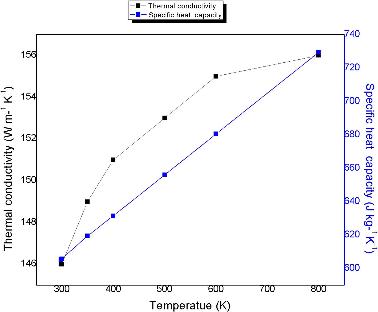
Referring to previous research [30,31], the heat conduction among the fixture and substrate plates can be modelled as equivalent thermal boundary conditions. In this model, the surface film coefficient (h = 12 W m−2 °C−1) was applied on the above and side surfaces of plates that were exposed to ambient air (ambient temperature = 25 °C) [32]. The heat transfer from the bottom surface of the substrate was controlled by the heat coefficient of 1000 W m−2 °C−1.
Figure 2(a) depicts the finite element (FE) model and its meshing used in this work. The FE model scale was 1:1. In this model, the substrate was modelled and meshed with C3D8RT eight-node trilinear displacement and thermally coupled brick element, and the tool is modelled and meshed with C3D4T four-node linear displacement and thermally coupled tetrahedron element. The total number of elements generated during meshing was 151599. The FSW tool has two primary functions: steering the material flow and heating the substrate through friction. The heat is induced by the friction among the substrates and the tool shoulder as well as by the plastic deformation in the vicinity of the tool during FSW. It is broadly acknowledged that the former was considered for most of the heat generated in FSW. In the preceding decades, various models have been developed to predict the temperature distributions in FSW. The heat source model is considered a vital aspect of FSW thermal analysis. In this model, frictional interaction between the rotating tool and the substrates was considered as a heat source. Surface–surface explicit interactions were considered between (i) tool pin and substrate abutting edges, (ii) tool shoulder and substrate top face. The friction coefficient of 0.3 at 25°C was assumed between the tool and the substrate for the penalty contact approach for this analysis.
(a) FEA model with meshing arrangement of the FSW tool and the substrate, (b) simulated model for friction stir welding of AZ91 mg alloy at Rotational speed 1070 rev min−1 and traverse speed 120 mm min−1, (c) schematic diagram showing locations of thermocouples.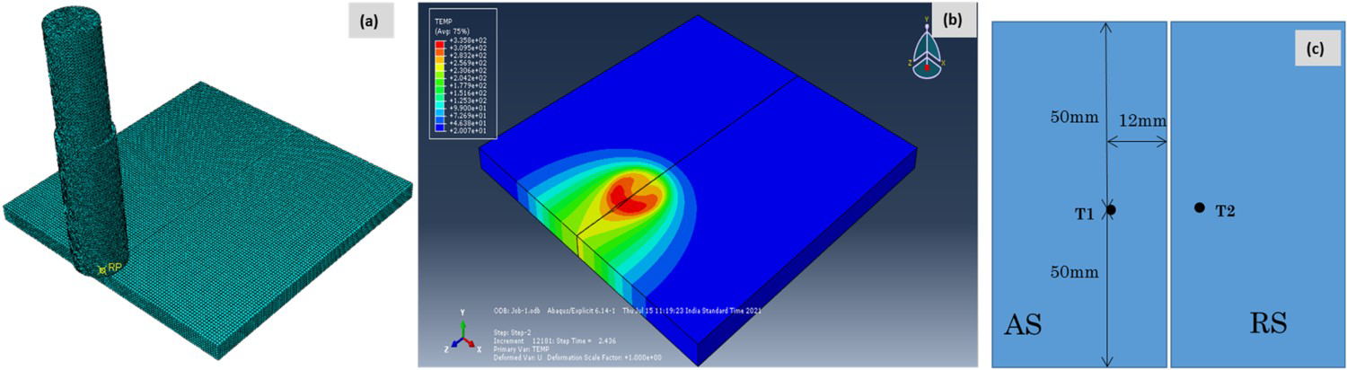
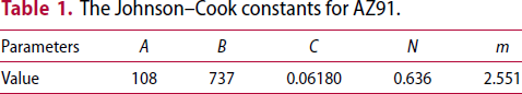
The Johnson–Cook constants for AZ91.
For FE analysis bottom and side surfaces of the substrate, plates were considered fixed constraints. Tool displacement was considered identical to experimental procedural stages: (i) plunge stage: 5.85 mm in a vertically downward direction; (ii) welding stage: 70 mm along the weld line.
Peak temperature during FSW of AZ91 predicted using numerical simulations.
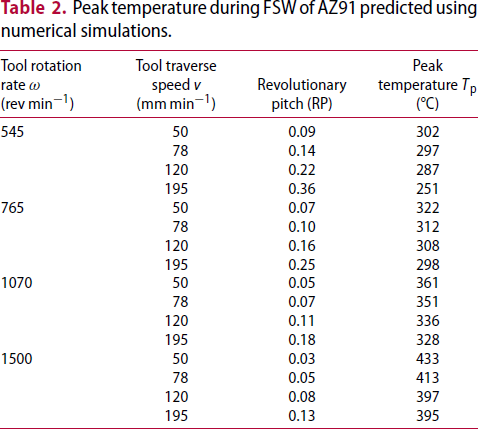
The parametric window for the current experimental campaign was designed with full consideration of the processing window of AZ91 reported for Mg alloy in previous investigations, RP and related thermal contribution, machine configurations, FSW simulations, and temperature analysis outcomes. For instance, Mishra et al. [38] in their review work established the processing window for FSW of different Mg alloys, and specifically for AZ91 Mg alloys RP ranging from 0.01 to 0.16 have been reported. Further, several researchers [36,38–47] considered the tool rotation and welding speed in the range of 700–1800 rev min−1 and 50–187 mm min−1 for their research work on FSW/FSP on AZ91 Mg alloy (RP: 0.02–0.26). Inline the present study incorporates an extensive process window comprising RP ranging from 0.03 to 0.36, making it an extensive and unique experimental campaign for future applications.
Materials and method
Materials
AZ91 magnesium alloy (Al 8.5 wt-%, Zn 1.3 wt-%, Mn 0.3 wt-%, Mg bal.) sheets sizing 100 × 50 × 6 mm were acquired through wire electric discharge machine (WEDM) from as-cast billet. All substrate plates were mechanically brushed, cleansed thoroughly using acetone, and dried in the air prior to welding to eliminate surface impurities.
Friction stir welding of AZ91
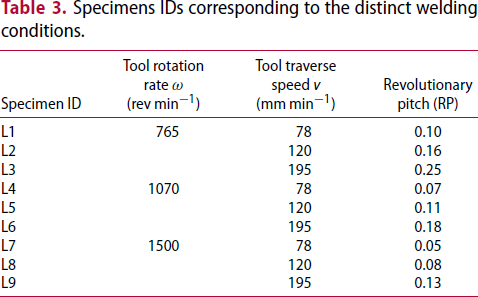
Specimens IDs corresponding to the distinct welding conditions.
Microstructural characterisation
Microstructure specimens were sectioned and further etched as per standard metallurgical testing procedure (ASTM E 3-01, E407, E1920). All the specimens were etched using Picral reagent. Thereafter, the microstructures of prepared specimens were characterised with optical microscopy (OM) (OLYMPUS, Model: Inverted Metallurgical Microscope GX51), scanning electron microscopy (SEM), and energy-dispersive spectrum (EDS) (Zeiss, Model: Ultra-55 SEM) to infer about the grain morphologies, defects, phases, intermetallics, etc.
Tensile strength and hardness testing
A total of three transverse tensile test specimens from each weld were prepared as per ASTM E-8M as represented in Figure 3. Uni-axial transverse tensile tests were carried out on an automated universal testing machine (Fine Spay Associates & Engineer Machine, India) at ambient temperature with a strain rate of 1 × 10⁻³ s−1 and a crosshead speed of 1.5 mm min−1.
Tensile test specimen prepared as per ASTM E-8 M.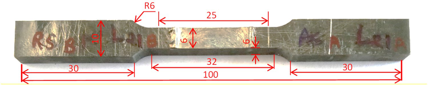
The microhardness of the prepared joints was carried out according to ASTM E-384 using Eseway 4302 Vickers hardness tester. Tests were undertaken using a square-based pyramid diamond indenter (136° intersects) at 300 g load and 10 s dwell time. Indentations for hardness measurements were mapped horizontally and vertically as well, with the distance between indentations ranging from 500 µm to 1 mm, for the prepared joints.
Results and discussion
Temperature measurement and analysis
The temperature vs time plots depicted in Figure 4(a) exhibit the temperatures on AS of the specimens prepared with different welding conditions. Likewise, the heating and cooling rate plots are displayed in Figure 4(b). The real-time temperature monitoring was carried out by installing a K-type thermocouple 12 mm away from the centre of the weld, as it was found quite difficult practically to measure the temperature at the centre of the weld. The temperature reportedly varies from the WZ to the 12 mm distance from the centre in the range of 90–100°C [48,49]. The same is reconfirmed with the graphical comparison of simulated and experimental results incorporated in Figure 4(c) for a representative specimen L7. From the plots, the highest Tp can be noticed with specimen L7 which was prepared with the highest ω (@ 1500 rev min−1) and lowest v (@ 78 mm min−1), whereas the lowest Tp can be noticed with specimen L3 prepared with the lowest ω (@ 765 rev min−1) and highest v (@ 195 mm min−1). On the one hand, the highest heating and cooling rates were recorded with specimen L7 which was welded with the highest ω and lowest v values. On the other hand, the lowest heating and cooling rates were recorded with the specimen L2 corresponding to the lowest ω and medium v values. Different heating/cooling rates for distinct specimens are not only attributed to the distinct frictional heat but plastic deformation that occurred while welding too. Mishra et al. [38] have discussed the substantial contribution of localised plastic deformation to the heat input during FSW. Additionally, as per the investigation by Hodowany et al. [50], the amount of heat dissipated by plastic deformation in AA 2024 substrate using Kolsky bar and servohydraulic testing, the alloy could consolidate ≥ 60% of the input plastic work in its microstructure regime. Thus, during FSW, the processing power input converted to plastic deformation energy in the bulk can be parted into two: (i) portion converted to heat and (ii) portion stored in the microstructure [51–53]. Moreover, as per the results published by Nemat et al., heat dissipated from plastic deformation may contribute 80–100% of the total heat input during FSW [50,54]. To summarise, it is not only the frictional heat engendered by the tool shoulder/substrate and tool pin/substrate interactions that contribute to the Tp, but the plastic deformation plays a significant role too, which greatly relies on the RP during FSW (Figure 4(b)). More importantly, heating and cooling rates leave a remarkable effect on the microstructure of the WZ.
(a) Temperature vs time plots of various samples during FSW by advancing side thermocouple; (b) heating and cooling rate of various FSW specimens; (c) comparison of simulated and experimental temperature profiles for Specimen L7.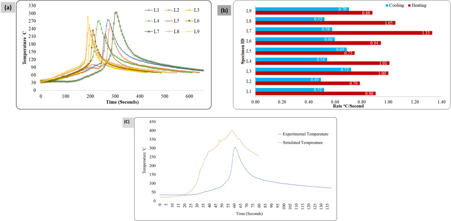
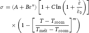
A detailed explanation model for average heat input during FSW reported by Frigaard et al. [55] can be expressed with the help of Equation (2):
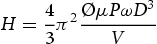
From Equation (1), it seems clear that the heat input is directly proportional to the ω and inversely proportional to v considering the rest parameters constant. This clearly explains the trend of the Tp discussed earlier in the section. However, the heating and cooling rates are substantially affected by other parameters like P, Ø, etc. The microstructure developed in the WZ and so the properties are largely depicted by these rates.
Macro and microstructure
Figure 5 displays macroscopic views of the specimens prepared with different welding conditions. The WZ shapes of almost all specimens seem identical to wine cups. The shape of WZ is majorly influenced by the substrate material flow stress and thermal conductivity [56]. Interestingly, with an increase in the values of v, the WZ width shrunk owing to the lower heat input with faster tool travel along the weld line reducing the tool residing time during FSW. A few specimens were characterised with macro and micro defects in the WZ owing to improper balance between the weld parameters. Specimens prepared with higher v values exhibited a higher number of defects like voids, porosities, and kissing bonds owing to insufficient heat input during FSW.
Macrostructures of specimens with different welding conditions.
The increase in the value of v reduces the tool residing time and so the material surrounding the tool pin cannot acquire sufficient momentum to complete its intended path from the advancing side (AS) to the retreating side (RS) leaving back the defects like voids, porosities, and kissing bonds. However, specimen L9 as an exception displayed almost defect-free WZ owing to the compensative heat input by the increase in the ω. Hence, it is critical to gain the proper heat balance during FSW.
Typical microstructures of different zones resulting post-FSW of AZ91 are demonstrated in Figure 6. As noticed, three different regions comprised of WZ, thermomechanically affected zone (TMAZ), and heat affected zone (HAZ) are visible with distinct microstructural features. The WZ was characterised by intensely refined microstructure resulting from dynamic recrystallisation (DRX), while TMAZ was characterised by severely distorted α-Mg grains consisting of several bands aligned tool pin periphery. A lean transition region between WZ and TMAZ can be observed in Figure 6. The aspect ratio of α-Mg grains gradually decreases while approaching TMAZ from the WZ owing to a lack of DRX in TMAZ [57]. No elongated alpha grains were observed in the HAZ region owing to the reduced amount of heat and strain input. In addition, the HAZ was characterised by a slightly coarser grain structure.
Material deformation patterns in different zones post-FSW.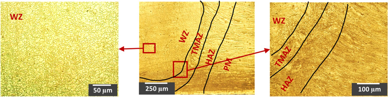
Grain refinement/recrystallisation
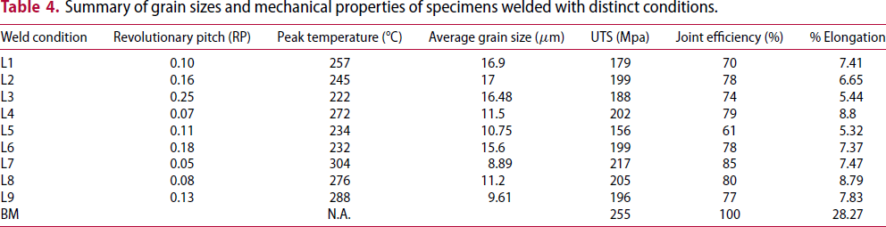
The grain structures of WZ for different specimens are exhibited in Figure 7. The average grain sizes were measured employing the line intercept method while the OM of the specimens. The grain sizes are summarised with RP, Tp, and UTS for respective specimens in Table 4 to understand the correlation among these parameters. Therefrom, the lowest grain sizes were recorded with specimens L7 and L9. Moreover, it is noteworthy that the specimens prepared with RP values 0.05–0.13 exhibited comparatively smaller grain sizes accompanied by higher Tp values. As reported by Sharma et al. [58], a faster cooling rate post-FSW leads to smaller grains attributed to the quenching effect in the WZ. Hence, process parameters largely affect the grain morphologies and so the resultant properties.
Grain morphologies of WZ for different welding specimens. Summary of grain sizes and mechanical properties of specimens welded with distinct conditions.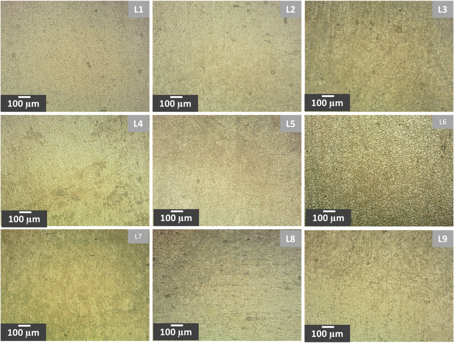
The grain sizes in the WZ were noticed from ∼6 to 18 µm with varying welding parameters. On the one side, decreasing RP promotes intensive plastic deformation leading to DRX and thereby grain refinement. On the other side, lower RP values induce more heat during FSW, which in course promotes the annealing effect and thereby grain coarsening. From the results summarised in Table 3, decreasing RP the contribution of DRX supersedes the annealing effect promoted by higher heat input during FSW. This is consistent with the results obtained in previous research [59–62]. Another reason for grain refinement with decreased RP could be the higher straining in the material that activates a larger amount of strain-free nucleation sites as described by Pareek et al. [63] engendering the nucleation of a higher number of grains per unit area.
Alternatively, the reason for the distinct grain sizes can be explained by the Zener –Hollomon parameter Z [64,65] represented by Equation (3):
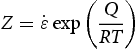
Further, 
The Zener–Hollomon parameter is often used to express the combined effect of strain rate and processing temperature on grain structure in warm or hot deformed metals and alloys. A few interesting studies including the one by Xu et al. [68] have reportedly established and reconfirmed the inverse relationship between Z and grain size by evaluating DRX grain sizes [69,70]. Here, it can be said that the temperature does not have a direct effect on the strain rate, and values of
SEM-EDS mapping and characterisation
The microstructure of the as-cast AZ91 is characterised by a primary α-phase, α + ββ eutectic structure composed of Mg solid solution, β β intermetallic compound (IMC) Mg17Al12 being distributed at the grain boundaries, and occasional Al8Mn5 IMC [71]. The primary cast structure of AZ91 transforms into the recrystallised fine-grain structure in the WZ with a lesser ββ -phase than the parent material (PM). From Figure 8, FSW resulted in significant break-up and dissolution of the coarse eutectic β -phase (Mg17Al12) that was previously distributed in the vicinity of grain boundaries. Besides, there is no α + β β eutectic in the microstructure of the WZ. In the welded specimens, no zinc was detected at the grain core or boundaries, clearly prompting dissolution into α-Mg and rupture/dissolution of ββ -phase. The SEM micrographs and corresponding EDS maps of important elements for specimen L7 (@ 1500 rev min−1; 78 mm min−1) are exhibited in Figure 9.
SEM micrographs of AZ91 alloy: (a) unprocessed parent metal; (b) weld zone of the specimen L7 (@ 1070 rev min−1; 78 mm min−1). SEM-EDS mapping of intermetallic compounds and phases present in specimen L7.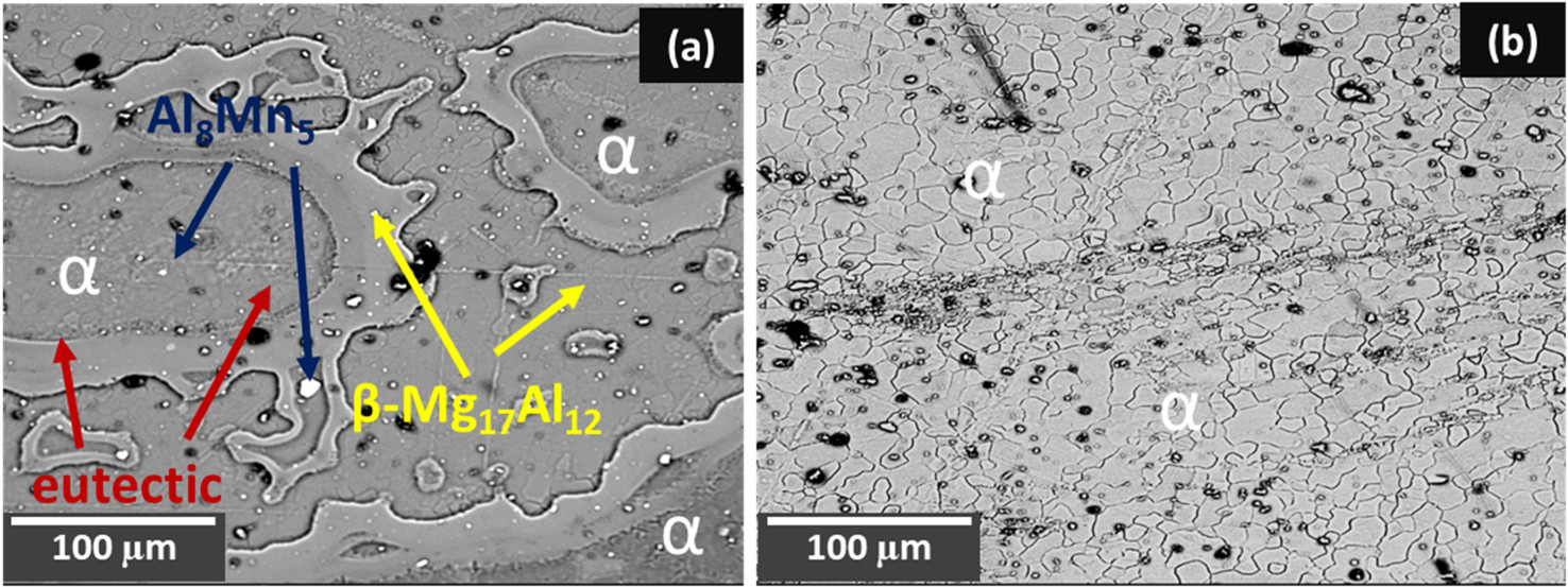
As per the Mg–Al phase diagram, once the alloy crosses 437°C, the dissolution of ββ -phase (Mg17Al12) into the Mg matrix is inevitable [72]. As per the Tp during different welding conditions discussed in Section “Temperature measurement and analysis”, the Tp recorded for specimen L7 was 304°C, which was recorded at 12 mm away from the centre of the weld. Hence, at the centre, it is likely to cross the 400°C mark during FSW. However, the complete dissolution of β phaseβ requires a hefty amount of time due to its large size and low diffusion rate of Al in the α-Mg. Here, it can be claimed that the dissolution has been initiated but not reached completely. Hence, as exhibited in Figure 8(a), very lean bands of ββ -phase have been confirmed by the EDS mapping. The IMC size measured in specimen L7 (@ 1500 rev min−1; 78 mm min−1) was in the range of 1.07–1.35 μm, whereas for specimen L9 (@ 1500 rev min−1; 195 mm min−1) which was welded at a high v value, exhibited much coarser IMCs owing to lesser heat input (lower Tp) ensuing in a lesser amount of dissolution.
Mechanical properties
Tensile strength
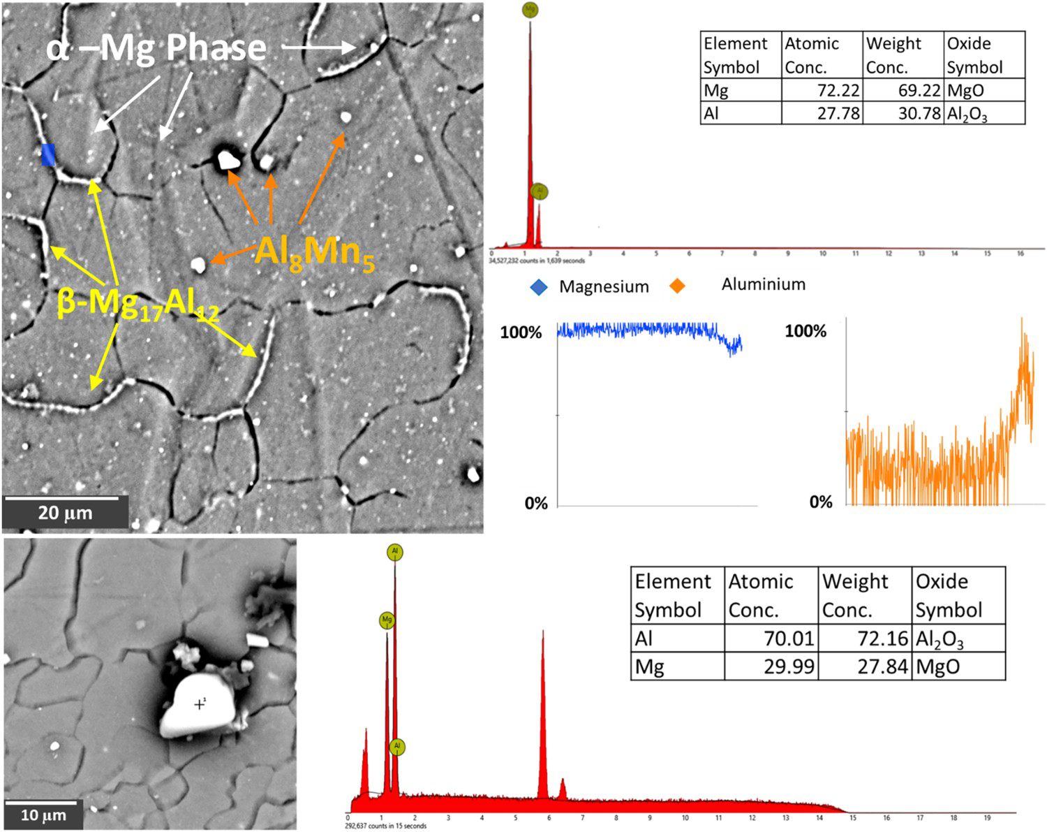
The UTS, % elongation, and joint efficiencies for distinct specimens are graphically represented and compared in Figure 10. It is seen that the UTS and % elongation of FSW joints were slightly reduced as compared to the PM. Park et al. [73] inferred that new crystallographic texture formation in WZ causes a decrease in UTS of FSW joints. Whereas Lin et al. [74] reported that the oxide layer formation in the boundaries between SZ and TMAZ resulted in a decrease in tensile properties. From Figure 10, the highest joint efficiency of 85% with the corresponding tensile strength of 217 ± 1.7 Mpa and elongation of 9.47 ± 0.88% was obtained with specimen L7 (@ 1500 rev min−1; 78 mm min−1). However, the specimens prepared with the highest ω of 1500 rev min−1 exhibited the highest UTS values, which is attributed to the grain refinement resulting from appropriate heat input, whereas the lowest joint efficiency of 61% with the corresponding tensile strength of 156 ± 38.4 Mpa and elongation of 5.32 ± 1.6% was obtained with specimen L5 (@ ω = 1070 rev min−1; 120 mm min−1). Caceres et al. [75] brought out that the strength of AZ91 alloys was determined by the combined effect of grain size, solid solutions, and precipitate strengthening. The increased strength of the L7 joint is a consequence, however, not only of grain refinement but also of the strengthening of the solid solution as a result of the dissolution of the ββ -Mg17Al12 phase into the magnesium matrix.
Tensile test results corresponding to distinct specimens.
In this study, IMC tends to be reduced owing to dissolution at elevated temperatures. According to the Mg–Al binary phase diagram, the Tp of SZ in this study is high enough for Mg17Al12 IMC to dissolve partly into the magnesium matrix. The highest value of UTS resulting from L7 (with an increase in heat input due to a high tool rotation rate (1500 rev min−1)) can be attributed to the highest dissolution of brittle IMCs like Al8Mn5 and ββ -phase (Mg17Al12). Moreover, the specimens welded with the highest ω of 1500 rev min−1 exhibited microstructure with the finest grains offering superior strength owing to the grain strengthening mechanism. Moreover, the fracture locations for each specimen are displayed in Figure 11. It is evident that except for the specimens prepared with the lowest ω of 765 rev min−1 (namely, L1, L2, and L3), almost all the specimens fractured from the centre of the WZ. Specimens L1, L2, and L3 are fractured from the WZ/TMAZ interface where the microstructure possesses maximum heterogeneity [76–79].
Fracture locations for the distinct specimens.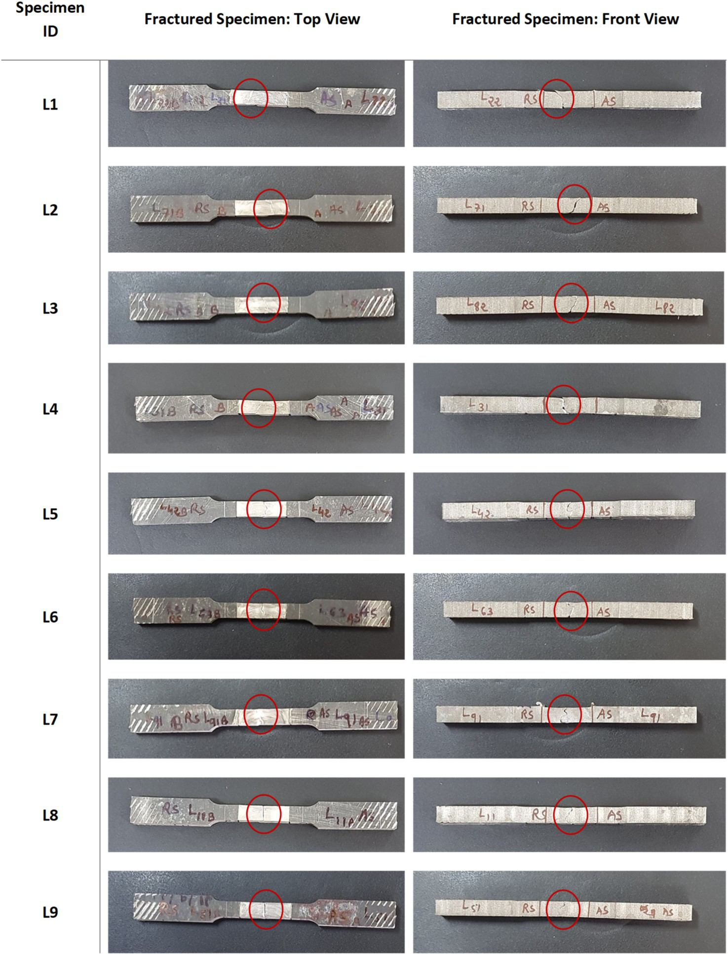
The nature of the fracture can be estimated from SEM micrographs of fractography exhibited in Figure 12. This fractography of PM illustrates the mixed mode of failure evidenced with dimples and quasi-cleavage facets which can be attributed to the large grain microstructure accompanied by brittle β β IMC (Mg17Al12) at the grain boundaries. Lee and Shin [80] noted that the crack and microvoids inception in the vicinity to ββ -IMC (Al12 Mg17) play an effective role in the fracture of AZ91 alloy. Nevertheless, numerous elongated dimples visible for weld produced with maximum heat input condition L7 (@ 1500 rev min−1; 78 mm min−1) signify the ductile failure.
Fractographic surface comparison of as-cast parent metal AZ91 and specimen L7 (@ 1500 rev min−1; 78 mm min−1).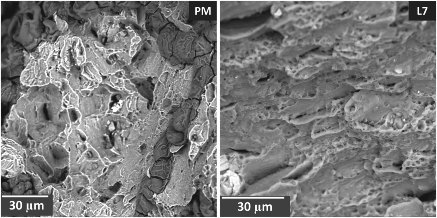
Microhardness
Microhardness evaluations were carried out for the specimens L7, L3, and L5 possessing the highest, average, and lowest UTS, respectively. The results are graphically represented in Figure 13. The hardness trend was found to be identical to the UTS results. An almost 20% rise in the hardness values for FSW specimen L7 was recorded in the WZ, whereas L3 and L5 specimens showed a marginal improvement in the hardness values. For all the specimens, there were sudden variations in the hardness values for the TMAZ and HAZ regions which may be attributed to the interaction with the IMCs and larger grain sizes. principally, three main mechanisms are believed to be responsible for such improvement in hardness values. First, the grains in the WZ of the specimens are much finer as compared to PM which plays a vital role in material strengthening. According to the Hall patch relations, hardness is inversely proportional to the grain sizes, signifying the higher hardness comparatively for FSW specimens [81–83]. Second, as per Orowan strengthening mechanism, the small IMCs present in the microstructure also contribute to the harness improvement [14,15,51,52]. Finally, as per the nature of the FSW process, extreme plastic deformation induces lots of dislocation in the microstructure of WZ, leading to higher dislocation density than the PM. These dislocations hinder the motion of cracks in the microstructure and offer higher mechanical properties [53,84]. However, IMCs play a limited role in hardness improvement as they are dissolved owing to high temperatures during FSW. Combined with the results of microstructure analysis, due to the effect of fine-grain strengthening, solid solution strengthening, and dispersion strengthening, the WZ has a higher hardness value.
Microhardness variation across the length of specimens L7, L5, and L3.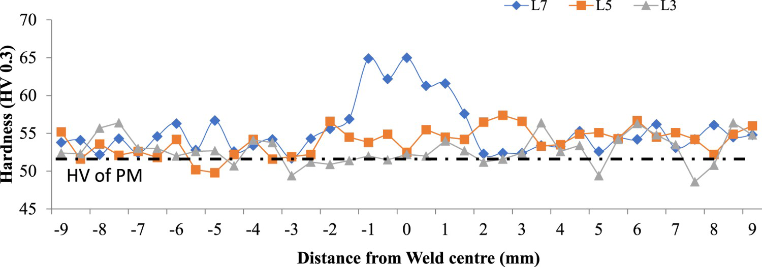
Conclusions
Through the present endeavour, the pivotal role of FSW parameters on the properties of prepared AZ91 joints has been elaborated using numerical and experimental analysis with important outcomes. To this end, influences of optimised nine combinations of tool rotation and traverse speeds on peak temperature, grain morphologies, intermittent phases, tensile strength, and hardness are discussed through several mechanisms. The followings conclusions were drawn:
Through the present investigation, it was possible to realise almost defect-free AZ91 FSW joints. Tool rotation rate was a crucial parameter affecting majorly peak temperature, grain morphologies, intermetallic, and mechanical properties. A positive correlation was established between tool rotation with defect omission and thereby properties of the joints. The welding specimens prepared with a revolutionary pitch ranging from 0.05 to 0.13 exhibited comparatively finer grain sizes accompanied by higher peak temperature values. Revolutionary pitch is one of the influential factors for the heat flux produced during FSW. The specimen welded with the highest tool rotation speeds exhibited superior properties owing to the greater extent of the dynamic recrystallisation. The highest joint efficiency of 85% was recorded with the specimen prepared with the highest tool rotation speed of 1500 rev min−1 and the lowest tool traverse speed of 78 mm min−1. Such superior joint performance can be attributed to the finest grain morphology resulting from dynamic recrystallisation along with the highest peak temperature leading to the dissolution of the majority of the brittle intermetallic like β β (Mg17Al12) and Al8Mn5. Fractography analysis revealed the ductile fracture for the best welding condition specimen (L7), whereas the combination of brittle and ductile fracture for PM. The specimen welded with a lower tool rotation speed combined with a higher traverse speed lacked the proper material momentum and temperature ensuing in defects like porosity, voids, kissing bonds, etc. The microhardness values were also in line with the tensile test results. However, only a marginal rise of 20% over PM was recorded with the specimen prepared with the tool rotation speed of 1500 rev min−1 and traverse speed of 78 mm min−1. Such a rise can be attributed to the grain strengthening, Orowan strengthening, and dislocation strengthening mechanisms.
Future recommendations for work and research
Experiments in this investigation were performed by altering only two parameters and finding the pivotal role of heat flux and dynamic recrystallisation. Future experiments can explore more hybrid approaches like in-process heating/cooling during FSW and extended numerical simulations delivering the grain morphologies.
Footnotes
Acknowledgements
The authors express their gratitude to the Mechanical workshop and welding research laboratory of Pandit Deendayal Energy University, Gandhinagar, India, for providing resources and support for completing this research work. Further gratitude to the Indian Space Research Organization, Government of India (in collaboration with Space Application Centre, Ahmedabad), for providing financial assistance for a project under RESPOND program (Project number – ISRO/RES/4/567/09-10). Under this project, a fully automatic three-axis vertical milling machine had been funded and used for experiments conducted.
We hereby declare that all authors contributed to the study's conception and design. The experimentation, material preparation, data collection, and analysis were performed by Ashish Desai, Vivek Patel, and Vishvesh Badheka. The first draft of the manuscript was written by Ashish Desai. Harikrishna Rana contributed to extra characterisation and manuscript revision. Bharat Khatri reviewed previous versions of the manuscript and provided valued suggestions. All authors read and approved the final manuscript.
We confirm that the manuscript has been approved by all authors for publication. I would like to declare on behalf of all co-authors that the work described herein is original research that has not been published previously.
Disclosure statement
No potential conflict of interest was reported by the author(s).