
Abstract
Rotating EDM and die sinking EDM were used to compare the machinability of MoSi2-SiC composites. Surface flaws such as micro cracks, un melted spherical particles, pores, a recast layer and craters following EDM can be attributed to the high hardness and poor toughness of the MoSi2-SiC. Die sinking EDM and rotary EDM, as shown by a comparison of recast layer thicknesses, produce the most uniformly thin white layers, at 92 and 30 µm respectively. The study found that the area fraction yield for porosity ranged from 8.18% to 12.922% when using rotary EDM, but only from 2.33% to 8.10% when using die-sinking EDM. According to the EDAX, the spongy exterior of a composite is the result of a lot of gas being produced. Although the rotational movement of the tool sweeps the resolidified particles away, Rotary EDM resulted in a thinner and less uniform recast layer while still producing good surfaces.
Introduction
Gong et al. [1] analysed that Electrical Discharge Machining (EDM) is a specialised form of non-contact machining. Material is removed by the transient high temperature generated by the spark discharge between the two poles of the pulse power source, which is where the workpiece and the tool electrode are located. Processing complex shapes can be performed with great efficiency, good precision, and low cost with this technology, which is not constrained by the hardness of materials. According to Selvarajan et al. [2] and Softah et al. [3], the efficiency and efficacy of machining may often be improved by using a non-traditional approach. Electrical discharge machining cannot be used on MoSi2 because of the material's poor conductivity. To increase the conductivity of MoSi2, SiC is utilised as a reinforcing material, and MoSi2-SiC is doped with ionic particles. Ming et al. [4] revealed that Electrical Discharge machining (EDM) of high-tech ceramics has various distinctive characteristics compared to metal machining. The discharge energy that is needed to melt and evaporate these materials is greater owing to their higher melting point. As a result of the increased likelihood of thermal stress during EDM of advanced ceramics, material loss is prevalent. Owing to the modern ceramics’ low resistance, the EDM method can only use a small range of pulse power settings. However, melting, evaporation, and thermal spalling are the main mechanisms of its elimination in a lengthy pulse width. EDM's process settings and the mechanical and physical qualities of the machined materials heavily influenced whether melting, evaporation, or thermal spalling was the mode of material removal. Electrical Discharge machining (EDM) of high-tech ceramics has various distinctive characteristics compared to metal machining. The discharge energy that is needed to melt and evaporate these materials is greater owing to their higher melting point. As a result of the increased likelihood of thermal stress during EDM of advanced ceramics, material loss is prevalent. Owing to the modern ceramics’ low resistance, the EDM method can only use a small range of pulse power settings. However, melting, evaporation, and thermal spalling are the main mechanisms of its elimination in a lengthy pulse width. EDM's process settings and the mechanical and physical qualities of the machined materials heavily influenced whether melting, evaporation, or thermal spalling was the mode of material removal.
Several factors, including current, pulse on time, pulse off time, gap voltage, etc., were studied to determine their effect on output performance by Gouda et al. [5] and Lin et al. [6], Processing time, surface quality, microscopic surface damage, and dimensional correctness are just a few examples of how these variables affect final product performance. It was shown that varying parameters like current, pulse on/off duration, gap voltage, and others can impact the final result. EDM may remove more material if the peak current and pulse duration are increased, but this can also hasten tool attrition and provide erratic results. In their study, Singh et al. [7] and Lee et al. [8] discovered that conductive ceramics could be treated well using the discharge machining technique, provided that the tool material was different from that of the workpiece.
According to Zhao et al. [9], molybdenum ceramic composite, an intermetallic metal with extraordinary performance for high-temperature applications, is used in a broad range of automotive and aerospace applications. Milled MoSi2 powder combined with silicon carbide particles showed remarkable mechanical capabilities, as reported by Paswan et al. [10]. The electrical resistivity, thermal conductivity, and melting temperature of the material are all factors in EDM processing, as pointed out by Ming et al. [11]. According to Jafarian [12], this is why conductive ceramics are so common in high-temperature applications such as heat exchangers, turbochargers, turbines, nozzles, and so on. Hongming et al. [13] reported that electrically conductive ceramic composites, which are essential in the aerospace and semiconductor sectors, may be hot-pressed from MoSi2 covered with SiC. To improve the ceramics’ conductivity and thermal stability, Lauwers et al. [14] investigated the effects of adding alumina to silicon nitride/zirconia matrices.
Selvarajan et al. [15] used a scanning electron microscope (SEM), X-ray diffraction (XRD), and energy dispersive spectrometer to analyse the surface microstructures produced by this novel technique (EDS). Ceramic composites of TiN, TiC, and TiB2 particles in a Si3N4 or Al2O3 matrix have been studied by Pradeep et al. [16], who described their conductivity behaviour. Alem et al. [17] discovered that microwave-sintered products had better mechanical characteristics than conventional, hot-pressed, and vacuum-sintered samples. Additionally, state-of-the-art studies have demonstrated that MMCs may be treated to microwave procedures to produce biological and electrical components. There was reportedly no response at the interface when SiC whiskers were used to chemically link MoSi2 composites, as reported by Zheng et al. [18]. This fortification process made it possible for the composites to function at temperatures as high as 12,000°C. Crack propagation, fracture toughness, and creep were all shown to be diminished once MoSi2-based composites were developed, as demonstrated by Petrovic et al. [19]. Mechanisms including ductile phase toughening, transformation toughening, second phase whiskers, matrix micro cracking, and particles are common in MoSi2-based composites. Because of its high melting point (2030°C), excellent thermal conductivity, low density (6.28 g cm−3), and good oxidation resistance and corrosion properties, molybdenum disilicide (MoSi2) was selected by Gao et al. [20] as a suitable ceramic composite material for use in high-temperature parts and components. Zakeri et al. [21] examined the fracture toughness and hardness of MoSi2, which has been reinforced with silicon carbide particles. It was determined that a specific volume percentage of SiC particles was ideal for the composite to have its exceptional rupture toughness. Selvarajan et al. [22] revealed that MoSi2-matrix nanocomposite materials fortified by SiC nanoparticles had improved electrical and thermal characteristics and flexural strength and discovered that adding titanium microparticles to dielectric increases surface hardness while also increasing conductivity and machining gap efficiency.
Conductive ceramic composites have been the focus of the vast majority of studies on electrically treated ceramics. While Selvarajan et al. [23] have established a small number of EDM parameters, the electroerodable properties of ZrO2-TiN and Al2O3-SiCw are also known. Selvarajan et al. [24] have found that the performance parameters of spark plasma hot pressing may be successfully improved. The results of a scanning electron microscope (SEM) study of Si3N4-TiN composites, reported by Selvarajan et al. [25], suggest that these materials may be beneficial in electrical discharge machining (EDM). The melting, oxidation, thermal spalling, electromagnetic, breakdown, electrostatic forces, and vaporisation features of MoSi2-SiC were studied to determine its material removal rates. While the impact of electrical discharge machining on ceramic composites is rather restricted, more study into the process's other characteristics is needed. The use of a magnetic field in the EDM process has several benefits, including the reduction of re-cast layer thickness and the enhancement of plasma flushing efficacy, as discussed by Shabgard et al. [26] and Husseina et al. [27]. Wang et al. [28] analyse several real-time data sets representative of whole EDM processes using chaotic numerical criteria such as power spectrum analysis, correlation dimension analysis, principal component analysis, and Lyapunov exponent analysis. The influence of spark action during MRR was studied by Mascaraque-Ramirez et al. [29] and Kang et al. [30], who analysed the surface morphology in terms of current strength and penetration depth, both of which have an impact on crater size. Dwivedi et al. [31] showed that tool rotation boosts MRR and surface finishing. The recast layer produced by rotational EDM is thinner than that produced by conventional EDM, despite the fact that a revolving tool produces greater dielectric mobility than a stationary one. To measure the material's performance, Duan et al. [32] devised a high-speed milling method to produce a white layer thickness. According to Arfaoui et al, [33] the white layer's thickness is determined by the cutting edge's chamfer size, radius, heat conductivity, and material hardness. According to recent research by Das et al. [34], several investigations have looked into spark EDM's effect on surface quality by using a copper composite electrode. Studies have been conducted on EDMed in terms of surface roughness, microhardness, microstructure, and elemental composition. Micro structural and elemental composition analyses confirmed that elemental tool residues remained in the workpiece following an EDMed operation, as reported by Mandal et al. [35]. Using scanning electron microscopy (SEM), Srinivasan et al. [36] examined the recast layer and found several surface flaws, such as microscopic holes, scraps, drops, clusters, and indentations. According to the research carried out by Zhang et al. [37], carbon is mainly generated by SiC particles and the decomposition of kerosene oil/EDM oil during the EDM process due to the oil's high molecular hydrocarbon content and high volatility, while oxygen originates from air and the decomposition of the oil.
Evidenced by the aforementioned literature, it is clear that only a few researchers have attempted to study the investigation of the surface and sub-surface of topography of the intermetallic ceramic composite of MoSi2-SiC after the EDM process. The quantity of imperfections on the final surface is directly related to the EDM process's final outcomes.
This study set out to fill that gap in knowledge by investigating the surface topography of electrically discharge-machined conductive ceramic composites produced by rotary and die-sinking processes. The authors of this study sought, by scanning electron microscopy (SEM) investigation of cross-sections of electrical discharge machining surfaces, to gain insight into the deterioration of materials in rotary and die-sinking EDM techniques for ceramics. Furthermore, they examined the erosion and subsurface damage caused by various EDM boundaries and materials. The EDAX report was then used to conduct additional analysis of the surface topography for each category of hole machined by rotary and die-sinking EDM. Eventually, the purpose of the research was to quantify the surface porosity of EDMed ceramic composites produced using rotary and die-sinking processes. Although this is based on an in-depth investigation of academic research on EDM of surface topography of composites, very little work has been performed on the MoSi2-SiC conductive ceramic composite's average surface roughness analysis and a video measuring machine were used to quantify the taper angle, respectively.
Material and methods
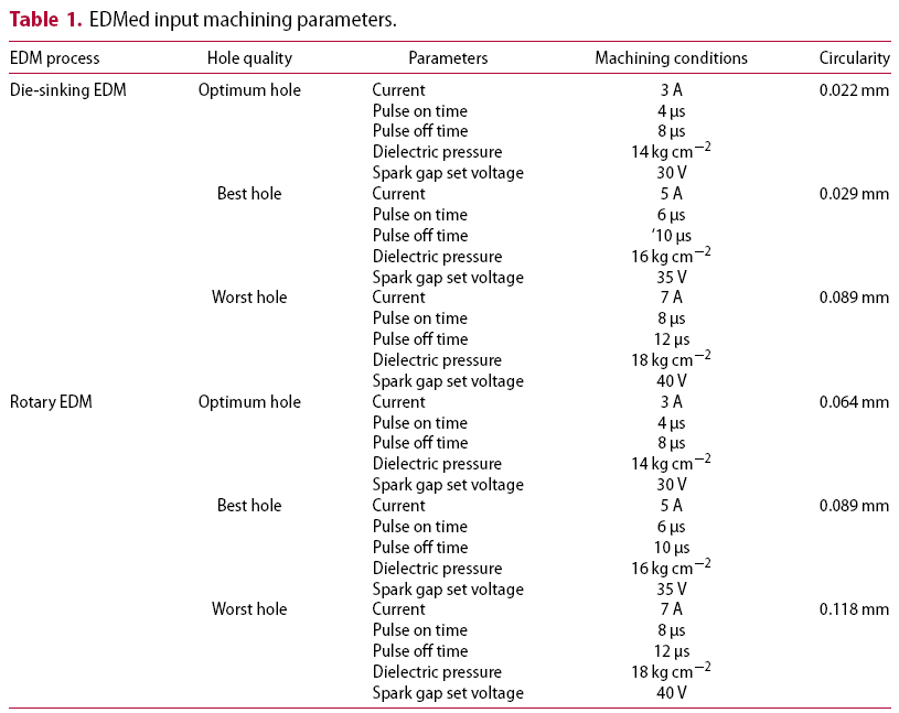
EDMed input machining parameters.
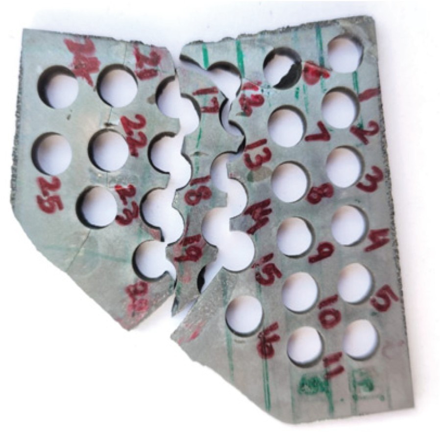
Cracks, micro holes, and craters were all visible in the SEM pictures of EDMed MoSi2-SiC surfaces. The sparking procedure created enough heat to trigger these flaws. Surface characterisation revealed micro-sized features such as craters, debris, resolidified material, and micro-voids. Micro cracks, deep craters, a shallow matte look, holes, and spherical debris particles all contributed to the surface's complex appearance and uneven topography caused by craters and debris. Peak current and pulse-on time were shown to be the two most influential elements in surface accuracy. The amount of thermal power utilised for machining is dependent on the available supply. Pulse-on times that allow for more material to be melted and evaporated result in greater heat energy being transferred into the workpiece. Resolidified material, debris, micro-voids, and craters on the EDMed surface can contribute to its roughness. Cracks of varying sizes appeared on the machined surface in the form of macro cracks, micro-cracks, pockmarks, and disintegration zones. With increasing machining powers and per-pulse energies, the surface becomes less homogenous and the cracks get wider and denser, making the characteristics dependent on the machining settings. Figure 1 (a) shows the image of OSCARMAX SD325ZNC Die sinking EDM machine and 1 (b) shows the image of OSCARMAX SD350ZNC Rotary EDM machine. Figure 2 shows the image of machined work piece of ceramic composite.
(a) Image of OscarmaxSD325ZNC Die sinking EDM machine (b) Image of OscarmaxSD350ZNC Rotary EDM machine. Image of machine workpiece of MoSi2-SiC ceramic Composite.
Results and discussion
Micro structural analysis of MoSi2-SiC ceramic-based composite: Die-sinking EDM
Micro structural analysis of the optimum hole in MoSi2-SiC composites by die-sinking EDM
Die sinking electrical discharge machining (EDM) was used to create the topography in Figure 3 of the MoSi2-SiC composite. Multi-response optimisation was used to get the best values for the EDM process parameters. Figure 3(a) shows that melting and evaporation are the main mechanism of material removal, with a minor amount of the evaporated material being redeposited as a recast layer. The electrical arc created between the electrode and the workpiece created the craters seen in the picture. Surface crater size is primarily determined by the discharge energy, which is in turn a function of the machining parameters. These craters have an average diameter of 36.2 µm, and the graphic also depicts a few microscopic holes with an average size of 3 µm. In Figure 3 of the EDAX study, the low percentage of oxygen (less than 10% by mass) corroborates these findings. Micro cracks on the machined surface didn't appear since the optimum machining conditions were used. The white or recast layer is visible in the vertical cross-section of the machined surface shown in Figure 3(b). The recast deposit averaged 92 µm in thickness.
(a) Micro structure of machined surface and (b) cross-sectional area of MoSi2-SiC ceramic-based composite of the optimum hole by die-sinking EDM.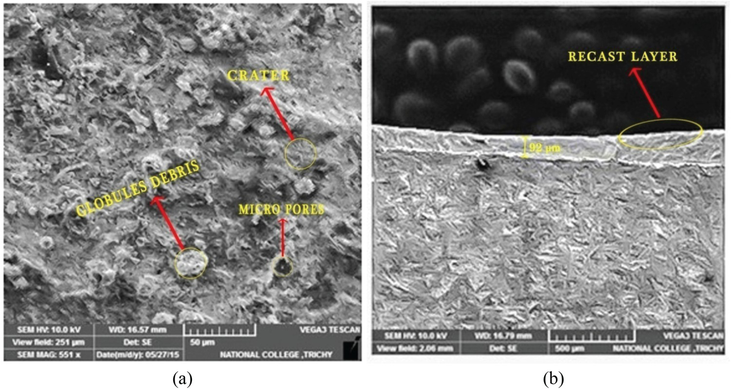
Surface defect by EDAX analysis: Crater for optimum hole on MoSi2-SiC composites for die-sinking EDM
The craters (surface imperfections) on the machined surface of the MoSi2-SiC composite are shown in Figure 4 as a consequence of multi-objective optimisation of the die-sinking EDM process to obtain an optimal hole. High thermal energy and peak current are thought to be responsible for crater formation. Table 2 shows the EDAX make-up of the crater's uneven surface.
(a) Crater on the machined MoSi2-SiC composite for the Optimum hole & (b) EDAX composition study of surface flaws (die-sinking EDM). EDAX analysis to ensure the optimum hole (die-sinking EDM).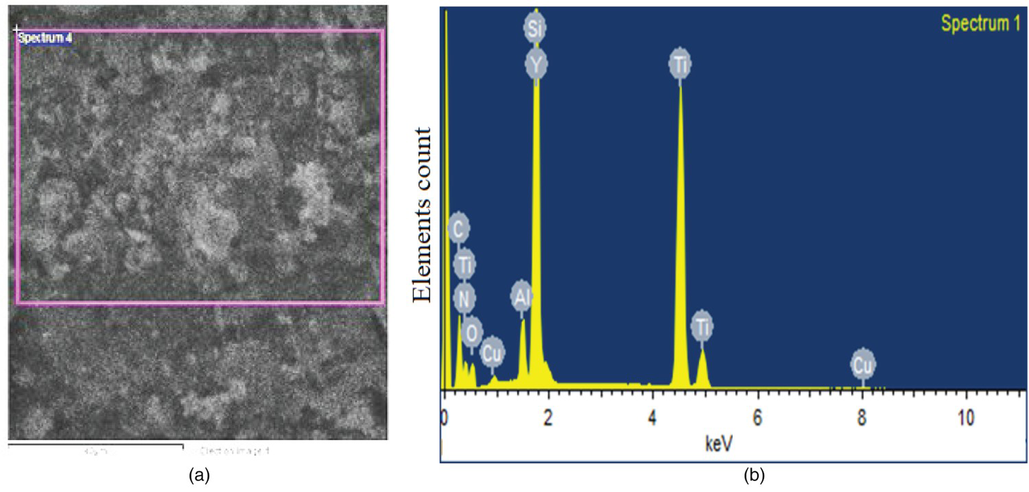
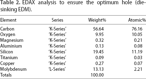
The sub-surface of the MoSi2-SiC composite can be seen under the modified layer, and it is smooth with black holes. The EDAX report shown in Figure 4 and Table 2 provides proof of this. The EDAX results, which indicate over 10% oxygen by weight, corroborate the hypothesis that the machined surface has few holes.
Micro structural analysis of best hole in MoSi2-SiC composite by die-sinking EDM
Die sinking EDM was used to machine (best hole) MoSi2-SiC ceramic-based composites, and their cross-sectional area and microstructure are shown in Figure 5(a). Little craters of an average size of 8 µm may be seen on the machined surface, as shown by the topography. And also in addition to improving surface quality, a wider discharge gap reduces the heat flux, so less material is removed by a single spark. Figure 5(b) depicts the median recast thickness of the modified layer, which is 100 µm. As compared to a recast layer created with optimal settings, the updated layer is deeper.
(a) Micro structure of the machined surfaceand (b) cross-sectional area of MoSi2-SiC ceramic-based composite's by die-sinking EDM for best hole.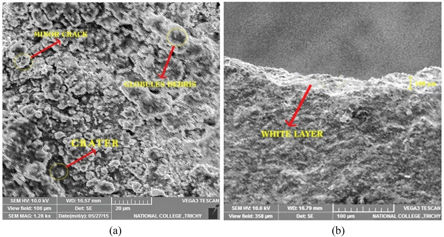
EDAX investigation of best hole on MoSi2-SiC composites by die-sinking EDM
Surface flaws (Micro crack) on the machined surface of the MoSi2-SiC composite for the best hole created by die-sinking EDM are shown in Figure 6. Micro cracking occurred during machining due to the combined effects of tensile and thermal stresses. It is well-known that these micro cracks degrade the material's corrosion and endurance to fatigue. Therefore, the quality of the surface should be the most significant criterion used to evaluate the effectiveness of the die-sinking EDM technology. Table 3 displays the composition of EDAX that causes the surface defect seen in micro cracks.
EDAX analysis of machined MoSi2-SiC composite of best hole (die-sinking EDM). EDAX analysis of surface defects (Micro crack) of MoSi2-SiC work specimens for best hole (die-sinking EDM).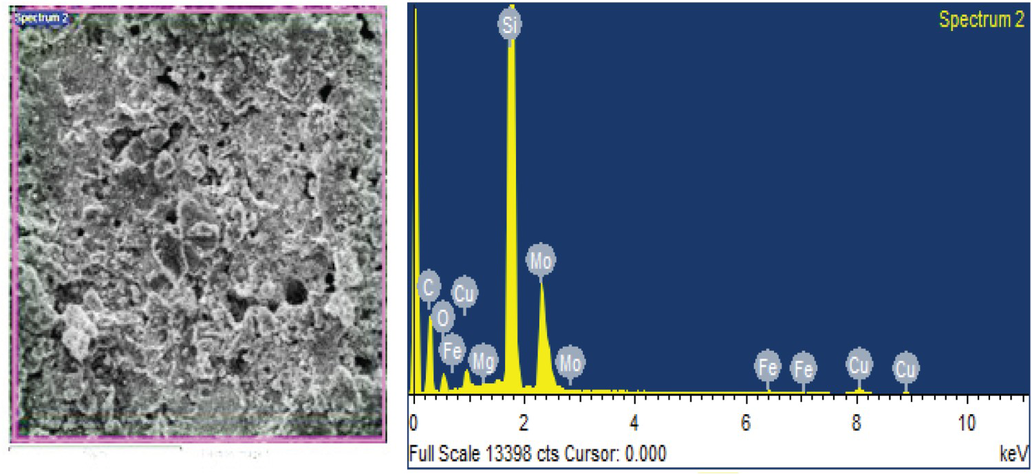
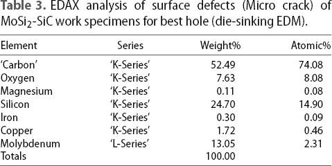
The EDAX analysis of this surface confirms the presence of decomposed carbon and silicon on the treated work material (see Figure 6 and Table 3). During the EDM process, the copper electrode melts and resolidifies, resulting in 1.72% copper content. Copper's excellent thermal conductivity and ductility allow for an electrode with a thinner affected layer and reduced cracking. While the ideal machining conditions are used, there are still signs of micro crack formation.
Micro structural analysis of worst hole of the MoSi2-SiC composite by die-sinking EDM
Figure 7(a) depicts the micro structural characterisation of a MoSi2-SiC workpiece machined with a die-sinking EDM process and EDM settings that corresponded to the worst hole. The treated surfaces have been seen to include craters and major fractures all over. Metal removal in EDM of MoSi2-SiC composites occurs by evaporation, thermal spalling, and melting. This spalling effect emerged as a direct result of the recently produced substantial fractures throughout the EDM process. These bigger micro cracks facilitate the separation of a bulk during subsequent pulse delivery. However, because the spark intensity is retained in the spark location for a longer period of time before the material can dissipate the energy to the surrounding areas, a material with a poor conductivity value, such as MoSi2-SiC, might be expected to have a thicker impacted layer with more cracking.
(a) Microstructural analysis and (b) cross-sectional area of MoSi2-Sic composite of worst hole (die-sinking EDM).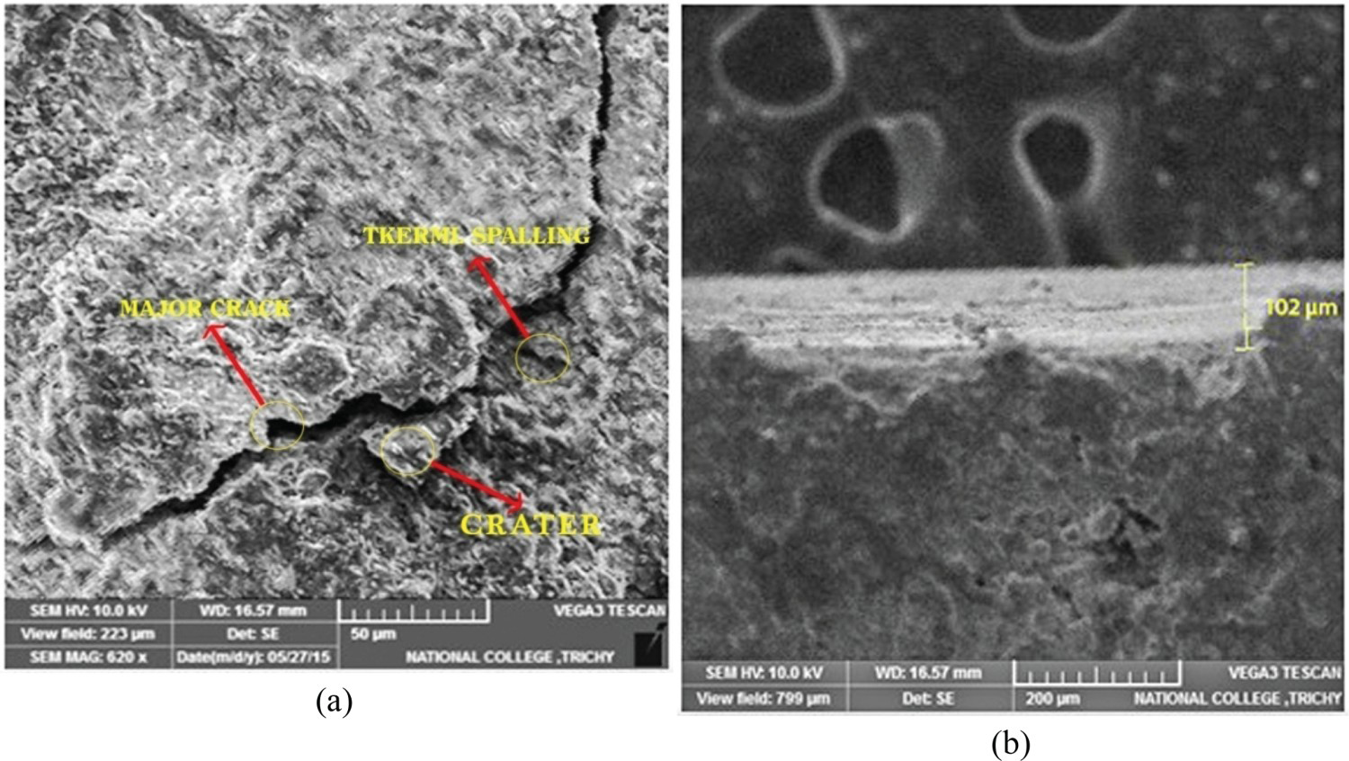
The largest craters seen on the surface have a diameter of 48.5 µm. The machined surface has a huge crack measuring 327 µm in length and 10 µm on average in breadth since the worst possible parameter combinations were used. Figure 7(b) also shows the recast layer that was formed during EDM. In addition to thermal erosion, the high temperatures induced by the high-density thermal energy discharge produce the emergence of a recast layer with micro cracks on the machined surface. It was determined that the average depth of the altered layer was 102 µm. The experimental conditions involve low voltage (35 V) and low current (2A). The spark produces less energy, and the vaporisation is incomplete. More of the material that melted and evaporated as a consequence is redeposited or resolidified in the form of a recast layer.
EDAX analysis of worst hole on MoSi2-SiC composites of die-sinking EDM
Die-sinking electrical discharge machining (EDM) on MoSi2-SiC composite material, with optimised multiple targets, is depicted in Figure 8. Large cracks appeared on the machined surface as a result of gas becoming trapped in the resolidified material. Figure 8 and Table 4 of the EDAX report for the same surface display the findings of the EDAX investigation of the major cracks.
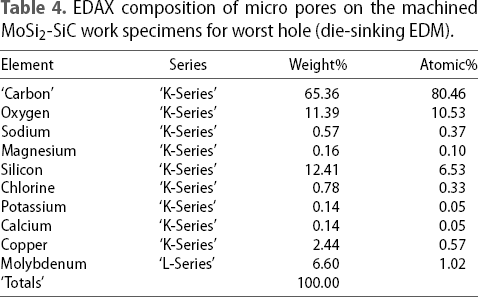
EDAX analysis of machined surface of MoSi2-SiC composite of worst hole (die-sinking EDM). EDAX composition of micro pores on the machined MoSi2-SiC work specimens for worst hole (die-sinking EDM).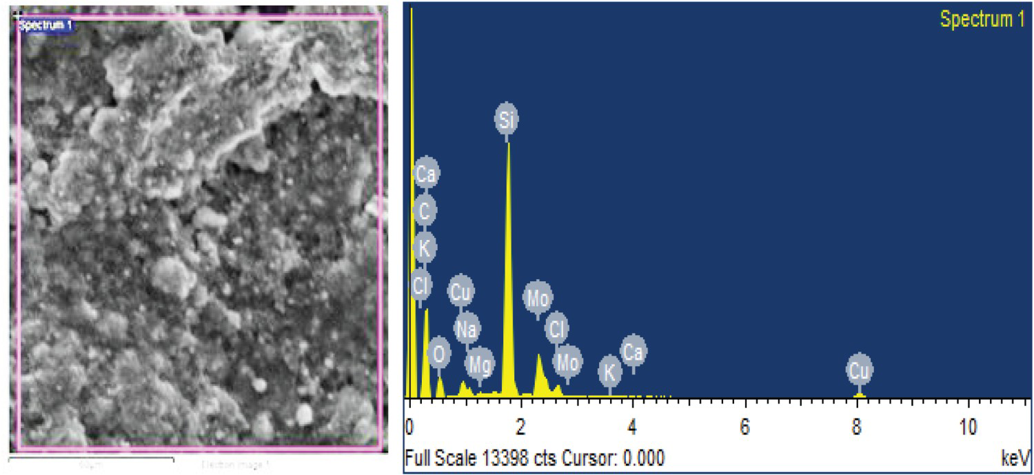
The EDAX data depicted in Figure 8 suggests that the machined exterior contains considerable amounts of carbon and silicon. The report verifies the surface's chemical make-up. Electrical discharge machining (EDM) involves melting and resolidifying the copper electrode, which has resulted in 2.44% copper being present. Electrode-position machining (EDM) is a metalworking technique that makes use of sparks generated by an electric current to carve and form the material. Some copper is included in the machined surface because the copper electrode is melted and then resolidified.
Micro structural analysis of MoSi2-SiC composite by rotary EDM
Micro structural analysis of optimum hole in MoSi2-SiC composite by rotary EDM
Figure 9(a) depicts the surface topography of a machined MoSi2-SiC composite. Rotary EDM's multi-response optimisation led to the most effective settings for the procedure. Because of the rotation and interruption of the arcs, the rotational EDM process leaves no evidence of small holes. The average diameter of the pores is around 7 µm. Shallow craters of an average size of 22 µm may be seen on the machined surface, further highlighting the terrain features. It is also important to note that the recast layer is far thinner than that produced by the die-sinking EDM method. In some cases, the resolidified particles may be swept away while the tool/arc turns. As seen in Figure 9(b), the thickness of the recast layer is not constant along its length. The MoSi2-SiC rotary EDMed surface has a more desirable overall character than the Si3N4-TiN composite. Another distinguishing trait is its high melting point of over 2000°C. The modified layer has a shallower depth than Si3N4-TiN, for reasons that are not fully understood. Figure 9(b) shows vertical sectional views of the machined exterior. According to observations, the altered layer is typically 30 µm thick. The recast layer's thickness is inconsistent because of the turbulence caused by the rotating electrode.
(a) Micro structural analysis and (b) cross-sectional area of MoSi2-SiC composite of an optimum hole (rotary EDM).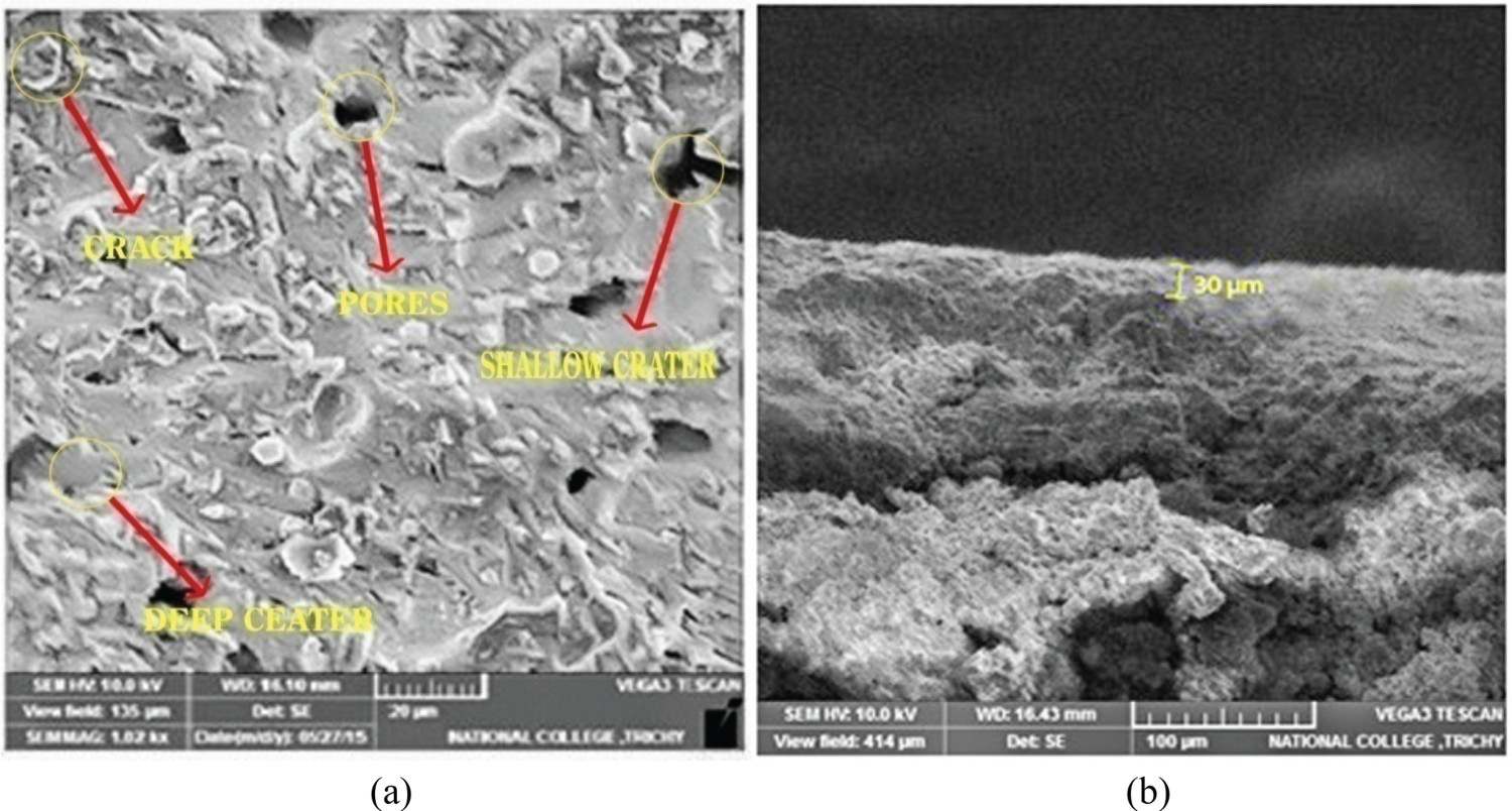
EDAX analysis of optimum hole in MoSi2-SiC composite by rotary EDM
Figure 10 shows how a shallow crater was machined into the surface of a MoSi2-SiC composite using rotary EDM and multi-objective optimisation. This figure incorporates the composition analysis that was accomplished with EDAX. When the pulse-off time and the servo voltage are both increased, the discharge frequency drops and less heat energy is created, resulting in less material removal. Tiny, shallow craters emerge on the cut surface as a result. Further contributing to the production of shallow craters is the fact that, as the wire feed rate is increased, the amount of time the wire spends in contact with the workpiece reduces. Table 5 displays the results of an EDAX calculation for this shallow crater surface flaw.
EDAX analysis on the machined surface of MoSi2-SiC composite of an optimum hole (rotary EDM). EDAX analysis of the machined work specimens of optimum hole (rotary EDM).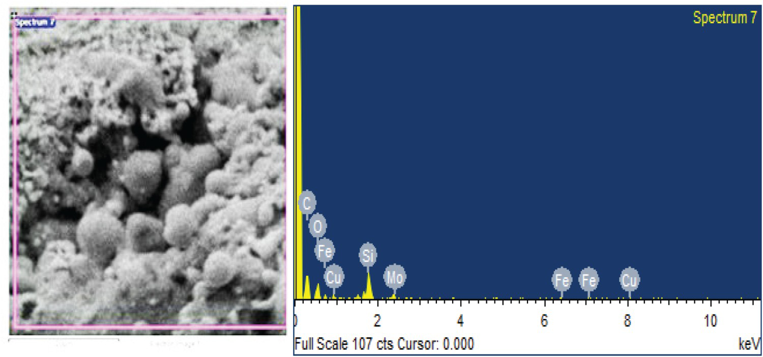
According to the EDAX report depicted in Figure 10, the lower porosity of the machined exterior is the result of the breakdown of MoSi2 and the production of oxygen. These findings corroborate the presence of light gases like oxygen and nitrogen, which make up around a quarter of the total mass. De-ionised water's potential to affect corrosion and surface deterioration during machining is discussed. Even while de-ionised water is less corrosive than regular tap water, it still requires careful management in metal manufacturing operations to prevent surface damage.
Micro structural analysis of best hole of MoSi2-SiC composite by rotary EDM
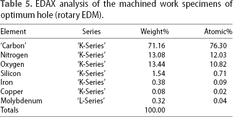
Figure 11(a) displays the findings of a topographical and cross-sectional study of the MoSi2-SiC composite following machining with optimised EDM settings for the formation of perfect holes. In general, the white layer and micro cracking on highly thermally conductive metals will be thinner and less extensive than on less conductive materials. Since highly conductive materials dissipate energy more uniformly across their surfaces. The topography reveals that there are some un melted spherical particles on the surface, as well as craters and occasional holes that are on average 3 mµ in size. Compared to before, there are now more pores present, and closer inspection of the topography reveals craters 12 µm across.
(a) Micro structural analysis and (b) cross-sectional area of MoSi2-SiC composite of best hole (rotary EDM).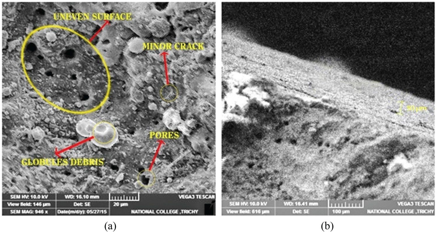
Figure 11(b) displays the typical depth of the recast layer to be 50 µm. When the optimum machining parameters were employed, it was discovered that the re-melted layer had a much greater depth than the recast layer, suggesting that considerable alterations had been made to the subsurface of the workpiece.
EDAX analysis of best hole of MoSi2-SiC composites by rotary EDM
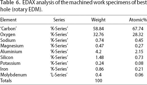
In Figure 11, EDAX composition analysis of globules on the machined surface of MoSi2-SiC composite during rotary EDM for best hole creation is depicted. According to Table 6's EDAX analysis, the globules formed because of surface tension in the molten metal. Figure 12.
EDAX analysis of machined surface of MoSi2-SiC composite of best hole by rotary EDM. EDAX analysis of the machined work specimens of best hole (rotary EDM).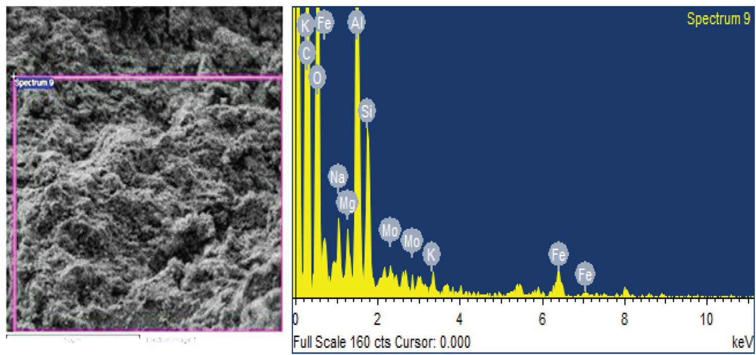
Micro structural analysis of worst hole in MoSi2-SiC composite by rotary EDM
After being machined with the Rotary EDM process that resulted in the worst hole, the microstructure of the MoSi2-SiC composite is shown in Figure 13(a). Large craters and numerous un melted spherical particles on the machined surface are indicative of the existence of poor conductivity phases that are difficult to remove. Moreover, the 2A current plays a role in keeping these un melted/resolidified globular particles on the machined surface. The crater left behind by the EDM process's electrical arc between the conductor and work material is also evident. The average diameter of the craters in the landscape is 9.31 µm.
Machined (a) Micro structural analysis and (b) cross-sectional view of MoSi2-SiC composite of worst hole (rotary EDM).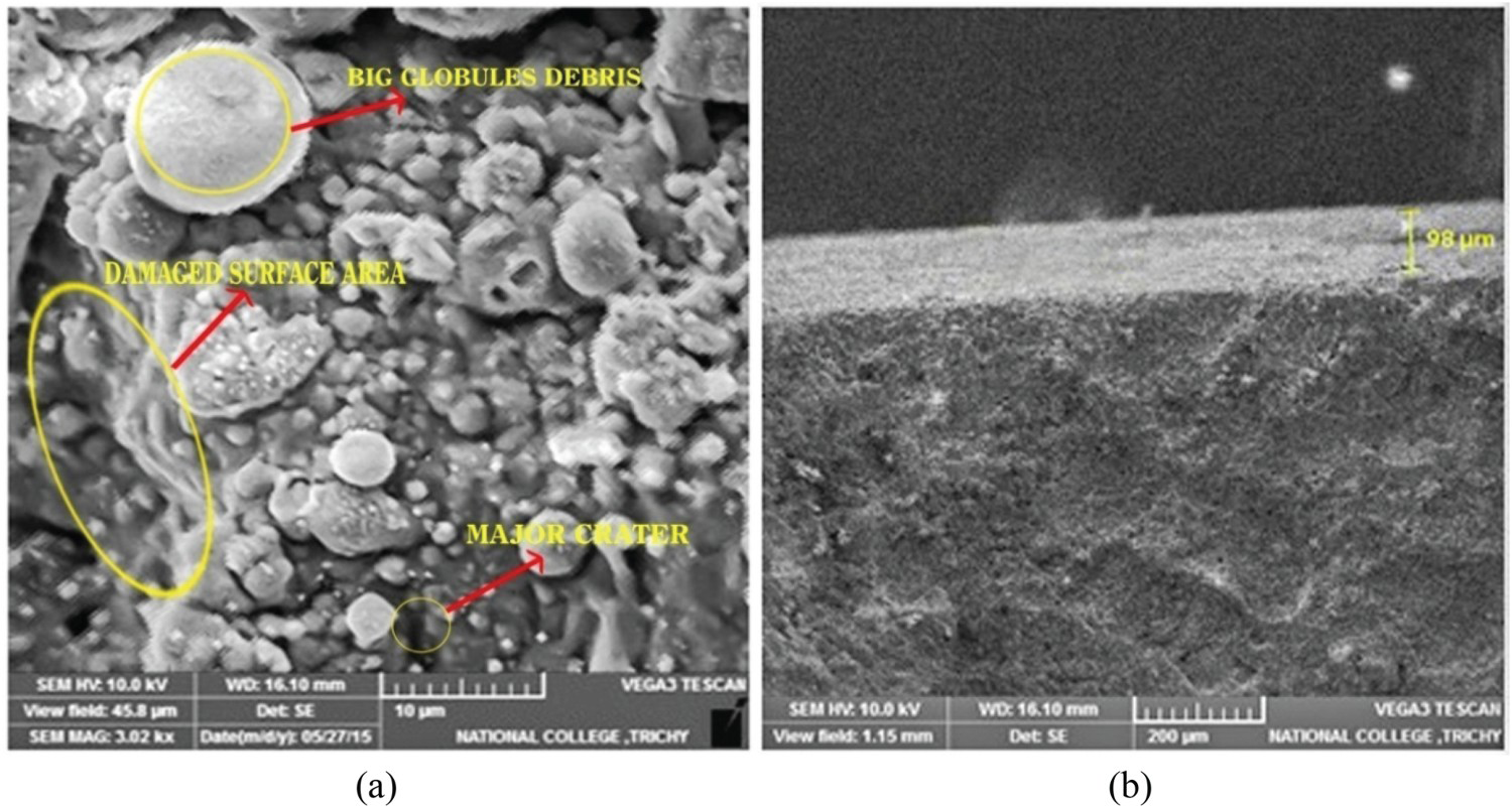
Recast layer generated during EDM process is shown in Figure 13(b), with an average depth of 98 µm. Changes to the subsurface of the workpiece are revealed by the altered deposit left behind after electrical discharge machining.
EDAX analysis of worst hole in MoSi2-SiC composite by rotary EDM
In the case of the rough surface of the MoSi2-SiC composite that was machined using rotary EDM, the EDAX study showed discrepancies in thermal energy that led to surface degradation.
EDAX analysis of worst hole in MoSi2-SiC composite by rotary EDM.

The optimisation of the EDM process is an important step in ensuring the quality of the machined parts. By using EDAX analysis and other analytical tools, it is possible to optimise the EDM process to achieve the best hole quality and minimise surface imperfections.
The EDAX analysis of this surface, which is depicted in Figure 14, confirms that silicon and carbon are present as the surface's primary components. The copper conductor's melting and resolidification during the EDM process is responsible for the presence of 11.13% of copper.
EDAX investigation of MoSi2-SiC composite for worst hole by rotary EDM.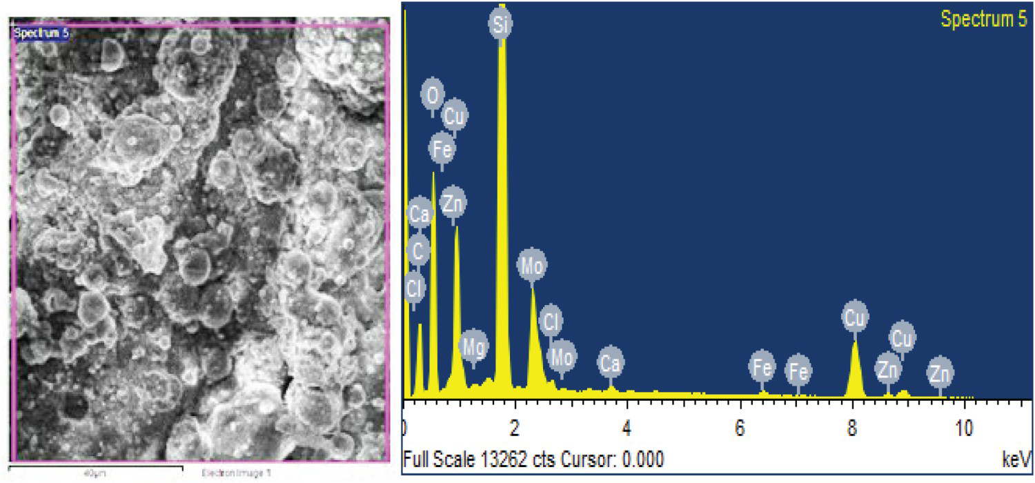
Measurement of the average surface roughness
The accuracy of the surface roughness test equipment, model SE1200, designed by Japan's KHOSACA Laboratory Ltd., and was 5.5 percentage points per metre (Figures 15 and 16).
Surface Roughness tester machine. Video measuring machine (VMM).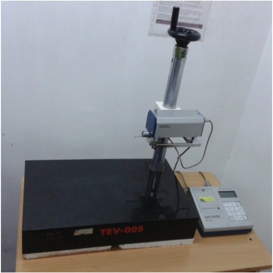
Calculation of taper
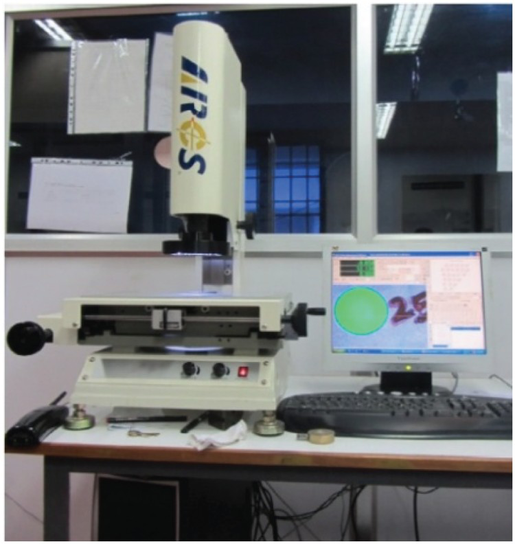
Precision metrology, such as the method depicted in Figures 17(a,b), includes the use of very exact measuring instruments and methods to precisely quantify an object's physical properties. Here, the top and bottom diameters of a drilled hole are measured to an accuracy of 3 microns using the video measuring device in conjunction with the ARCS software.
VMM pictures of holes (a) top view (b) bottom view.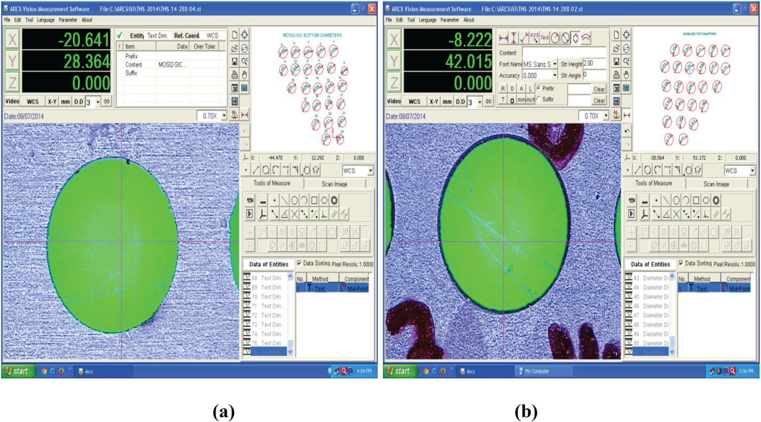
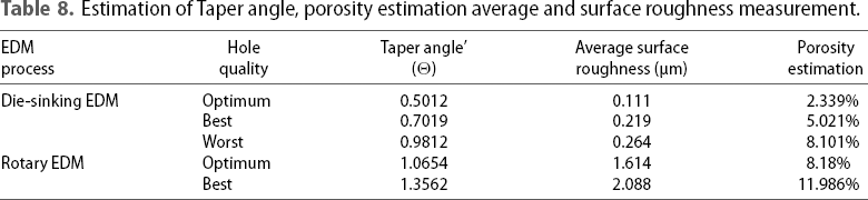
Estimation of Taper angle, porosity estimation average and surface roughness measurement.
In precise metrology, it is standard practise to utilise a Video Measuring Machine (VMM) to measure the diameter of a hole from both the top and bottom surfaces. Measurements of the hole's diameters taken with the VMM may be repeated with great precision and used to determine the hole's taper.
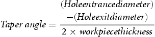
Taper is determined by measuring the angular difference between the hole's top and bottom diameters and expressing it as a degree value. For this, we use Equation (1), a mathematical formula that describes the relationship between the hole's diameter and its angular location [38].
Porosity estimation
An essential part of quality control for EDM oil dielectric medium, porosity assessment can reveal hidden flaws that might compromise the product's functionality if left unchecked. Engineers and technicians may make better judgements regarding the parameters, materials, and other aspects that affect the quality of the EDM process by keeping an eye on the porosity of the medium. Electrical discharge machining (EDM) procedures frequently run into trouble due to the pores in the EDM oil dielectric medium, which can have a major effect on the quality and performance of the end product. Supersaturated gas, often hydrogen, precipitates out of the molten pool and causes pores to develop throughout the EDM process. As a substance changes from a liquid to a solid state, pores occur because hydrogen is less soluble in the molten material.
SEM (Scanning Electron Microscopy) images of the best, worst, and perfect holes were analysed in ImageJ software to determine the porosity of the EDM oil dielectric medium. The porosity of the material may be estimated with the help of Image-J, which can count the number of pores in the images. Porosity estimate results, including the number of pores in the best hole, worst hole, and optimal hole, are summarised in Table 9. The related SEM images are shown in Figure 18; they may be used for a visual inspection of the pores and assessment of their size and distribution.
Micro structural analysis for estimating the porosity by using ImageJ software. Estimation of porosity by ImageJ software.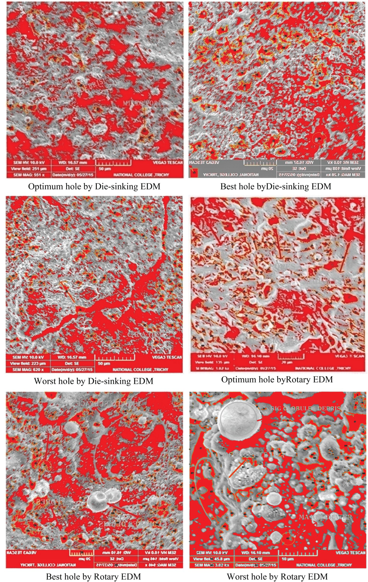
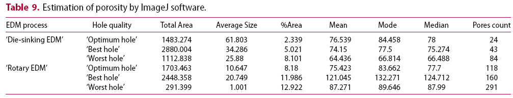
The area fraction yield for the porosity was calculated by doing a thorough analysis of the SEM (Scanning Electron Microscopy) images using Image-J software. The programme was utilised for calculating the fraction yield of porosity and counting the number of pores seen in SEM pictures.
The area fraction yield for the porosity for the best, worst, and optimum holes in both die-sinking EDM and rotary EDM are summarised in Table 9. According to the study's findings, the area fraction yield for porosity is between 8.18% and 12.922% in rotary EDM, but only between 2.339% and 8.101% in die-sinking EDM.
Deionised water was shown to be an effective dielectric fluid for rotational EDM, with the results indicating that the dielectric pore density increased with surface area for this process. The rapid cooling of the liquid in deionised water is responsible for this occurrence, since it inhibits the creation of bigger pores. After replacing EDM oil with deionised water, the number of external holes on the machined surface increased because of hydrogen and water vapour, the two primary sources of pores in deionised water.
The study's results can be utilised to optimise the EDM procedure and reduce pore growth on the finished product. When the process parameters are optimised and the right dielectric fluid is used, it is feasible to manufacture high-quality machined components with low porosity.
Conclusions
The study investigates various aspects such as electrode erosion rate, surface features, surface profile characteristics, and material erosion rate. The identification of features on the machined surface is performed through optical inspection, cross-sectional analysis, and energy-dispersive X-ray analysis.
The examination of machined surfaces of ceramic composites using Rotary EDM and Die Sinking EDM yielded the following concise conclusions:
Rotary EDM machining of MoSi2-SiC composite generates a significant amount of gas due to oxidation and decay of MoSi2. This gas production was confirmed by EDAX analysis, which attributed it to the use of de-ionised water as a dielectric. Rotary EDM process produces a thinner and less uniform recast layer compared to Die Sinking EDM. The rotating motion of the tool during EDM drilling sweeps aside resolidified particles, contributing to this difference. SEM analysis revealed that the primary erosion mechanism in both MoSi2-SiC EDM processes is melting and evaporation. Rotary EDM demonstrated the capability to produce superior surfaces with the lowest white layer thickness. Machined MoSi2-SiC can be utilised in the production of wear-resistant components such as ball bearings, shot blast nozzles, extrusion dies, and heat exchangers, addressing challenges such as wear, fatigue, and high temperatures. Both Die Sinking EDM and Rotary EDM remove material through high-temperature processes including evaporation, spalling, and micro-melting. SEM analysis identified surface defects in the recast layer, such as craters, debris droplets, micropores and globules.
Outcome of this research paper
Die-sinking EDM and rotary EDM produce the thinnest white layers with thicknesses of 92 and 30 µm, respectively. Additionally, rotary EDM significantly increases pore formation and ablation. The study also examines the porosity of the machined surface. Die-sinking EDM produces holes with porosities of 2.339% (best), 5.021% (worst), and 8.101% (optimum), while rotary EDM yields porosities of 8.18% (best), 11.986% (worst), and 12.922% (optimum). This indicates that die-sinking EDM generally produces lower porosity in the machined holes compared to rotary EDM. The study's results of porosity can be utilised to optimise the EDM procedure and reduce pore growth on the finished product. When the process parameters are optimised and the right dielectric fluid is used, it is feasible to manufacture high-quality machined components with low porosity. When rotary EDM was conducted using deionised water as the dielectric fluid, the quantity of external pores increased with the area. This phenomenon can be attributed to the cooling rate of deionised water, which hinders the formation of larger pores. The presence of hydrogen and water vapour in deionised water contributes to pore formation and when deionised water is used instead of EDM oil, the number of external pores on the machined surface increases. The EDAX results revealed that the machined surface, which displays the total number of holes, contained oxygen at a relatively high concentration of 37.74% by weight. Furthermore, this research investigates also that the surface erosion of the machined workpiece can be attributed to processes such as corrosion, melting/vaporisation, and thermal spalling.
Overall, the study provides a scientific analysis of the machining characteristics of MoSi2-SiC composites using different EDM techniques, highlighting the surface imperfections, recast layer thickness, porosity, and possible erosion mechanisms.
These conclusions provide enhanced scientific analysis of the machining characteristics and surface properties of MoSi2-SiC composites when subjected to different EDM processes.
Future research scope
The study of EDS elemental mapping and XRD spectrum analysis will be carried out for both Rotary and Die sinking electrical discharge machined materials of intermetallic ceramic composite intended for the purpose of its chemical synthesis.
Footnotes
Acknowledgements
The authors extend their appreciation to the Deputyship for Research & Innovation, Ministry of Education in Saudi Arabia for funding this research work through project number: IFP22UQU4310022DSR005
Disclosure statement
No potential conflict of interest was reported by the author(s).