
Abstract
Friction surface stirring (FSS) was employed to enhance the tribological properties of commercially pure Ti (CP-Ti). Applying FSS under the optimised process parameters (i.e. rotation and traverse speeds of 100 rpm and 8 mm/min, respectively) was found to increase the surface hardness of as-received CP-Ti from about 200–630 HV. The sliding wear resistance was therefore increased by 76, 76, and 85% under applied loads of 5, 10, and 20 N, respectively. The average friction coefficient (AFC) of CP-Ti also reduced considerably by the FSS. For instance, the AFC was reduced from 0.67 ± 0.07 and 1.04 ± 0.14 to about 0.33 ± 0.03 and 0.45 ± 0.04 at the applied loads of 5 and 20 N, respectively. The wear and friction mechanisms were also discussed.
Introduction
Commercially pure Ti is considered as a potent alternative to the commonly-used Ti-6Al-4 V alloy for biomedical applications owing to its low density, excellent corrosion resistance, inertness, and proper biocompatibility [1,2]. However, because of the low hardness and tensile strength, low fatigue strength, and poor tribological properties of CP-Ti, it is necessary to improve its mechanical and tribological properties through appropriate methods [2–4].
Severe plastic deformation techniques such as equal channel angular pressing (ECAP), multi-directional forging (MDF), accumulative roll bonding (ARB), high pressure torsion (HPT), and thermomechanical processes such as hot rolling (HR) and hot extrusion (HE) have the great potential to improve the (bulk) mechanical properties of materials [5]. There are also SPD processes such as ultrasonic peening, burnishing, ultrasonic nanocrystalline surface modification (UNSM), and surface mechanical attrition treatment (SMAT) [6,7] that only change the surface structure and properties of the material at their surface regions. However, these techniques usually require special/expensive equipment and have limitations regarding the shape and dimensions of the sample.
Friction stir processing (FSP) is an important SPD method capable of effective surface modification of alloys [8,9]. In FSP, a rotating non-consumable tool comprising of a pin and shoulder, is used to locally modify the microstructure and improve the surface mechanical/tribological properties. During the process, the frictional interaction between the rotating tool and the work piece increases the surface temperature whilst the rotation of the pin causes the surrounding material to flow. The FSP process significantly affects the microstructure through severe plastic deformation, material mixing and heat generation, and therefore leads to the effective refinement of grains/second phases, structural densification, and homogenisation [9,10].
The effects of FSP on the microstructure and mechanical properties [11–14], corrosion/electrochemical behaviour [14–17], and wear properties [17,18] of CP-Ti have been investigated. According to previous investigations, FSP can significantly improve the surface properties of CP-Ti by promoting the formation of ultrafine grains and increasing the density of dislocations and volume fraction of Widmanstätten structure [15,16,18–20]. Nonetheless, due to the high melting point (1668°C) and high flow stress of CP-Ti, the conventional FSP tools made of tool steel or WC are subjected to high temperatures and rather high loads [21]. Thus, severe damage/wear by hot adhesion and micro-constituents inter-diffusion mechanisms is inevitable [21,22]. Damaging the FSP tool not only deteriorates its performance but also may result in loss of surface quality and incorporation of inclusions into the workpiece [22]. Therefore, many efforts have been made to develop new potent FSP tool materials having high thermal durability/wear resistance and low sensitivity to abrupt temperature changes such as polycrystalline CBN, W-Re alloy, Mo-based alloy, and W-La [21,23]. However, despite their improved performance, these materials are generally expensive and fabricated through costly and tedious processes [22,23].
In view of these facts, a pinless tool design has been proposed to simplify the FSP process, decrease the exerted stresses on the tool, and reduce the processing time/cost. Zainelabdeen et al. [24] investigated the effect of friction surface stirring with a pinless tool on the microstructure and mechanical properties of 6061 Al alloy. They found that applying FSP significantly refined the microstructure and consequently improved the hardness and corrosion resistance of 6061 Al alloy. In another study, Arora et al. [25] investigated the effect of stationary FSP using a pinless tool on the microstructure and corrosion resistance of a Ni-Cr-5Al2O3 thermal barrier coating. According to their results, the effective microstructural refinement/homogenisation of the processed coatings resulted in a remarkable increase in its corrosion resistance of about 5 times. Singh et al. [26] studied the effect of FSP using a pinless WC tool on the microstructure and mechanical properties of SA210 Grade A1 boiler steel. They found that applying FSP refined the grain structure and improved the microhardness and tensile strength, substantially. The mechanical properties improvements have been attributed to the refinement of grains and the austenite to martensite and ferrite transformation.
Even though the performance of pinless FSP tools or in other words the influence of friction surface stirring on the microstructure refinement and properties enhancement of some alloys has been investigated, to our knowledge no previous work has dealt with the effect of FSP on the modification of CP-Ti using a pinless tool. Therefore, this study was undertaken to investigate the variations of the hardness and tribological properties of CP-Ti after FSP using a pinless WC tool.
Materials and methods
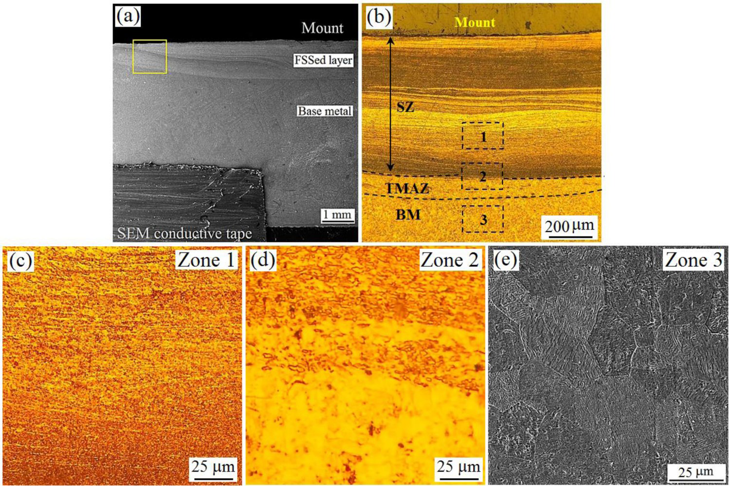
CP-Ti (Grade 2) sheet with the chemical composition shown in Table 1 was used in this study. Samples with dimensions of 250 × 200 × 6 mm were prepared from the as-received sheet using a wire cut machine. After cleaning the surface with abrasive paper SiC (Grit # 800) FSS was applied on the sample surface using a pinless WC-Co tool with a 16 mm diameter and 100 mm length (Figure 1). Single pass FSS was conducted at the different rotation speeds of 50, 100, 200, 400, and 600 rpm and sliding speeds of 8, 12, 25, and 50 mm/min. The FSSed samples are indicated by a two-part number system as XXX-XX. The first part refers to the rotational speed (rpm) and the second part (after dash) denotes the sliding speed (mm/min). The setup of the process is shown in Figure 1.
Setup of the FSS using WC-Co pinless tool. Chemical composition of CP-Ti, wt. %.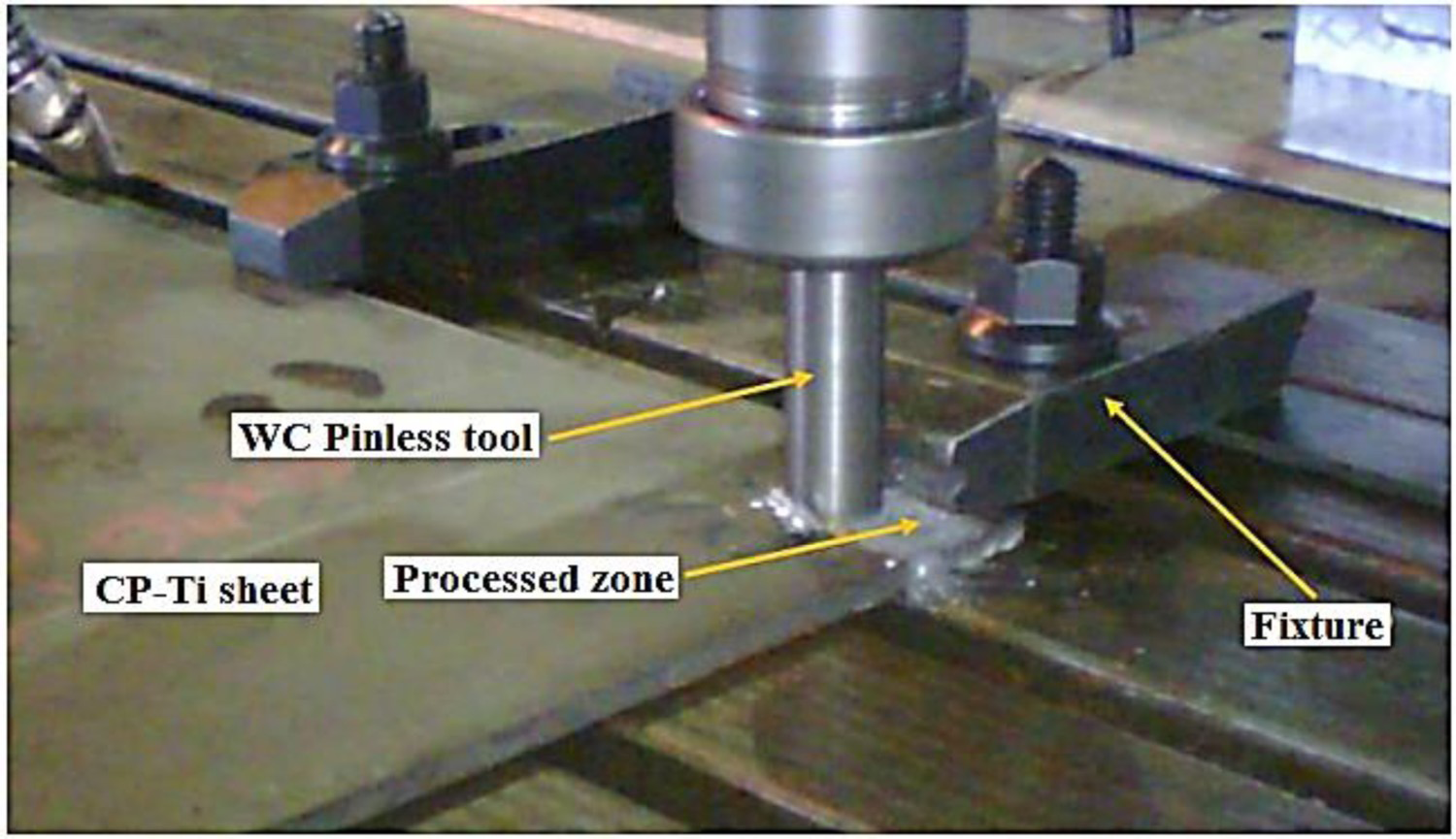
The hardness of the samples was determined according to ASTM E384 standard using a microhardness tester (Kala Sanat-Azma) under the applied load of 500 gf and dwelling time of 15 s. The average of 10 indentation measurements at different locations on the stirred zone was reported as the final hardness. The pin-on-disk room temperature sliding wear tests were carried out according to ASTM G99 at the sliding speed of 0.13 m/s, different applied loads of 5, 10, and 20 N, and at a distance of 1000 m. The rectangular pins with dimensions of 5 × 5 × 10 mm were used against an alumina disk counterface. Before each test, the samples were ultrasonically cleaned in acetone.
The surface preparation of metallography samples was performed according to the standard metallographic procedures. The surfaces were chemically etched using a solution containing 5 mL H2O2 (30%), 2 mL HF, and 100 mL distilled H2O for 20 s to reveal the microstructure/grain structure. The microstructure of the samples was examined by a MIRA3 TESCAN scanning electron microscope (SEM) equipped with an EDS detector for elemental analysis of the samples. X-ray diffraction test was performed with a copper cathode lamp with Kα1 rays at a wavelength of 1.54 Angstroms, with a scanning angle range of 2θ = 0.02° and a scanning time of 0.8 s.
Results and discussion
Effect of FSS on surface hardness of CP-Ti
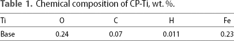
The effect of process parameters (rotation and traverse speed) on the Vickers hardness of FSSed samples at a depth of about 35 ± 5 µm below the surface is shown in Figure 2(a). As seen, applying FSS can significantly enhance the surface hardness of CP-Ti. For instance, under the optimised parameters (i.e. rotation speed of 100 rpm and traverse speed of 8 mm/min) the hardness of as-received CP-Ti has increased by more than 210% (i.e. from 198 ± 6 to 631 ± 11 HV).
(a) Effect of FSS parameters on the hardness of CP-Ti (at a depth of about 35 µm beneath the processed surface) and (b) hardness profiles of selected FSSed samples beneath their processed surface.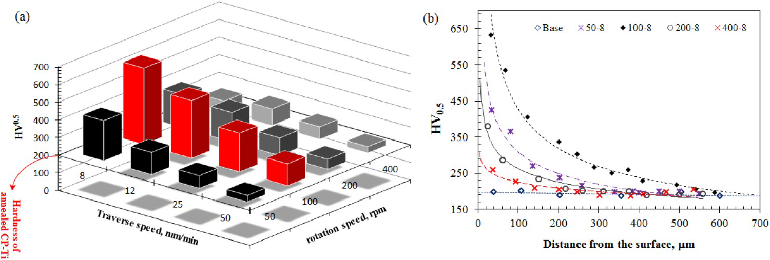
The FESEM and OM micrographs showing the cross-sectional view of the processed zone of FSSed CP-Ti sample comprising of stir zone (SZ), thermo-mechanically affected zone (TMAZ), and unaffected base metal (BM) are shown in Figure 3(a, b), respectively. The higher magnification micrographs showing the detailed microstructure of aforementioned zones in Figure 3(b) are also illustrated in Figure 3(c–e). As seen, applying FSS transformed the coarse (14.7 ± 3.6 µm) original grain of the BM (Figure 3(e)) into ultrafine equiaxed grains in the severely deformed SZ layer (Figure 3(c)). Due to the severe plastic strains applied and high temperatures generated during the process (to be discussed later), the grain refinement can be correlated to the occurrence of dynamic recrystallisation phenomenon [9,10].
Therefore, according to the Hall-Petch relationship, the hardness improvement of FSSed CP-Ti samples can be partly attributed to the increased density of grain boundaries as strong obstacles to dislocation movement [27]. Similar results were also reported by various researchers. In their investigations on the effect of FSP on microstructure and wear behaviour of pure Ti, Vakili-Azghandi et al. [18] showed a substantial reduction in the grain size from more than about 50 µm to about 3 µm in the SZ of a 3-pass FSPed sample. It was claimed that this refinement resulted in the BM hardness growth from 173 HV to 269 HV (∼ 36%). The formation of ultrafine recrystallised grains in the SZ of FSWed pure Ti has been also reported by Mironov et al. [13]. Shamsipur et al. [28] also reported a 90% reduction in the grain size of Ti-SiC composites upon FSP (the final grain size was less than about 4 µm) which caused a hardness growth of about 88% from about 160 HV to about 300 HV.
In agreement with the previous studies [29,30], the second possible mechanism responsible for the hardening of FSSed CP-Ti is the dispersion hardening of ultra-hard TiN particles (2400-2800 HV [31]) as well as hard TiO2 particles (∼ 1400 HV) [32]. Indeed, due to the significant increase in the temperature of the SZ of FSSed sample (Figure 5(a)) TiN particles (Figure 4(a)) with the EDS analysis shown in Figure 4(b) are thought to be formed in situ as a result of inward diffusion and subsequent reaction of surrounding atmosphere nitrogen atoms with the SZ Ti atoms. It is worth noting that the EDS peaks of the N (∼379 eV) and the Ti (∼387 eV) overlap (Figure 4(b)) making it difficult to obtain a N map. Considering the high Ti affinity to react with oxygen, the in-situ formation of TiO2 particles is also likely as shown in the EDS mapping of the surface layer of 100-8 sample (Figure 4(c–e)).
(a) SEM micrograph showing the presence of TiN particles in the upper layers of the SZ of 100-8 sample, (b) EDS analysis of TiN particles, SEM-EDS elemental mapping of the processed surface of 100-8 sample where (c) back scattered electron image, and the elemental mapping of (d) O and (e) Ti.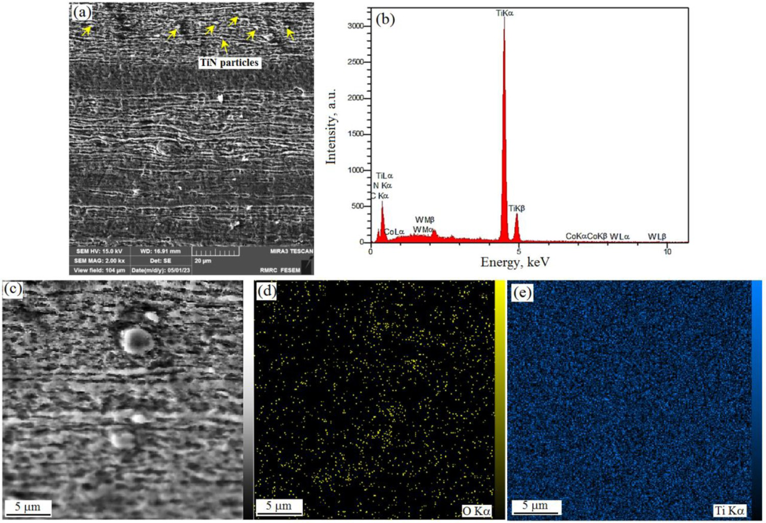
It is generally accepted that severe plastic deformation can markedly increase the dislocation density of the processed zone. The recrystallised grains are also thought by most to have few numbers of dislocations. However, based on the previous studies, in addition to dislocation networks along the sub-grain boundaries, some recrystallised grains contain a significant number of dislocations [33–35] which can enhance the hardness through the dislocation strengthening mechanism as the third possible hardness-improving mechanism.
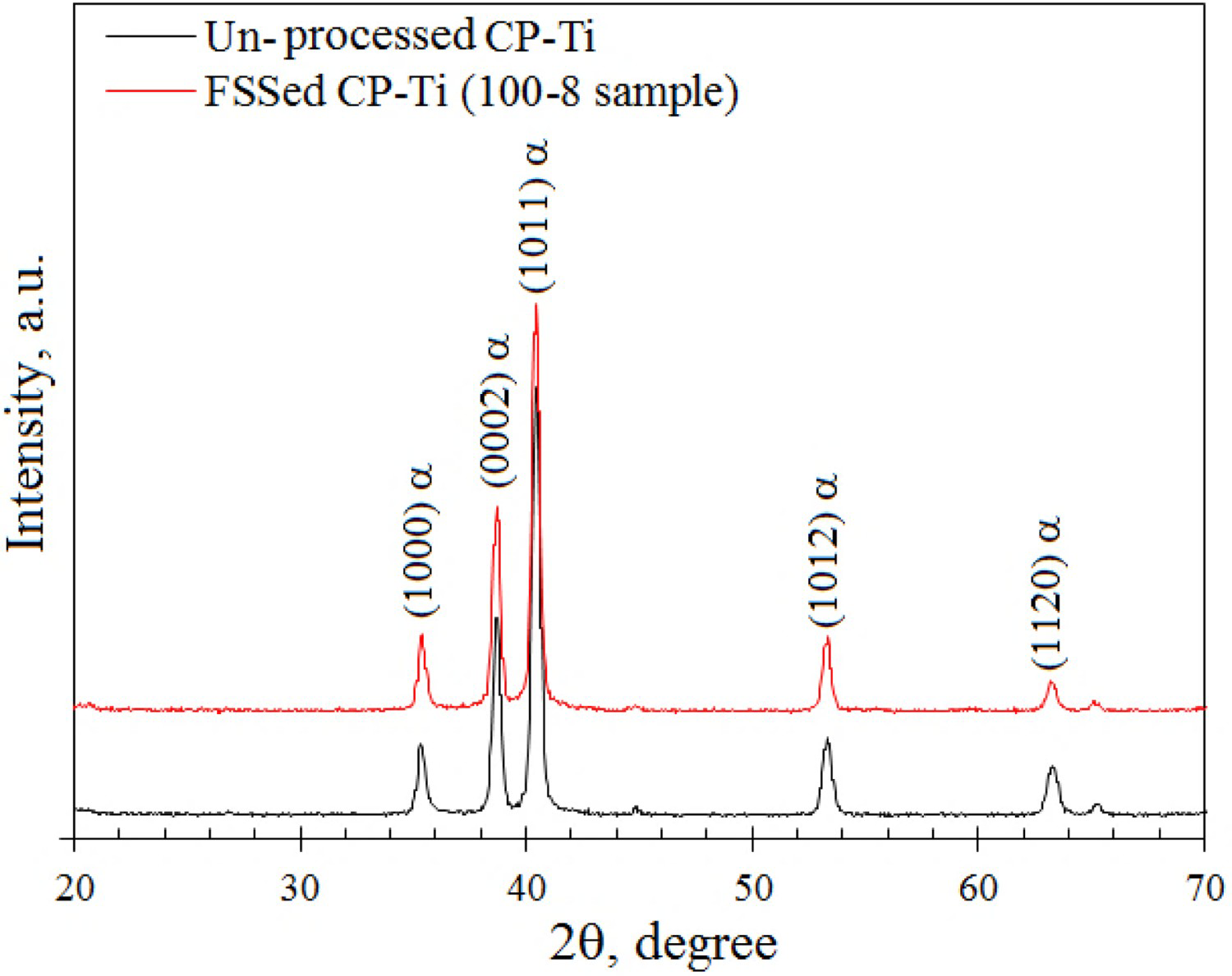
The effect of selected parameters on the maximum surface temperature of samples during the FSS is shown in Figure 5. As seen, under the optimised condition (Figure 5(a)) the tool interface has experienced a maximum surface temperature of about 720°C which is far lower than the allotropic α-phase/β-phase transformation of pure Ti (about 880°C [18]). Therefore, in accordance with previous studies [20,36] the formation of acicular α′-martensite through α-to-β phase transformation followed by rapid cooling of the β-phase is unlikely in the 100-8 FSSed sample as was confirmed by the SZ microstructure of the 100-8 FSSed sample in Figure 3(b,c). It is worth noting that the crystal structures of α-Ti and α′-martensite are identical and their lattice parameters are nearly the same [37]. Thus, the XRD analysis, although revealing the phases present in the microstructure of un-processed and FSSed processed CP-Ti samples, was unable to verify whether or not the α′-martensite has formed (Figure 6).
Infrared thermography images showing the effect of FSS on the maximum surface temperature at the tool interface of (a) 100-8, (b) 400-8, (c) 50-8, and (d) 50-50 samples. XRD patterns of un-processed CP-Ti and FSSed 100-8 CP-Ti.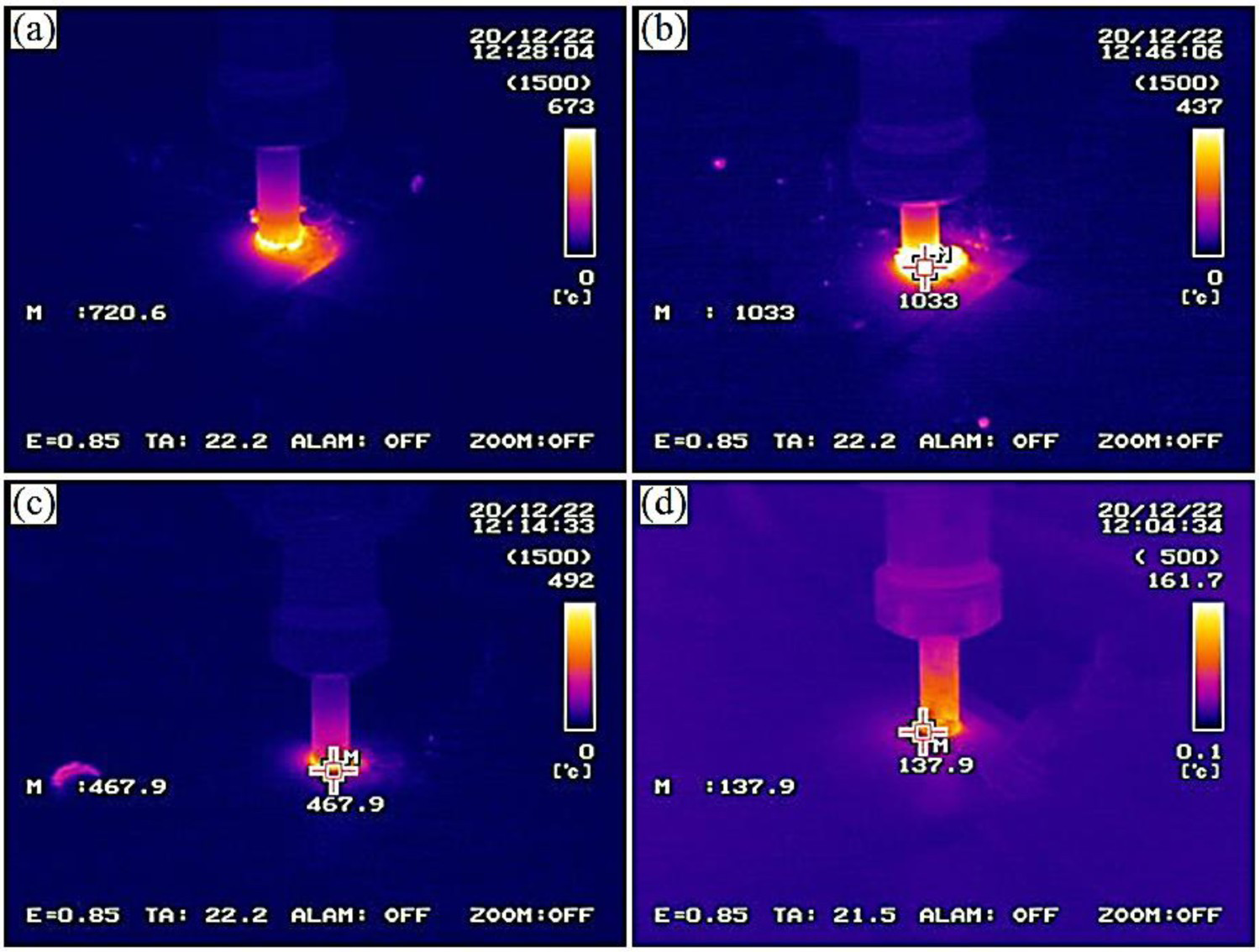
According to the following equation (Eq. 1) [38] and assuming other parameters are constant, any change in rotation and/or traverse speeds causes a change in the amount of heat input (Q) distributed in the stir zone:
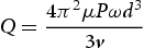
Therefore, FSS using non-optimised parameters not only changes the surface applied strains but also may change the heat input distribution in the SZ in such a way that worsens the material plastic behaviour. According to Figure 7, probably due to the insufficient heat input (low tool interface temperature) and in agreement with the previous studies [39,40], FSS under the lower-than-optimum rotation speeds or higher-than-optimum traverse speeds may cause defects such as pores, cracks, and kissing bonds in the SZ microstructure (Figure 7(a, b)). Due to the lack of material plasticity and/or inefficient mechanical intermixing of the base plates, the formation of these defects with adverse effects on the hardness of the processed zone (Figure 2) is likely.
OM micrographs showing the effect of improper heat input on formation of (a) kissing-bond and (b) porosity in 50-8 sample and (c) turbulent material flow in 400-8 sample.
Applying FSS under the higher-than-optimum rotation speeds/lower-than-optimum traverse speeds may substantially increase the heat input (maximum surface temperature) (Figure 7c). This accordingly promotes the turbulent flow of the material in the course of the process giving rise to insufficient shearing to material transport and a higher chance of defect reformation. The abrupt increase in the processed zone temperature can also encourage grain growth.
Effect of FSS on tribological properties
The variation of the wear rate and specific wear rate of the as-received CP-Ti and 100-8 FSSed samples against applied load is shown in Figure 8(a, b), respectively. As seen, under the applied loads of 5, 10, and 20 N the wear rate of FSSed sample is lower than that of the as-received CP-Ti by about 76, 76, and 86%, respectively. In addition, while the 100-8 sample showed a mild increasing trend in its wear rate against the applied load, a strong increasing trend is observed in the wear rate of the as-received CP-Ti sample against the applied load. Moreover, a transition from the mild to the more severe wear regime is observed in the wear behaviour of the as-received CP-Ti sample as the applied load exceeds 10 N (Figure 8(a, b)).
Variation (a) wear rate and (b) specific wear rate of the as-received CP-Ti and 100-8 FSSed Ti sample against applied load.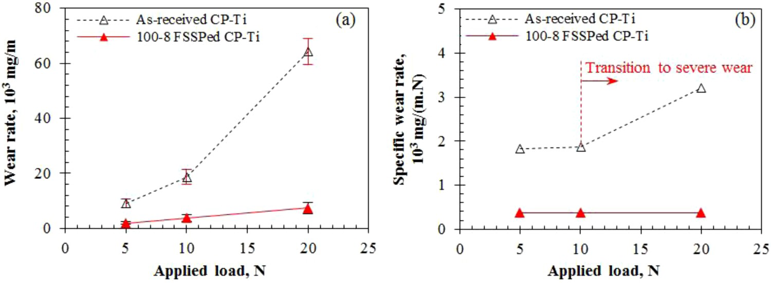
In order to investigate the FSS effect on the wear behaviour of CP-Ti and to explain the related wear mechanisms, the worn surfaces and wear debris were examined by SEM. Figure 9 shows the worn surface morphology of the as-received CP-Ti after 1000 m of wearing under the applied loads of 5 and 20 N. The EDS analysis of the worn surface is also presented in Table 2.
(a) SEM images showing the worn surface of the as-received CP-Ti after wearing under the applied loads of (a,b) 5 N and (c,d) 20 N. The sliding direction is shown by an arrow. EDS analysis of marked points in Figure 9.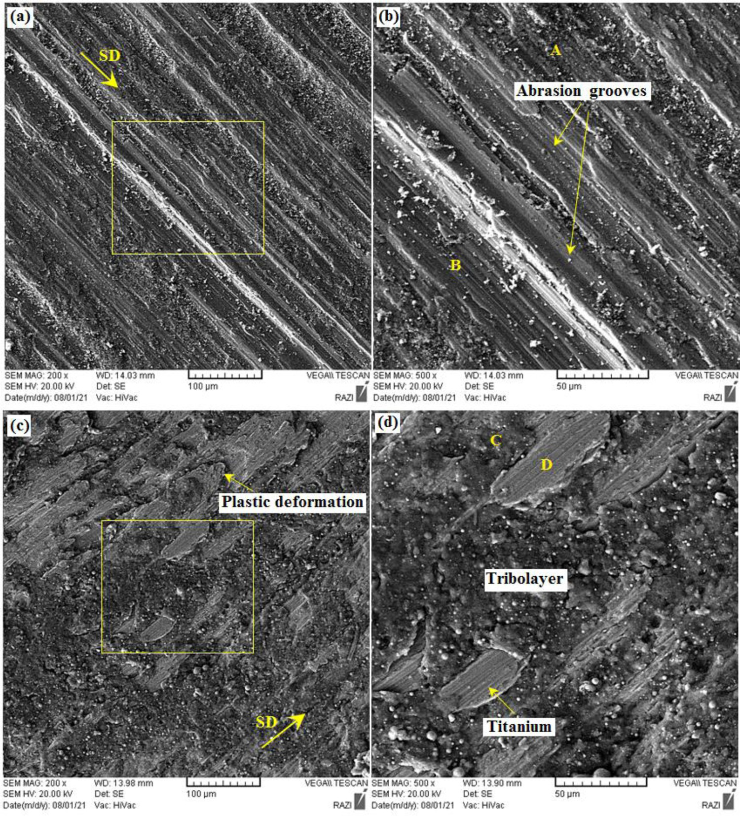
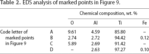
According to Figure 9a, its enlarged view (Figure 9b), and EDS analyses presented in Table 2, at the applied load of 5 N the worn surface of the as-received Ti was covered by an oxide-rich tribolayer which has experienced considerable delamination and abrasion as the dominant wear mechanisms. A tribolayer is formed when solid particles generated during the wear of both surfaces are compressed and mixed chemically and mechanically [41]. It is believed that the tribolayer greatly reduces the friction and adhesion between the contacting surfaces due to its composition (high oxide content) and porous character. This is owing to the fact that the tribolayer lowers the possibility of direct contact and cold welding between the surface asperities [42] However, the unprocessed Ti substrate, with low hardness, deforms plastically and renders the tribolayer unstable under high sliding-induced strains and intense frictional heat. The partial removal of the tribolayer from the worn surface is evident in Figure 9(a) where some areas, such as point B, exhibit similar composition to CP-Ti substrate (Table 2). According to Figure 10(a), under the applied load of 5 N, wear debris is composed of relatively small-sized equiaxed and relatively large plate-like particles.
SEM images showing the wear debris morphology of as-received CP-Ti under the applied loads of (a) 5 N, and (b) 20 N.
After wearing under the high applied load of 20 N the un-processed Ti sample has experienced severe surface damage (Figure 9(c, d)). As a rule of thumb, the tribolayer stability is significantly influenced by its substrate mechanical properties namely hardness and toughness [43]. Therefore, the formation of large metallic patches free of protective tribolayer on the worn surface can be regarded as an indication of extensive tribolayer delamination that is seemingly occurred as a result of the increased temperature (substrate softening) and lack of sufficient support from the tribolayer.
According to Figure 11(a), the substantial substrate plastic deformation of the un-processed Ti sample after wearing under the applied load of 20 N has resulted in the formation of large extruded upset visible at the edges of the pin. Therefore, in agreement with the previous studies [18,44,45] severe tribolayer delamination and plastic deformation can be considered as the main wear mechanisms. This is while the occurrence of wear debris between the sliding surfaces can also promote the abrasive wear mechanism. The generation of high-volume fractions of large plate-like wear debris comprising oxide-rich and metallic particles during wear of the as-received CP-Ti (Figure 10(b)) also indicates the occurrence of severe delamination and wear.
SEM images showing the substrate plastic deformation of CP-Ti after wearing under the applied load of 20 N (a) as-received Ti and (b) 100-8 FSSed samples.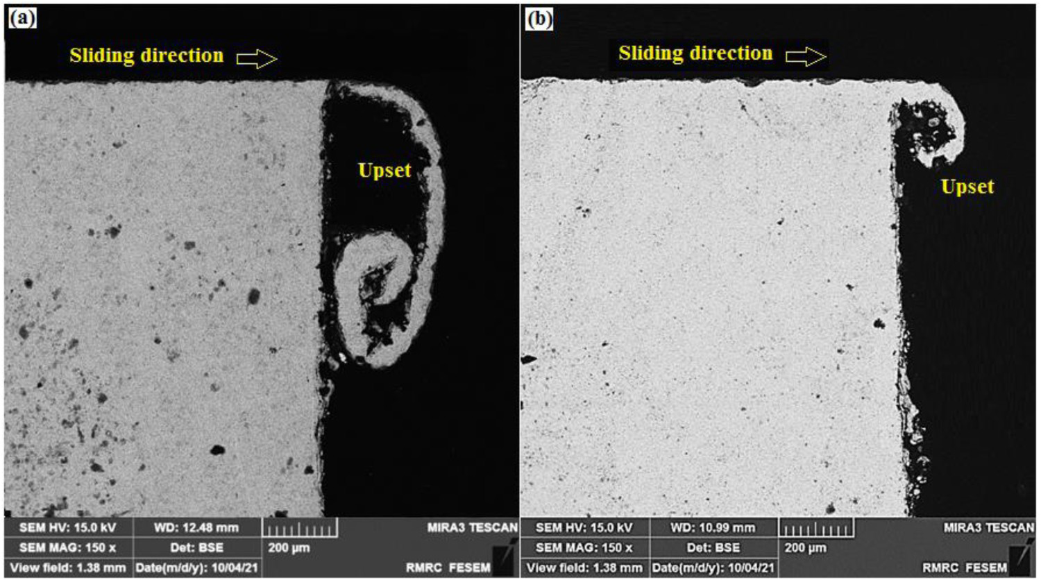
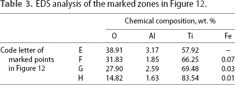
The morphology of the worn surface of the 100-8 sample after sliding under the applied loads of 5 and 20 N is shown in Figure 12(a, b), respectively. As can be seen, irrespective of the applied load and compared to the as-received unprocessed Ti sample (Figure 9), the worn surface of FSSed samples was covered by a stable and compact tribolayer (with the chemical analysis presented in Table 3) with small pits/craters and shallow abrasion grooves in the sliding direction. The enhanced hardness of the substrate of the 100-8 sample compared to the base sample (about 70% higher) accounts for the substantial decrease in the size of the pits/craters on the worn surface and an increase in the wear resistance (Figure 8). Increasing the substrate hardness lowers the amplitude/depth of the friction-induced surface plastic deformation (Figure 11(b)) and enhances its ability to support the tribolayer.
SEM images showing the worn surface of 100-8 FSSed sample after wearing under the applied loads of (a,b) 5 N and (c,d) 20 N. The sliding direction is shown by an arrow. EDS analysis of the marked zones in Figure 12.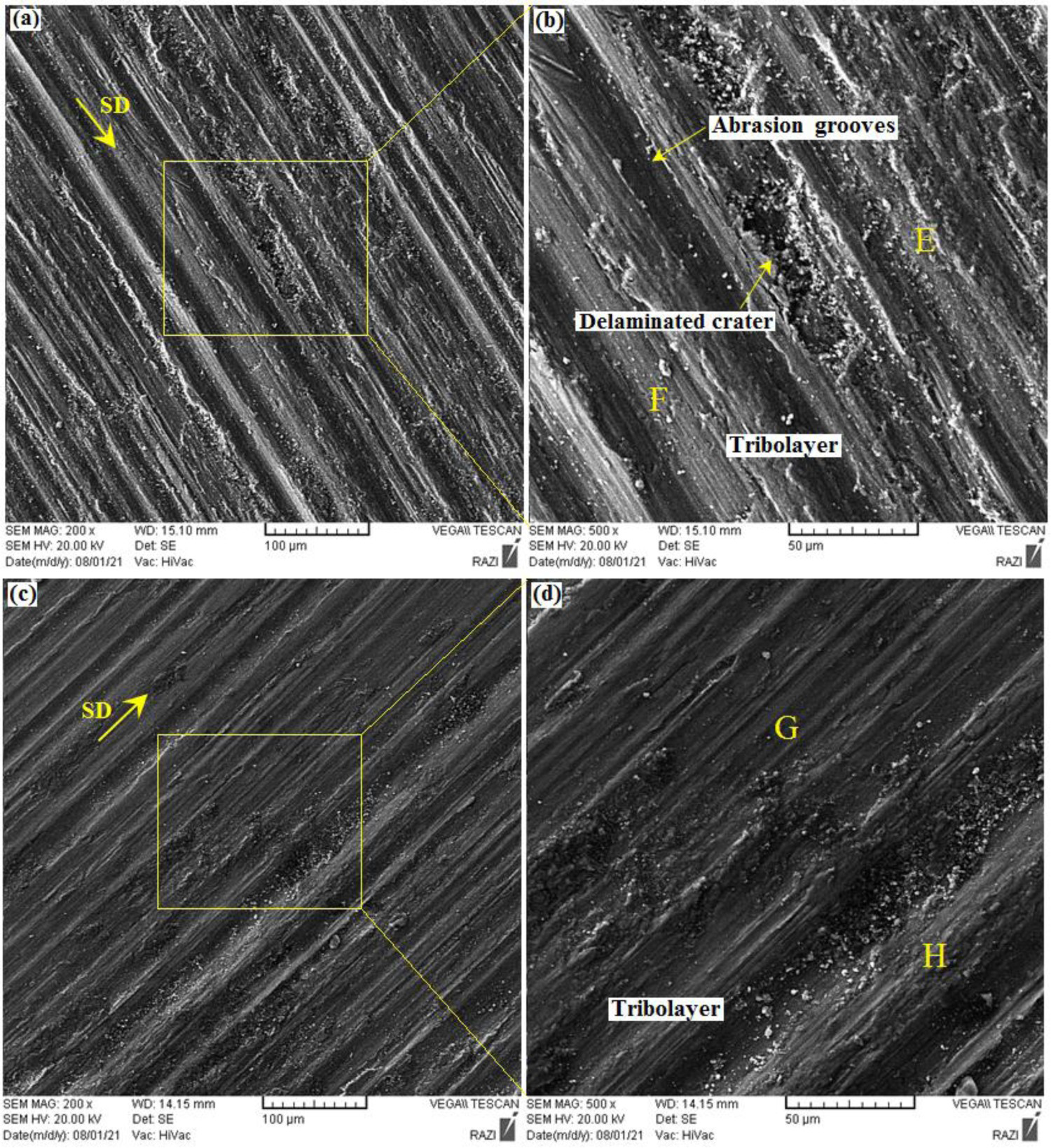
The parallel grooves formed on the worn surface of the 100-8 sample were also originated from the three-body abrasion by the hard debris involved between sliding surfaces. The size distribution and morphology of the wear debris of 100-8 sample after sliding under the applied pressure of 5 and 20 N are shown in Figure 13(a, b), respectively. As seen, in agreement with the wear results (Figure 8) and the morphology of the worn surface (Figure 12), the wear debris was mainly composed of fine and ultrafine equiaxed and small-sized plate-like particles. Therefore, mild tribolayer delamination/abrasion can be considered as the dominant wear mechanism in the 100-8 sample.
SEM images showing the wear debris morphology of 100-8 FSSed sample after wearing under the applied loads of (a) 5 N, and (b) 20 N.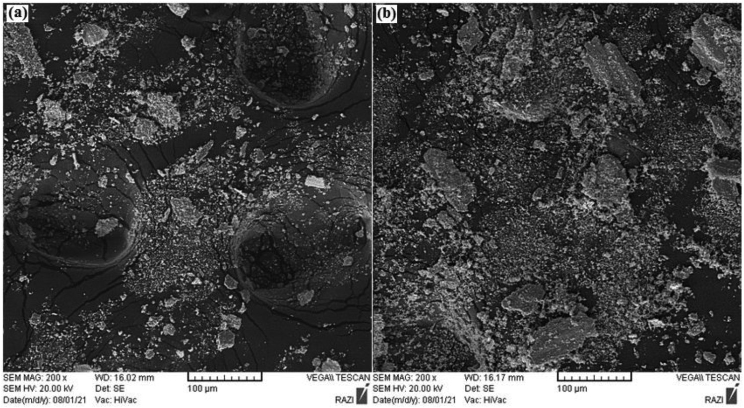
The variation of friction coefficient with the sliding distance of the as-received and 100-8 FSSed samples at the applied loads of 5 and 20 N is illustrated in Figure 14(a, b), respectively. As seen, following the running-in period whose occurrence can be explained by increasing the real contact area, generation, actions, and ejection of entrapped wear debris between sliding surfaces (three-body abrasion), and work hardening of surfaces [46–48], a steady-state trend is attained in the friction behaviour of samples. During the steady-state period, FSS has significantly reduced both the average value and fluctuation range of the friction coefficient (Figure 14). For instance, under the applied loads of 5 and 20 N, the AFC values of the 100-8 sample (0.33 ± 0.03 and 0.45 ± 0.04) are lower than those of as-received CP-Ti (0.67 ± 0.07 and 1.04 ± 0.14) by about 50% and 57%, respectively.
Friction coefficient diagrams of (a) as-received and (b) 100-8 samples under the applied loads of 5 and 20 N.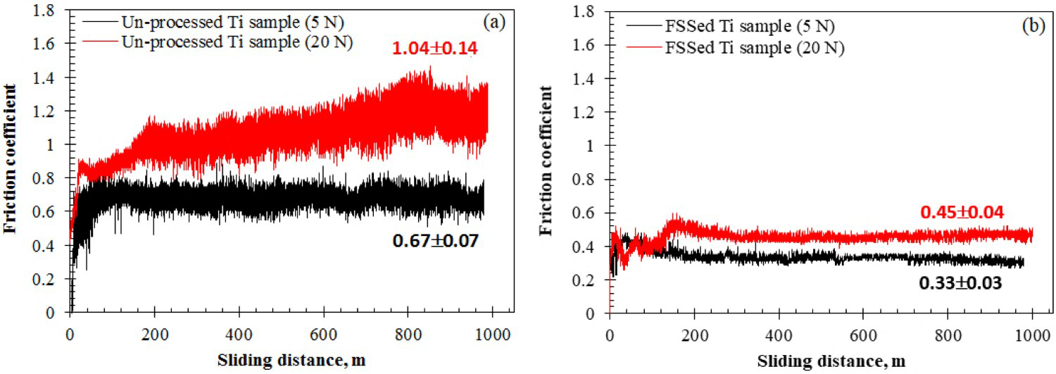
The sliding friction coefficient can be expressed as the ratio of the interfacial shear strength to the hardness of the softer component [49]. Therefore, in accordance with the wear results (Figure 8) and worn surface morphologies (Figures 9 and 12), the improved friction behaviour of FSSed samples can be explained by their higher surface hardness (Figure 2) and the formation of a dense compacted tribolayer on their worn surfaces. Indeed, the oxide tribolayer, on the one hand, reduces the possibility of adhesion between sliding surfaces (and therefore, the abrasion component of the friction coefficient) and on the other hand, reduces the pin-counterface interfacial shear strength.
The formation of a protective tribolayer on the worn surface also improves the friction behaviour under higher applied loads. According to Figure14(a), increasing the applied load substantially increases the friction coefficient/friction coefficient fluctuations of the as-received Ti sample, probably due to increasing the frictional interaction and overheating of the mating surfaces. However, its negative impact on the friction coefficient of the FSSed 100-8 Ti sample is much less (Figure 14b).
Conclusion
The effect of friction surface stirring using a pinless WC tool was investigated on tribological properties of CP-Ti. The process was conducted under different rotation speeds of 50, 100, 200, 400, and 600 rpm and sliding speeds of 8, 12, 25, and 50 mm/min. The following results can be drawn:
Applying FSS significantly enhanced the surface hardness of CP-Ti. Under the optimised parameters (i.e. rotation speed of 100 rpm and traverse speed of 8 mm/min) the hardness of as-received CP-Ti increased by about 220% (from 198 ± 6 to 631 ± 11 HV). This improvement was mainly attributed to the increased density of grain boundaries as strong obstacles to dislocation movement and dispersion hardening of ultra-hard TiN particles in α-Ti matrix of samples. Applying FSS also substantially improves the wear resistance of CP-Ti. According to the wear results, under the applied loads of 5, 10, and 20 N the wear rate of 100-8 FSSed sample was lower than that of the as-received CP-Ti by about 76, 76, and 85%, respectively. The wear mechanism changed from severe adhesion/plastic deformation in as-received Ti to relatively mild delamination/abrasion of the tribolayer in FSSed Ti. FSS also significantly reduced both the average value and fluctuation range of friction coefficient. According to the friction data, under the applied loads of 5 and 20 N, the AFC values of 100-8 FSSed sample (0.33 ± 0.03 and 0.45 ± 0.04) were lower than those of as-received CP-Ti (0.67 ± 0.07 and 1.04 ± 0.14) by about 50% and 57%, respectively.
Footnotes
Disclosure statement
No potential conflict of interest was reported by the authors.