
Abstract
To improve the load-bearing capacity, hardness and adhesion strength of the TiN coatings, the in situ plasma nitriding-PVD duplex treatment was applied. The substrate was pretreated by bombardment with highly ionised Ar+, functioned as an ‘ionic abrasive blasting’ for better adhesion. The microstructure and properties of the duplex-treated TiN coatings were characterized and analysed. The results show that the thickness of the plasma nitriding zone and the nanocrystalline TiN coating are about 50 μm and 4.1 μm, respectively. Owing to the ion etch-cleaning process prior to the duplex treatment and the γ′-Fe4N phase formed in the compound layer, the adhesion strength level of the TiN coating reaches HF1. The indentation profile analysis reveals that the nitriding process effectively increases the load-bearing capacity. Meanwhile, the instinct hardness reaches 2166HV0.05 and the sufficiently low wear rate coefficient is 8.30 × 10⁻⁹ mm−3 Nm−1. Moreover, the duplex-treated TiN coating has significantly improved the corrosion resistance.
Introduction
TiN coatings have been widely used as protective coatings on tools for numerous machining and forming applications such as cutting inserts, mechanical components or moulds due to their outstanding physical properties, such as ultrahigh hardness, improved tribological properties as well as chemical and thermodynamic stability [1,2]. However, the performances of hard and brittle coatings on compliant substrate materials are influenced by in-service loading conditions and residual stresses [3-5]. The TiN coating-substrate system, limited by the low bearing capacity, insufficient plastic deformation and adhesion strength, may easily suffer from a failure mechanism of ‘eggshell-like failure’ [6]. To solve the problems, an integrated plasma nitriding and PVD duplex treatment technology is emerging in recent years [7-11].
In the duplex treatment, nitrogen molecular gas is ionised in a glow discharge plasma during plasma nitriding process, to produce energetic nitrogen ions that enhance substrate diffusion and produce a modified layer with high nitrogen concentration [10,12]. The input of nitrogen atoms into the surface leads to the formation of compressive stresses in the nitrided region that increases the load-bearing capacity, plastic deformation as well as the internal cohesion and adhesion of PVD coating. The followed PVD coating constitutes a hard barrier to enhance the hardness and wear resistance, chemical resistance of the substrate [7,9,13].
The newly coming advanced plasma-assisted arc (APA-Arc) technique has many prominent advantages over the traditional arc technique, such as a higher plasma density, a higher deposition rate, a better adhesion, a denser structure with a smoother surface of the coating and a lower consumption of target [10,14,15]. Besides, Ion etch-cleaning is an efficient way to enhance the adhesion of the coatings. In the arc-enhanced glow discharge (AEGD) process, argon ions are produced by an electrical arc in a shielded cathode and they are accelerated towards the opposite side cathode. On their way to the cathode, argon ions strike against the samples surface and remove the residual pollutions. During an AEGD process, the generation of the intensive argon ion plasma is used for the sputter cleaning of the substrates, and the electron stream acts as heating of the substrates. The high gas ionisation with high etching rates of the AEGD process is a preferable way to get an ultraclean surface, which functions as an ‘ionic abrasive blasting’ for better adhesion [14,16].
Plasma nitriding and plasma-assisted Arc duplex-treated TiN coating was fabricated on the 40 Cr cold forging die steels in this work. Comprehensive performances of the duplex-treated TiN coating were characterized and investigated systematically. The monolayer TiN coating, without a nitriding process, was also deposited as a comparison in terms of the hardness, adhesion, load-bearing capacity, etc.
Experimental
Coating deposition process
The vacuum heat-treated (850°C vacuum quenching and 520°C tempering) and mirror-polished 40 Cr steel (ASTM, SCr440) with a surface roughness of approximately 0.04–0.05 μm was used as the substrate material. The experiments were carried out in a Balzers-Metaplas Domino PVD system, which is equipped with APA-Arc, AEGD ion etching and plasma nitriding technologies. Details of schematic internal view of the deposition system are given in Tan et al. [10]. The schematic diagram of AEGD ion etching process is shown in Figure 1(a), the surface of the substrate was pretreated by bombardment with highly ionised Ar+ for removing the dust, organic dirty, oxides, etc., as shown in Figure 1(b). The argon was used during AEGD for two reasons: first, comparing with N2 and O2, argon is a kind of inert gas, it could avoid reactions with the substrate; second, argon has a relative high ionisation rate in the glow discharges; third, argon ions can increase the etching rate due to its high atomic mass. Similarly, the substrate was enhanced by the energetic nitrogen ions for increasing the diffusion capacity in the plasma nitriding process. The TiN hard coating was in situ deposited by the APA-Arc technique. Details of the plasma nitriding and TiN coating deposition are listed in Table 1. Moreover, the TiN monolayer, without a nitriding process, was also deposited with the some parameters for comparison.
The diagrams of AEGD ion etching process: (a) principle diagram of AEGD technology and (b) schematic diagrams of substrate pretreatment. Parameters for plasma nitriding and APA-Arc deposition of TiN hard coatings.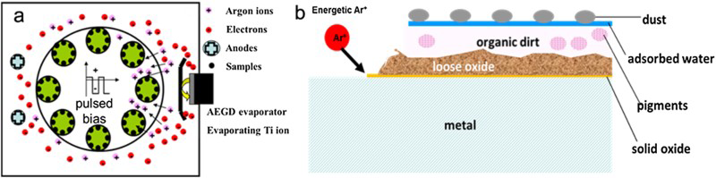
Characterization
Phases and crystallite size of the coatings were determined by a Bruker D8 ADVANCE X-ray diffraction (XRD) with the Cu Kα (λ = 0.15418 nm) radiation, at 40 kV and 40 mA in a 2θ range of 30–90° using a step size of 0.02°. The surface microstructures were investigated by a Zeiss SmartSEM V05.06 field emission scanning electron microscope (FE-SEM) fitted with an energy-dispersive spectrometer, and the surface roughness was measured by a BMT SMS Expert 3-D model optical profilometer. The cross-sectional microstructures were investigated by a Leica DMIRM optical microscope for low-magnification observation and the SEM for high-magnification observation. The chemical compositions of the coatings were determined by a Shimadzu EPMA-1600 electron probe micro-analyser (EPMA). The microhardness of the specimens was measured by a Shimadzu HMV-2T micro Vickers tester with a load of 50 g for 10 s and estimated by an average value from five measured points. Hardness Rockwell C indentation measurements were conducted to evaluate the coatings adhesion according to the VDI standard 3198. The indentation profiles were characterized by the 3-D model optical profilometer to evaluate the load-bearing capacity. Tribological studies were carried out using a Bruker UMT-3 wear testing machine with a 4-mm diameter silicon nitride (Si3N4) ball as counterpart at room temperature. The testing parameters were as follows: loading 5N, linear speed 10 cm s−1, rotational diameter 7 mm and sliding for 10,000 cycles (∼220 m in the sliding distance). The wear tracks of the worn surfaces were investigated by the 3-D model optical profilometer. The potentiodynamic polarisation tests of the duplex-treated TiN coating and the substrate were carried out using a CHI660D electrochemical analyzer in 3.5% NaCl solutions to investigate electrochemical behaviour. The potential of the electrodes was swept from an initial potential of −1200 mV versus Ecorr to a final potential of 200 mVSCE at a rate of 0.2 mV s−1.
Results and discussion
Microstructure analysis
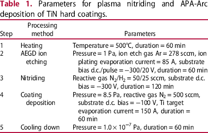
Figure 2 shows the diffraction patterns of the duplex-treated TiN and the monolayered TiN coatings. The duplex-treated TiN coating (Figure 2(a)) consists of α-Fe (ICDD #006-0696), γ′-Fe4N (ICDD #077-2006), δ-Ti2N (ICDD #077-1893), and a small quantity of TiN (ICDD #038-1420) phase and Ti phase (ICDD #044-1294). But, the monolayer TiN coating (Figure 2(b)) consists of TiN phase and α-Fe phase from the substrate. The reflections of the Fe4N phase well match with the standard diffraction peaks (with first to fourth strongest diffraction peak at 2θ = 41.17°, 84.65°, 47.91° and 70.06°, respectively) of the ICDD card, which revealed that the compound layer obtained during the plasma nitriding process consisted of neither Fe2N/Fe3N nor ε-Fe2-3N phase but the γ′-Fe4N (face-centred cubic, FCC) phase [10]. The crystallite size of duplex-treated TiN coating was determined to be ∼42 nm according to the Williamson-Hall plot method [17]. The chemical composition of TiN film depends on the conditions of deposition and in accordance with the following formulas [18]:
XRD analysis of the duplex-treated TiN coating (a) and the monolayer TiN coating (b).


Therefore, the final coating composition depends on the rate of condensation of titanium on the substrate and the partial pressure of nitrogen, as well as the degree of ionisation [19]. In the Ti–N phase diagram, TiN (FCC) can be formed over a broad nitrogen concentration range (at 500°C, 30 at.-% ∼ 50 at.-% N), while Ti2N (tetragonal) has a well-defined nitrogen concentration of 25 at.-%. So, most coatings consist of multiphase (Ti–TiN–TiN2) in which Ti2N is the most abundant phase [18]. This phenomenon is in accordance with our findings of the duplex-treated TiN coating. It was revealed in Patel et al. [18] that the deposition parameters, such as lower voltage, lower temperature, control over partial pressure of N2 and higher current favours the formation of substoichiometric Ti2N thin film.
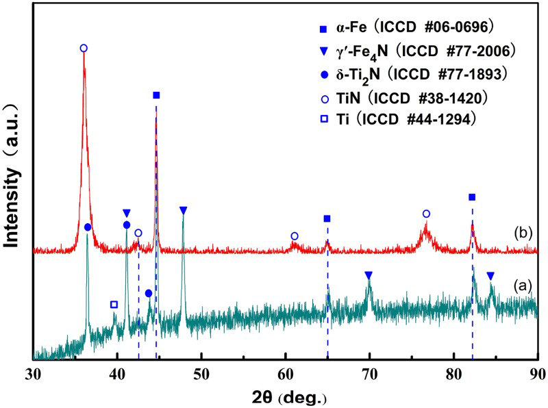
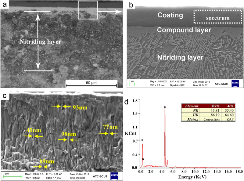
Figure 3 shows surface morphologies of the duplex-treated TiN coating. The micropores and macroparticles on the coating surface are smaller than 2 μm (Figure 3(a)), the surface roughness is about 160 nm (Figure 3(b)). The cross-sectional microstructures of the coating exhibit three distinctive zones (Figure 4(a)), including ∼4.1 μm TiN coating, 1–3 μm compound layer and ∼50 μm nitriding layer in thickness. With the assistance of plasma enhancement in the APA-Arc process, the deposition rate reached 4.1 μm h−1, higher than traditional arc technologies. Figure 4(c) reveals the presence of highly dense columnar nanocrystallines with a size of 40–100 nm in the duplex-treated TiN coating. The quantitative element analysis from the cross-section of the coating was determined by the EPMA analysis (Figure 4(d)). The Ti/N atomic ratio in TiN coating is 64.6: 35.4, approximately 2:1, in accordance with the δ-Ti2N main phase in XRD pattern (Figure 2(a)). The γ′-Fe4N compound layer is favourable over the ε-Fe3N or the biphasic (ε-Fe3N and γ′-Fe4N) layers in low alloy steels, because it makes great contribution to a higher hardness with wear resistance of the nitriding layer and a better adhesion for the coating [10,20]. The nitriding layer reaches ∼50 μm in thickness (Figure 4(a)) after 2-hour nitriding treatment, so the plasma nitriding rate reached 25 μm h−1, which is much higher than the traditional nitriding techniques. A nitrogen–hydrogen gas mixture can enhance nitriding efficiency in comparison with the treatment in the pure nitrogen under the same conditions. This can be explained as follows: First, hydrogen atoms have strong deoxidation ability, the enhanced nitriding can be caused by the interaction of hydrogen with the nitrified surface, which leads to probable surface oxide reductions and possible increase in the surface sticking coefficient for nitrogen. Second, the enhanced nitriding efficiency is also explained by increased excitation of nitrogen species in the discharge. Hovorka et al. [14] revealed that the addition of H2 into the gas mixture leads to an expected increase in the ion current density Js on the substrate, such as the Js
increases from 0.60 mA cm−2 for pure nitrogen to 0.80 mA cm−2 for nitrogen–hydrogen gas mixture (90% N2 + 10% H2). This effect is caused by enlarged excitation of nitrogen species due to the changes in ionisation mechanisms, leading to excitation transfers between N2 and H2 molecules.
Surface morphologies (a) and 3-D topography image (b) of the duplex-treated TiN coating. (a) Optical and (b, c) SEM microstructures of the cross-section of duplex-treated Ti2N coating; and (d) cross-sectional EPMA analysis of duplex-treated TiN coating.
Hardness analysis
In a microhardness measurement, when the indentation depth reaches more than 10% of the thickness of the coating, the obtained value was influenced by the substrate and not accurate. To decrease the influence of the compound hardness, the intrinsic hardness measurement was adopted to value the hardness of the coatings according to the following formula [21]:
Microhardness across the sections of the duplex-treated TiN and monolayer TiN-coated specimens.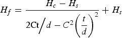
 is the intrinsic hardness of coating in HV,
 is the measured hardness in HV, t is the thickness of coating in μm, d is the depth of indentation in μm and C is equal to
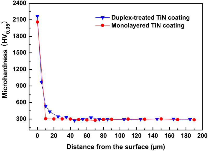
 . The results show that the intrinsic hardness of duplex-treated TiN coating reaches 2166 HV0.05, while the TiN coating merely reaches 2037 HV0.05. Therefore, the hardness of duplex-treated TiN coating was enhanced by the nitriding layer due to the increased bearing capacity. Besides, based on the dislocation blocking by Hall–Petch effect, the presence of nanocrystallines in the coating also accounts for increased hardness. The microhardness profile taken from the cross-section is shown in Figure 5. The curve of the duplex-treated TiN coating was divided into three distinct parts: the TiN coating, nitriding zone and substrate. The nitriding zone reached 1000 HV0.05 and about 50 μm in depth, which served as a transition zone between the harder coating and the softer substrate. It could relieve the ‘eggshell-like’ failure mechanisms of the hard coatings, and then enhance the hardness as well as plastic deformation capacity of the coating-substrate system. However, the monolayer TiN coating suffers from the saltation of hardness at the interface. High residual stress may also well form, which would result in poor adhesion and insufficient bearing capacity.
Adhesion and load-bearing capacity analysis
The results of Rockwell C indentation tests are applied to evaluate the adhesion strength and the load-bearing capacity. As shown in Figure 6, the in situ duplex-treated TiN coating, almost without any cracking, is HF1 level, while the monolayer TiN coating with some slight radial crackings around the crater is HF1∼HF2 level. As reported in Patel et al. [18], the Ti2N phase-based thin films have much lower residual stresses than TiN phase-based films, the duplex-treated TiN coating mainly consists of Ti2N phase (as shown in Figure 2), so duplex-treated TiN coating presents novel adhesion strength. Meanwhile, the nitriding layer and γ′-Fe4N compound layer would also lead to better adhesion of the duplex-treated TiN coating. The fine-grained and nano-sized grains in the coating caused the enhancement in the stress release path, which could also make a contribution to the adhesion and plastic deformation [22]. The AEGD ion etching process and in situ treatment avoided the pollutions and provided fresh surfaces for coating deposition, which improved the adhesion of coatings.
Indentation images and corresponding cross-sectional profiles of the (a, b) duplex-treated TiN and (c, d) monolayer TiN-coated specimens.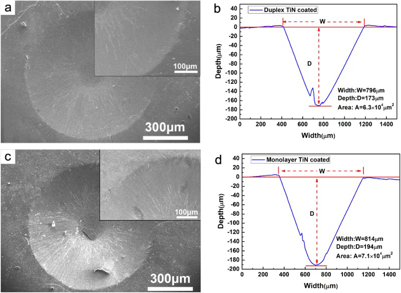
With the same loading force (150 kgf), the indentation depth, width and area of duplex-treated TiN hard coating are 173 μm, 796 μm and 6.3 × 104 μm2, respectively (Figure 6(b)). In contrast, the indentation depth, width and area of non-nitrided TiN monolayer reaches 194 μm, 814 μm and 7.1 × 104 μm2, respectively (Figure 6(d)). In comparison to monolayer TiN-coated specimen, the indentation depth of duplex-treated TiN specimen decreased by about 10.8% and the indentation profile area decreased by 11.3%. It indicated that the nitriding process has effectively increased the surface strength and load-bearing capacity of the substrate-coating systems.
Tribological properties analysis
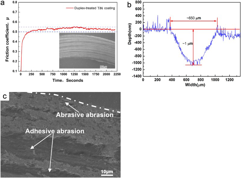
Figure 7 shows the friction coefficient of duplex-treated TiN coating is 0.54 (Figure 7(a)), and a precise wear track profile was carried out using a 3D model optical profilometer instrument to calculate area (A) of the wear track (Figure 7(b)). The wear track is about 650 μm in width and about 1 μm in depth. The wear rate coefficient (Kc) was calculated using the following formula [10,23]:
Tribological properties of the duplex-treated TiN coating: (a) friction coefficient, (b) sectional wear track morphology and (c) SEM morphology of wear track.
Corrosion resistance analysis
Potentiodynamic anode polarisation curves of the duplex-treated TiN coating and substrate are illustrated in Figure 8. The substrate has a low corrosion potential (Ecorr) with −840.4 mVSCE in 3.5% NaCl solution; nevertheless, the coating shows a nobler corrosion potential with Ecorr = −131.8VSCE. Hence, the corrosion potential of the TiN coating increased by 708.6 mVSCE. Meanwhile, the corrosion current density (Icorr) of the coatings (5.556 μA cm−2) decreased more than one order of magnitude, compared with the substrate (53.39 μA cm−2). The corrosion resistance of the substrate was improved to a great extent, because the TiN coating acted as a chemical barrier to prevent the corrosion of the inner substrate, and the γ′-Fe4N compound layer could raise the corrosion potential of the α-Fe and improve the corrosion resistance of sub-surface of the substrate.
Potentiodynamic polarisation curves of the substrate and the duplex-treated TiN coating.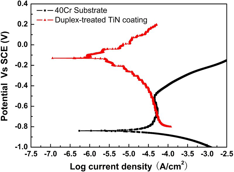
Conclusions
The duplex-treated TiN coating could be successfully deposited by the two-hour plasma nitriding and in situ one-hour APA-Arc technology. A few highlights can be summarised as follows:
Owing to the ion etch-cleaning process prior to the duplex treatment and the γ′-Fe4N phase formed in the compound layer, the adhesion strength level of the nanocrystalline TiN coating reaches HF1. The indentation depth and indentation profile area of duplex-treated TiN specimen decreased by more than 10% in comparison to that of monolayer TiN-coated specimen, under the same force loading (150 kgf) condition. Therefore, the nitriding process has effectively increased the surface strength and load-bearing capacity of the substrate-coating systems. The instinct hardness reaches 2166 HV0.05 and the wear rate coefficient of the TiN coating is sufficiently as low as 8.30 × 10⁻⁹ mm−3 Nm−1. Moreover, the TiN coating has significantly improved the corrosion resistance with high corrosion potentials (Ecorr = −131.8 mVSCE) and low corrosion currents (Icorr = 5.556 μA cm−2).
Footnotes
Disclosure statement
No potential conflict of interest was reported by the authors.