
Abstract
NiCr amorphous alloy coatings were deposited by magnetron sputtering at different sputtering current for corrosion resistance. X-ray diffraction performed that the coating was constituted of nearly amorphous phase and nanocrystalline phase. The corrosion resistance of coatings were tested by the copper accelerated acetate spray (CASS) test and in the 3.5wt% NaCl solution, respectively. Corrosion behaviours of coatings were also examined in NaCl 3.5 wt% electrolyte by electrochemical workstation. The results indicate that the self-corrosion potential of the NiCr amorphous coatings shifted to more positive potential compared to crystalline NiCr coating, which indicates that the NiCr amorphous coating has more excellent corrosion resistance, especially the coating obtained under the sputtering current of 30 A. At this time, the corrosion potential was −31 mV, and the corrosion current density was 0.13 μA cm−2, which could supply a reference for practical anti-corrosion application in pumps, ship impellers and automobile hubs.
Introduction
NiCr alloy coatings have a low-temperature coefficient of resistance and large electrical resistivity, so the importance and technical application as a resistor [1,2] in the electronics industry has increased [3]. At the same time, NiCr coatings are widely used in coal-fired boilers [4,5], ship impellers and other components [6,7] because of their good oxidation resistance, high thermal stability and corrosion resistance [8,9]. There are several ways to achieve high-performance coatings. One method is to increase performance by preparing a highly amorphous coating. Zhang et al. [10] prepared high-amorphous aluminium-based amorphous/nanocrystalline coatings on aluminium alloy surfaces using high-speed air–fuel spraying, which showed good corrosion resistance in the electrolyte. Meanwhile, the performance of the coating can also be improved by doping other elements. Weng et al. [11] reduce the isothermal oxidation rate of Ni-30Cr alloy by adding 0.5 wt% of Yttrium. Another improvement is to develop a two-layer coating. Matthews et al. [12] used High Velocity Air Fuel (HVAF) to prepare Cr3C2–NiCr coatings with excellent high-temperature erosion and wear resistance. However, in the study by Sidhu [13], thermal corrosion resistance was not as good as NiCr coating.
At present, there are many techniques for preparing coatings [14,15], electroplating technologies are currently one of the most commonly used methods for coating mechanical parts due to its good corrosion resistance and wear resistance. However, the electroplating process produces a large amount of sewage, which has an effect on the environment [16]. At the same time, some toxic substances are employed in the electroplating process, which also causes harm to the human body and leads to an increased risk of cancer [17]. Therefore, many advanced surface treatment methods for alternative plating techniques are also the hotspots and directions of contemporary research. As a new coating technology that replaces electroplating technology, magnetron sputtering technology has a simple sputtering process, which can achieve high reproducibility and can effectively control the target and film composition [18]. In addition, due to the higher energy of the sputtered atoms, the adhesion of the film to the substrate is better [19], a film having a smooth surface can be obtained, and it is suitable for mass production [20]. However, film obtained by sputtering generally has a crystal structure [2,19], and structural defects such as grain boundaries and second-phase particles exist. In order to satisfy the corrosion resistance, it is necessary in order to increase the sputtering time, but this causes waste of resources. It is still a stark challenge to obtain films that meet the requirements of corrosion resistance and will not waste resources during sputtering.
In recent years, the application of amorphous materials in the protection of mechanical parts has attracted widespread attention. Compared with traditional crystalline materials, the atomic arrangement of amorphous materials exhibits long-range disorder and short-range-ordered structures, so they have excellent physical properties (high magnetic permeability, high magnetic induction and low magnetic loss) and mechanical properties (low modulus of elasticity and high breaking strength). In particular, amorphous materials have significant corrosion resistance than crystalline metal due to the absence of grain boundaries, dislocations or interfacial defects [17,21]. Tavoosi et al. [22] used an electrodeposition method to obtain a completely amorphous Fe–NiCr coating excellent in corrosion resistance by modifying the current density.
To the best of the author's knowledge, the preparation of coatings in the previous studies is greater, and the preparation of NiCr amorphous coatings has rarely been reported. A nano-thickness NiCr amorphous coating can be deposited in a short time by magnetron sputtering. The polarization curve test showed that the coating has excellent corrosion resistance.
Experiment
Material and sample preparation
To prepare NiCr thin film, a NiCr alloy target (Ni:Cr = 80:20) was used. The substrate employed to depositing NiCr alloy coating was an aluminium alloy panel. Prior to magnetron sputtering, aluminium alloy panels were sonicated in acetone, ethanol and deionized water for 10 min, respectively, and then dried in an oven. A layer of epoxy resin was applied to the single crystal silicon wafer prior to deposition of the NiCr coating. The NiCr alloy coatings were deposited by direct current (DC) magnetron sputtering at room temperature for 120 s and sputtering current of 10, 20, 30, 40and 50 A, respectively, the argon flow rate was maintained at 200 sccm and the background vacuum was at 5 × 10⁻³ Pa.
Coating characterization
The phase structure of the target and the sputtered coatings were characterized by X-ray diffraction (XRD RigakuD/MAX 2500/PC) with a Cu–Kα radiation, and the scanning angle was ranged from 10 to 90° with a 5° min−1, and the accelerating voltage and applied current were 40 KV and 30 mA, respectively. The thickness of the coating was also measured using a step meter. The surface morphology of the NiCr coatings were tested by scanning electron microscopy (SEM; Zeiss, SUPRA55) equipped with energy-dispersive X-ray spectroscopy (EDS).
Corrosion test
Salt water immersion and copper accelerated acetate spray (CASS) test were used to recorded the corrosion behaviour of NiCr coatings. The specimens were soaked in 3.5 wt% NaCl solution for 2 months. The salt spray box used in the CASS test has a NaCl content of 50 g L−1, a CuCl2·2H2O content of 0.25 g L−1, 3.1–3.5 of pH, 50°C of the temperature and the time of 168 h. The polarization curves were performed in a typical three-electrode cell on an electrochemical workstation (CHI660E). NiCr alloy coating was sputtered on monocrystalline silicon and used as working electrode. The effective working area was 1 cm2. Platinum foil (1 cm × 1 cm × 0.01 cm) and saturated calomel electrode (SCE) were used as an auxiliary electrode and reference electrode, respectively. Electrolytes used are 3.5 wt% NaCl aqueous solutions prepared from reagent grade chemicals and distilled water. Polarization curves were recorded at a potential sweep rate of 10 mV s−1 after immersing the specimens for about 30 min when the open circuit potentials became almost steady [8].
Results and discussion
Microstructure of the coatings
In order to eliminate the influence of the amorphous structure in the epoxy layer, the nickel-chromium coating is directly deposited on the single-crystal silicon. Figure 1(a) showed the XRD patterns of NiCr alloy coatings with different sputtering current. Besides the peaks from the Si substrate at 2θ = 32.9 and 47.7°, the characteristic diffraction peak located at 44.3° corresponds to the peak of NiCr alloy target (210) (JCPDS: 26-0429) used in the magnetron sputtering. It indicates the NiCr alloy coatings have the same composition as the target. Meanwhile, diffuse reflection peak is observed, implying that the NiCr alloy coatings are composed of amorphous phase and crystal phase. Utilization peakfit software, the area of amorphous peak and crystallization peak are fitted and the area ratio of crystal to amorphous content is shown in Figure 1(b). The ratio increases with the increase of sputtering current until it reaches 40 A. When the sputtering current reaches 50 A, the ratio of content becomes gentle and decreases slightly, which implies the sputtering rate has reached a saturation state with the energy of the bombardment ions reaches a certain value.
(a) XRD patterns of NiCr target and coatings deposited at different current. (b) The plot of crystal/amorphous ratio (left axis) and grain size (right axis) versus sputtering current.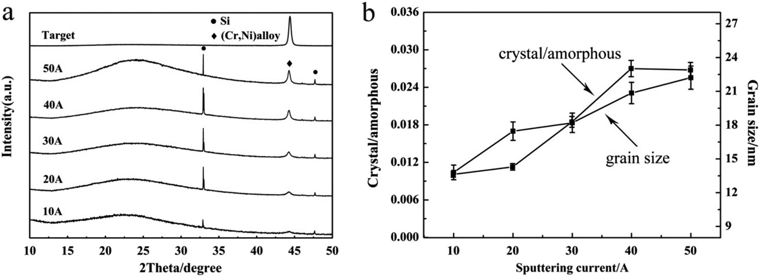
Based on the Debye–Scherrer formula, the grain size is also calculated shown in Figure 1(b).

It can be seen that the grain size increases with the increase of the sputtering current, especially, the grains grow slowly at 20–30 A, and the grain size is of 17–18 nm. When the sputtering current reaches 50 A, the grain size reaches about 22 nm. XRD data indicate that NiCr coating constituted of nearly amorphous phase and nanocrystalline phase was prepared efficiently.
Surface morphology of the coatings
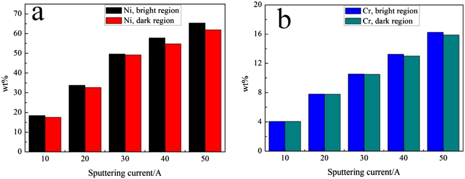
The surface morphology and EDS of the coatings sputtered at different current were shown in Figure 2. It can be seen that the surface of the coatings obtained at different current is smooth and dense, and the surface has different regions of bright and dark. At low sputtering current (10, 20, 30 A), the dark regions appear as spots, while at 10 A and 20 A, the dark regions increase with increasing current. However, when the sputtering current is increased to 30 A, the dark region is reduced. And when the sputtering current is increased to 40 A, the surface of the coating appears bright and dark strips instead of spots, and the dark region is significantly increased. Under the 50 A sputtering current, the dark region of the coating surface is both streaked and speckled, and the region is less than 40 A. The contents of Ni and Cr elements detected by EDS in the bright and dark regions were shown in Figure 3. It can be seen that with the increase of sputtering current, the Ni and Cr contents of bright and dark regions increase, while the Ni and Cr contents in bright regions are higher than those in dark regions. Moreover, O content in the bright region is lower than that in the dark region. For example, when the sputtering current is 30 A, O content in the bright region is 30.17 wt% less than 31.07 wt% of that in the dark region, indicating that the oxide formed on the dark region.
SEM images and EDS of NiCr coatings sputtered at different sputtering current. (a) 10 A, (b) 20 A, (c) 30 A, (d) 40 A, (e) 50 A and (f) target. Histogram of content distribution of different elements in bright and dark regions before coatings corrosion. (a) Ni and (b) Cr.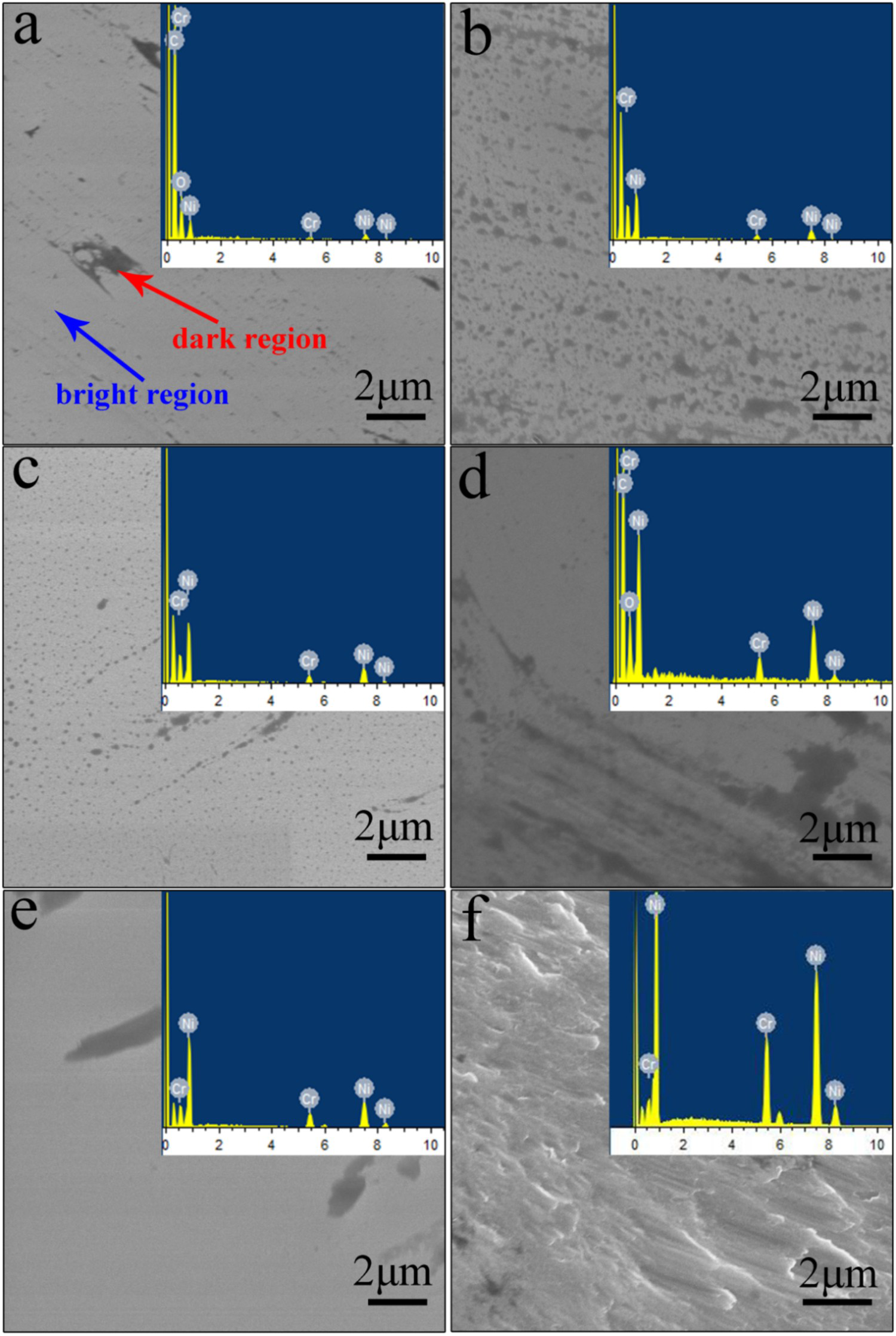
Cross-section of the coatings
The cross-section mapping of the coating obtained by sputtering at different current was shown in Figure 4. It can be seen from the cross-sectional view that the thickness of the NiCr coating is different at different current. The coating thickness is about 200 nm at 20 A, and the coating thickness is about 305 nm at 30 A. At 40 A, the coating thickness is about 415 nm. Moreover, it can be seen from the mapping diagram that Ni–Cr elements infiltrate into the organic layer, which reduces the surface tension between the metal coating and the organic layer.
The cross-section mapping of the coating obtained by sputtering at different current.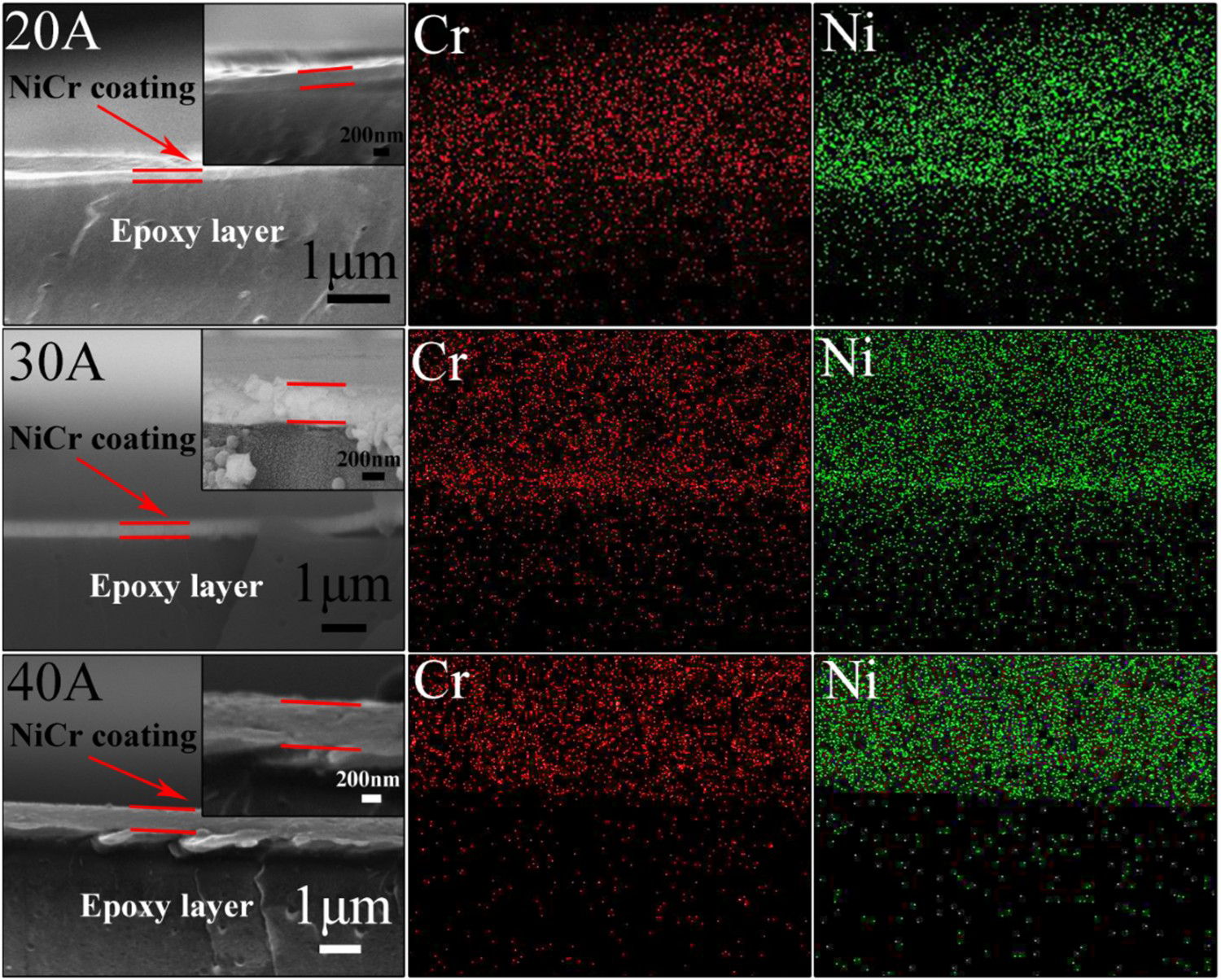
Thickness of the coatings
The film thickness statistics obtained by DC magnetron sputtering at different current measured by a step meter were shown in Figure 5. The thickness of film increases linearly with the increase of sputtering current except that the sputtering current is 50 A.
Line chart of the film thickness under different sputtering current.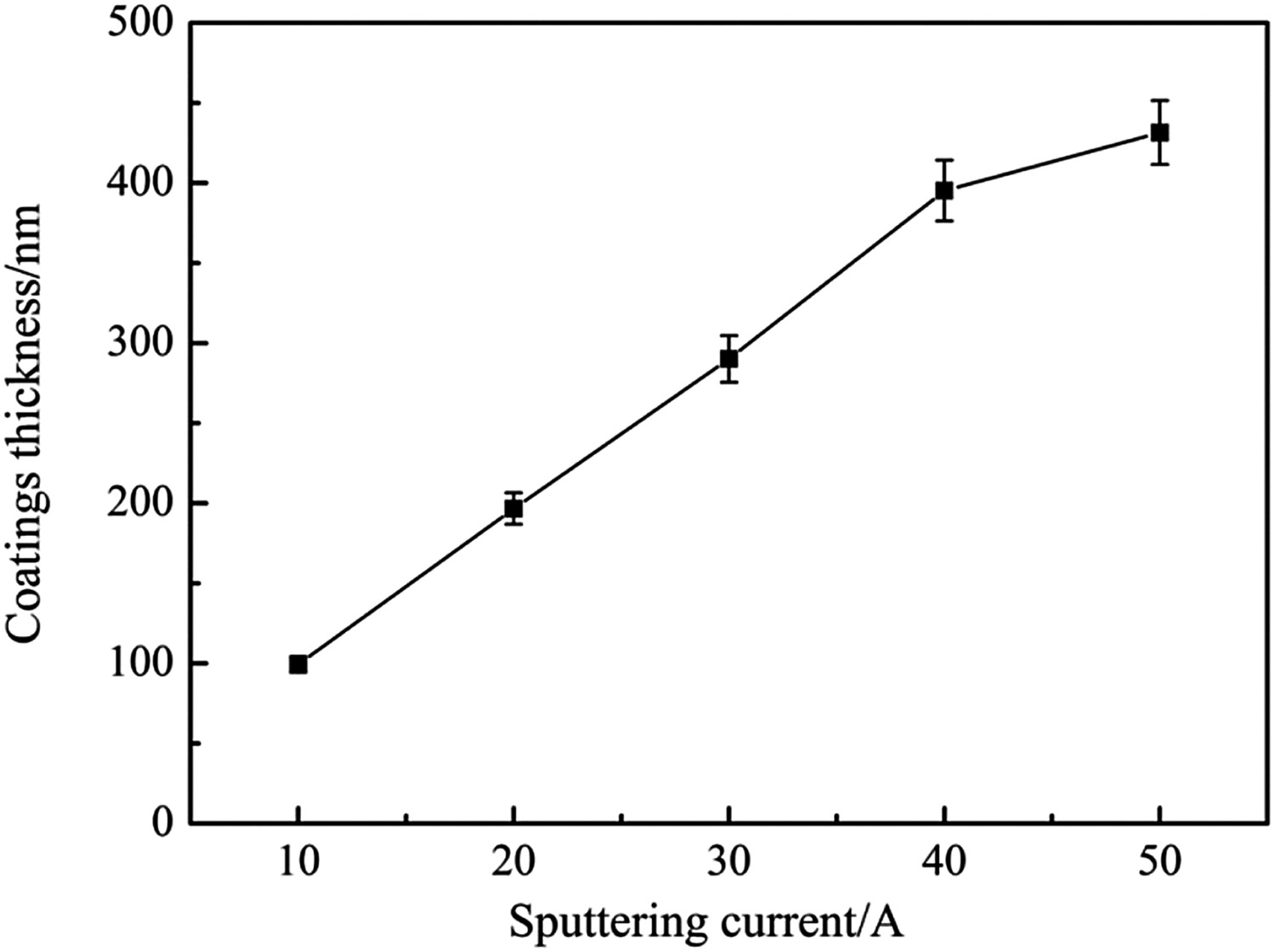
During DC magnetron sputtering, the sputtering rate initially increases exponentially with the bombardment ion energy obtained from the sputtering current and then gradually increases to a flat maximum and saturation state. If the sputtering current increases again, the sputtering rate will begin to decrease due to the ion implantation effect. Therefore, the thickness of the film obtained at 50 A current no longer increases linearly, which is further evidenced that the sputtering rate has reached a saturation state [23].
Corrosion resistance of the coatings
For the long-term study of the corrosion resistance of NiCr coatings, the salt water immersion test and CASS test were used, and the electrochemical properties of the coatings were tested to investigate the transient corrosion.
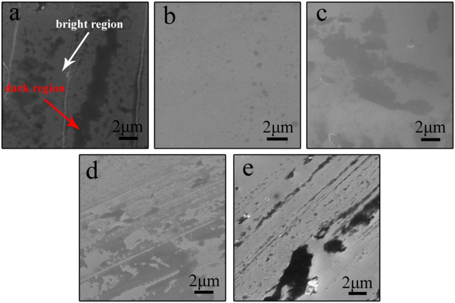
Figure 6 shows the surface morphology of the coatings after soaking for 2 months in a 3.5 wt% NaCl solution. Compared with the surface morphologies of the coatings before immersion in 3.5 wt% NaCl solution, corrosion occurs after immersion for 2 months but the degree of corrosion is different: coatings obtained at current of 20 and 30 A have relatively small areas of corrosion, and localized corrosion of coatings obtained at 10 and 40 A current is more severe. The coating obtained at a current of 50 A even showed pitting. Figure 7 shows the surface morphology of the coatings after the CASS test. The tested coatings also showed varying degrees of corrosion compared to the pre-test coatings: The coating at 20 A current has almost no corrosion, and the coatings under 10 and 30 A current have local corrosion, and the corrosion of the coating at 50 A is more serious. At 40 A, the surface of the coating layer is delaminated and peeling off.
SEM images of coatings sputtered at different sputtering current after soaking for 2 months in 3.5 wt% NaCl solution. (a) 10 A, (b) 20 A, (c) 30 A, (d) 40 A and (e) 50 A. SEM images of coatings sputtered at different sputtering current after CASS test. (a) 10 A, (b) 20 A, (c) 30 A, (d) 40 A and (e) 50 A.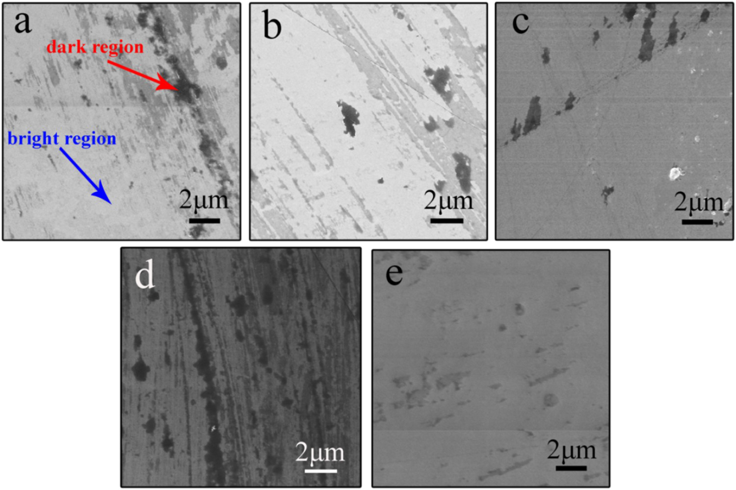
At the same time, the elemental distribution of the coating's surface was also examined using EDS. Ni/O, Cr/O weight ratios of coatings sputtered at different current were shown in Figure 8.
Ni/O weight ratio of coatings sputtered at different current: (a) bright region and (b) dark region. Cr/O weight ratio of coatings sputtered at different current: (a) bright region and (b) dark region.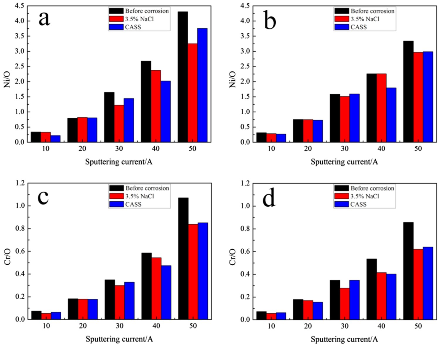
It can be seen that as the current increases, both Ni/O and Cr/O ratios increase in the bright and dark regions. When immersed in a 3.5 wt% NaCl solution or conducted a CASS test, Ni/O, Cr/O ratio decreased compared with that before the test, indicating that the content of O was relatively increased and the content of Ni was relatively decreased, so the surface of the coating was corroded. The figure shows that when the sputtering current is 20–30 A, the Ni/O and Cr/O ratio changes are smaller than those of the other current after immersion in 3.5 wt% NaCl solution or CASS test. Combined with SEM and energy spectrum analysis, the coating obtained at a sputtering current of 20–30 A has better corrosion resistance.
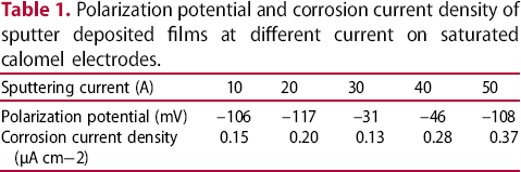
The polarization curves of NiCr amorphous–nanocrystalline sputtered coatings at different current were shown in Figure 9(a). The polarization potential and polarization current density values of NiCr sputtered coatings at different sputtering current relative to the SCE were presented in Table 1. From the comprehensive analysis of Figure 9(a) and Table 1, it can be seen that when the sputtering current is 30 A, the polarization potential of the sample to the saturated calomel electrode is −31 mV, and the polarization current density is 0.13 μA cm−2. It can be observed that when the sputtering current is changed, the polarization potential is changed from −31 to −117 mV, and the polarization current density is remarkably increased from 0.13 to 0.37 μA cm−2. This indicates that the coating obtained under 30 A sputtering current has better corrosion resistance. Comparison of corrosion potentials between the crystal structure of NiCr coatings prepared in other literatures [24-26] and NiCr coatings prepared in this experiment was shown in Figure 9(b). The corrosion potentials of the coatings in the experiment are both smaller than the potentials in other literatures, which indicates the coatings having amorphous–nanocrystalline structures deposited by DC magnetron sputtering in this experiment have the better corrosion resistance than the crystal structure NiCr coatings. Based on the results of the XRD image, it can be seen that the coating obtained in this experiment is a combination of amorphous and partial nanocrystals. The amorphous material has no structural defects such as grain boundaries, thereby preventing the penetration of the electrolyte and preventing the occurrence of corrosion.
(a) The polarization curves of NiCr sputtered coatings at different current and (b) Comparison of corrosion potentials between the crystal structure NiCr coatings prepared in other articles and NiCr coatings prepared in this experiment. Polarization potential and corrosion current density of sputter deposited films at different current on saturated calomel electrodes.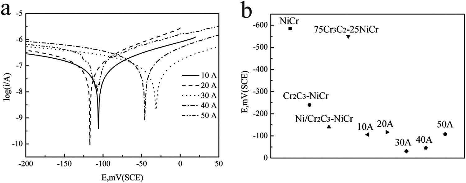
By considering all above features, it can be concluded that the coating obtained under the sputtering current of 20–30 A exhibits excellent corrosion resistance. Amorphous and nanocrystalline bonded coatings are more resistant to corrosion than pure crystalline coatings in 3.5 wt% NaCl solution. This is mainly attributed to the dense amorphous–nanocrystalline structure of the coating [27], which makes solution penetration difficult, and the amorphous coating does not have structural defects such as grain boundaries and second-phase particles, where corrosion preferentially occurs. However, the increase of the nanocrystalline content will increase the grain boundary volume fraction as the corrosion active site [22], so that when the current exceeds 30 A, the nanocrystal content increases but the corrosion resistance decreases. When the current is less than 20 A, the thickness of the coating is not sufficient to completely resist the corrosion of the electrolyte.
Conclusion
In conclusion, amorphous and nanocrystalline NiCr alloy coatings were successfully prepared by DC magnetron sputtering system. The coating has a dense amorphous–nanocrystalline structure and has no structural defects, so that it showed better corrosion resistance than the crystal structure NiCr coatings. Especially in the 30 A sputtering current, the coating obtained is more excellent in corrosion resistance. The corrosion potential was −31 mV, and the corrosion current density was 0.13 μA cm−2. Therefore, this NiCr coating with enhanced corrosion resistance is expected to be used in pumps, ship impellers and automobile hubs.
Footnotes
Disclosure statement
No potential conflict of interest was reported by the authors.