
Abstract
Investigation of tribological behaviour of NiCrSiBFe coating on SS 316L sliding against AISI 52100 bearing steel, alumina (Al2O3), and silicon nitride (Si3N4) under dry conditions carried out. Air Plasma Spraying (APS) and High Velocity Oxy Fuel (HVOF) thermal spraying methods used to deposit the coatings. The dry sliding wear tests were carried out with the ball on disc machine following the ASTM G99 standard and the normal loads used were 10N, 15N, and 20N along with the constant sliding velocity of 0.5 m s−1 at room temperature. The particle analysis, XRD, SEM, EDX, and nanoindentation were used for the characterisation of the powder, coatings, and worn surfaces. The spraying methods, counter materials, and normal loads were ranked based on the wear loss and coefficient of friction. The main wear mechanisms on the coating's wear track are abrasive and adhesive. The HVOF spraying method revealed enhanced wear resistance property as compared to the plasma-sprayed coating.
Introduction
Surface and environment interactions failed most of the mechanical components during service. The wear, corrosion, and oxidation are the phenomena for the degradation of components. The great significance is given to the surface treatment methods to improve wear, corrosion resistance and to reduce friction. Thermal spraying processes affect the performance of the same coating for different properties. Rathod et al. [1] compared the Cold Gas Dynamic Spray (CGDS) and HVOF-sprayed CoNiCrAlY coatings for corrosion and oxidation properties. The CGDS sprayed coating performed better in oxidation and poor in corrosion as compared to the HVOF-sprayed coating. The food processing industries, biomedical implants, and nuclear industries widely utilise the austenitic stainless steel. The tribological properties of austenitic SS need to improve using surface modification techniques [2]. Plasma and HVOF thermal spraying processes are the most adaptable coating techniques widely used to deposit metals, ceramics, and composites [3]. In plasma spraying process, the coating properties are reformed due to thermal energy while in the HVOF process, kinetic and thermal energy controls the properties of coatings [4]. NiCrSiBFe coatings have abundant potential in the petroleum and chemical industrial application due to the excellent corrosion and wear resistance [5]. The application of these coatings includes turbines blades, coal-fired boilers, heat exchangers, tools, extruders, and rolls for rolling mills, piston rods, roller tables, wearing plates, pump shafts, punches, and agriculture machinery [6,7]. The hard phases of chromium and boron in the NiCrSiBFe powder improves the hardness and the wear resistance of the coating. Chromium improves the high-temperature oxidation and corrosion resistance. Boron with eutectic phase reduces the melting point. Silicon improves the self-fluxing properties [8,9]. Some of the findings of the nickel-based coatings are as below. Miguel [6] found the spray and fused coating methods for NiCrBSi powder much suitable than the plasma and HVOF methods. For the spray and the fused process, the wear mechanism was adhesive. For the plasma-sprayed coating, the main wear mechanism was the splat delamination. The NiCrBSi powder composition was modified to assess the properties and the wear mechanisms of the coating in a few types of research. The NiCrBSi powder with 10% Mo addition when coated with a laser cladding process improve the wear resistance [10]. Adhesive/delamination wear mechanism observed for flame remelted supersonic plasma-sprayed NiCrBSi powder with 30% Mo coating under dry sliding wear test [11]. Cr3C2 addition in NiCrBSi powder produced excellent wear resistance coating and bond strength [12,13]. Plasma-sprayed NiCrBSi powder with 4% graphite addition improved the erosion resistance and microhardness [14]. An abrasive, adhesive, and oxidative wear mechanism exists for HVOF-sprayed composite coating of nickel-based powder and WC-Co [15]. The wear resistance is affected by various constituents, including the spraying parameters. The stand-off distance plays a significant role in erosion wear resistance property [16]. For satisfactory working of any tribological system, the knowledge of the correlation between processing parameters, mechanical properties, and wear behaviour is essential [17]. The wear resistance of the different coatings is influenced by various key factors which include counter body materials [18,19]. The normal load and speed change affect the wear resistance. The wear of a component inversely proportional to the hardness but to predict the wear rate, hardness is not sufficient. For impact wear, the shape, size, and hard phases distribution play an important role in wear rate than the hardness parameter [20]. The wear behaviour is closely associated with the plasticity index and the hardness to elasticity modulus ratio [21]. Usually, the laboratory tests conducted for the wear computation of coating and the wear behaviour of the material is recognised based on the results. Various tribological tests are existing. For significant interpretation, the selection of the most suitable test based on the mechanical system and operating condition is essential [22]. Some pieces of the literature have studied the tribological behaviour of nickel and WC-based coating under various test such as dry sliding wear test [23-25], abrasive wear test [26], solid particle erosion test [13,27], cavitation erosion test [23,28], and slurry jet liquid impingement test [29].
The focus of this paper is to investigate the dry sliding wear performance of NiCrBSiFe coating obtained by plasma and HVOF-sprayed process, against AISI 52100 bearing steel, alumina, and silicon nitride as a counter material. Using ASTM G99 standard, the experiments conducted at 10N, 15N, 20N normal load and 0.5 m s−1 sliding velocity. The powder particle size, coating microstructure, coating phases, porosity, surface roughness, and the nano hardness were determined. The investigation for the effect of the counter materials, coating processes, and normal loads were carried out. The experimental results and worn track morphology were correlated.
Experiment details
Coating preparation
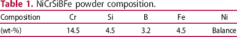
NiCrSiBFe powder composition.
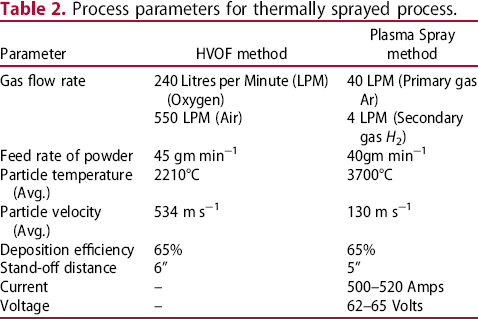
Process parameters for thermally sprayed process.
Characterisation
Laser diffraction analysis carried out to check the particle size variation in the NiCrSiBFe powder. EMPYREAN diffractometer system used to perform XRD analysis and to obtain the phase composition in the powder and coatings. Continuous scan type, Cu-Kα irradiation (λ = 1.54060 A°) with the 2θ range at 20°–90° with 0.02° step size used for X-ray diffraction. The microstructures of the coating and worn surfaces were analysed with Carl Zeiss (Gemini SEM 300) scanning electron microscope and by using energy-dispersive X-ray spectroscopy (EDX). Nanoindentation test carried out to determine the hardness and elasticity modulus of the coatings. To measure the volume fraction of pores, porosity analysis of the coated samples at different locations was carried out using ImageJ software by following an image thresholding procedure.
Tribological testing
A pin on disc machine (TR-20LE CHM-800, DUCOM) was used to conduct dry sliding wear tests at room temperature. The surface roughness of the as-sprayed disc measured at eight different locations using roughness tester. The average surface roughness value of as-sprayed coating measured as 2.307 and 5.87 μm for plasma-sprayed and HVOF-sprayed coating samples. After electro-polishing of the as-sprayed disc, the average roughness obtained as 0.3365 μm for plasma-sprayed and 0.3002 μm for HVOF-sprayed NiCrSiBFe coating. Silicon nitride, Alumina, and AISI 52100 bearing steel balls of 10 mm diameter having hardness value as 1580HV, 1440HV, and 875HV, respectively used as a counter surface. Owing to chemically inertness, these counter materials do not produce any chemical interactions which help in the interpretation of wear mechanisms [30]. Samples cleaned with ethanol before the performance of experiments. The sliding velocity of 0.5 m s−1 and a normal load of 10N, 15N, and 20N used for experimentation. The ASTM G99 standard procedure followed to perform experiments. Wear and coefficient of friction values recorded and analysed.
Result and discussion
Microstructural characterisation
From the laser diffraction method, the mean size of the powder particle found to be 28 μm. The particle size distribution of the gas atomised NiCrSiBFe powder shown in Figure 1.
Particle size distribution curve for NiCrBSiFe powder.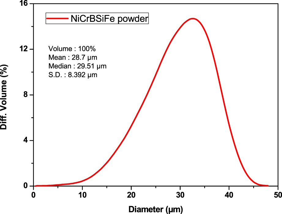
From the laser diffraction method, the mean size of the powder particle found to be 28.7 μm. The particle size distribution of the gas atomised NiCrSiBFe powder shown in Figure 1. By using X-ray diffraction analysis, powder phase compositions of the powder, HVOF and plasma-sprayed coatings obtained. Figure 2 displays the XRD pattern of the NiCrSiBFe powder, as-sprayed coated samples by plasma and HVOF-sprayed methods. Phase compositions for all three cases observed as Ni, Cr3Si, Ni2B, CrB, and Ni31Si12 that is lamellae of single-phase gamma.
XRD graph of NiCrSiBFe powder, HVOF-sprayed coating, plasma-sprayed coating.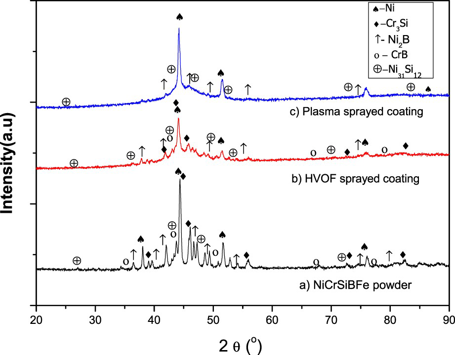
For plasma-sprayed coating CrB phase was not present. The key element found in the coating was nickel due to the high amount in the feedstock powder. Silicate crystals and boride crystals exist in the coatings. Owing to low stream temperature in HVOF-sprayed coatings, minor phase changes observed. The XRD pattern shows high peaks at 44.3° diffraction angle (2θ) and sharp peaks at some angles conforming to the crystalline phases. The crystalline phases and amorphous phases exist together in the coating as crystalline phases recognised as γ (Fe, Ni) face centred cubic solid solution phase, Body Centred Cubic (BCC) α-Fe phase and Fe2B phase. The observed phase results in the XRD graph match the phase results in the literature by Zórawski and Skrzypek [31].
Figure 3 shows the coating thickness and SEM image of the plasma-sprayed NiCrSiBFe coating. The coating thickness range from 250 to 300 µm at a different location. A metallurgical bond formed between the surface of the substrate and the molten alloy powder through thermal spraying. Hence very dense, smooth, wear, and corrosion-resistant coatings formed. Splats due to molten particles, partially melted, and unmelted particles (globules), voids were observed similar to other thermally sprayed coatings. EDX analysis of elemental composition (wt-%) at different points carried out to confirm the composition.
Plasma-sprayed coating thickness and SEM micrographs.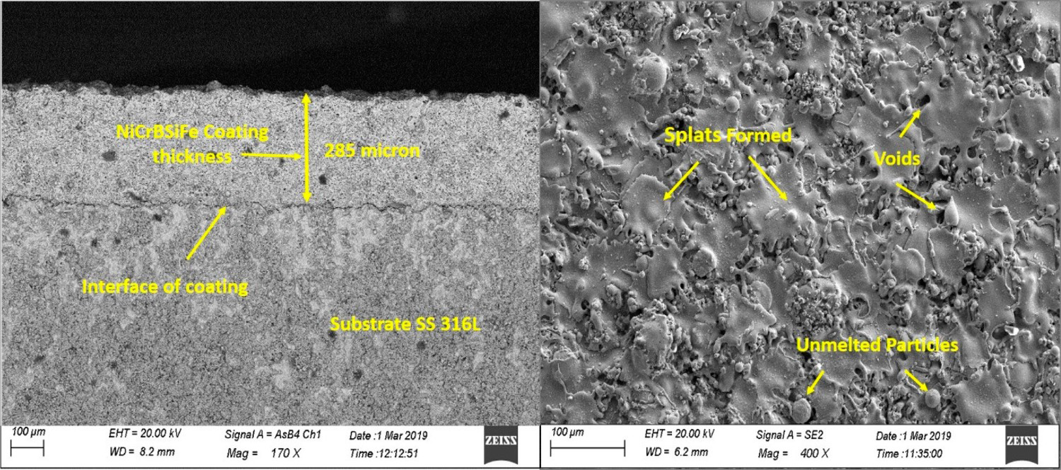
Figure 4 displays the EDX spectrum of the coating. The number indicates the weight percentage of components like nickel, chromium, ferrous, oxygen, and silicon. The observed composition material of the coated samples little varies from the powder composition as during coating process the particles exposed to high temperature. Figure 5 shows the coating thickness and SEM graph for HVOF-sprayed NiCrBSiFe powder. Melted particles and spherical nodules observed on the coating. The more dense coating with a small number of pores observed.
EDX analysis of plasma-sprayed coating. HVOF-sprayed coating thickness and SEM micrographs.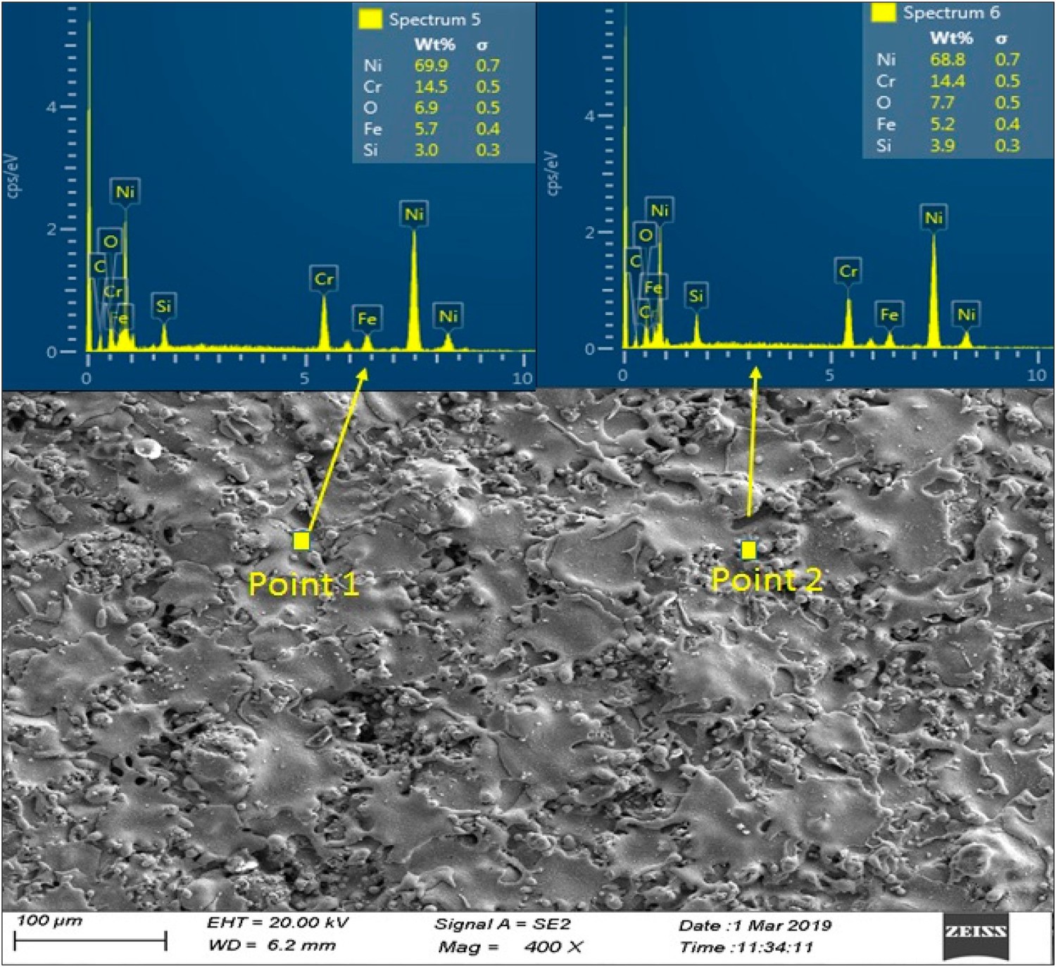
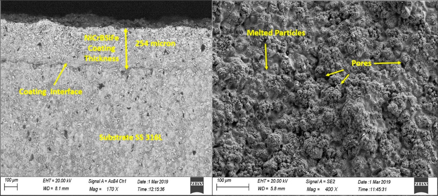
Figure 6 shows the EDX spectrum of the HVOF-sprayed coating and the weight percentage of the different elements presents.
EDX analysis of HVOF-sprayed coating.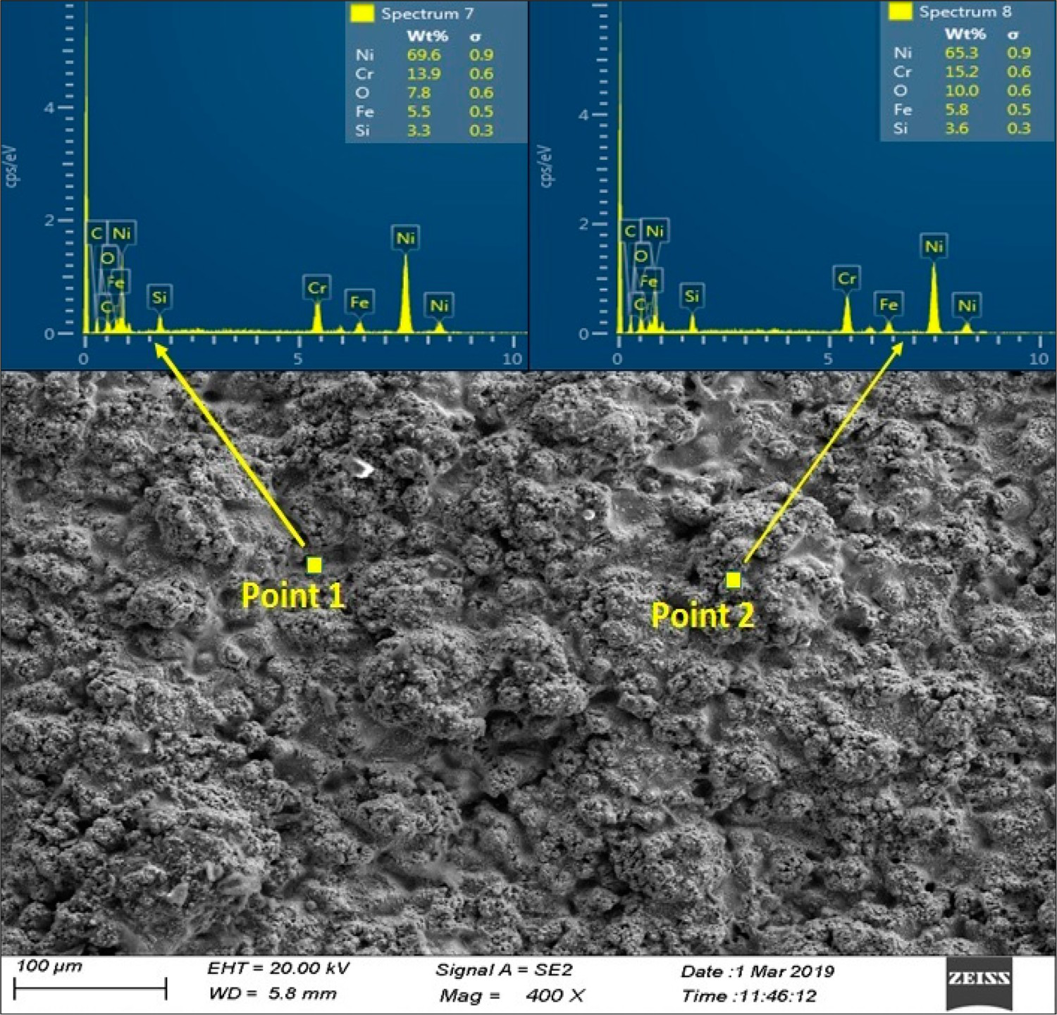
Properties of the NiCrBSiFe coatings.

The differences in the hardness and modulus of elasticity among the two coatings are primarily due to the process parameter, working principle, the adhesion, and size and quantity of precipitates. Because of the high thermal energy involved in the plasma process, the precipitates deteriorated and the hardness reduced. The HVOF coating sample has high hardness due to the high velocity involved. The small precipitates with more quantity perfectly spread in the coating to give better adhesion [6]. The H/E ratio indicates the coating ability to tolerate elastic deformation, which is slightly more for HVOF-sprayed than plasma-sprayed coating. The elastic energy storing ability that is H2/E ratio found 33% higher for the HVOF-sprayed coating than plasma-sprayed coating.
Friction and wear properties of coatings
The dry sliding tests results at room temperature are obtained for all combination of loads, counter materials, plasma-sprayed, and HVOF-sprayed samples. The wear depth and Coefficient of Friction (COF) profile for plasma-sprayed coating at 10N load against alumina, silicon nitride, and bearing steel shown in Figure 7(a–c), respectively. The greater fluctuations in wear depth and COF profile observed for silicon nitride than for the bearing steel and alumina counterpart. The plasma-sprayed coating shows minimum wear depth and the smallest coefficient of friction against the bearing steel counterpart. The wear depth and COF variation against different material was due to the difference in hardness of the counter material and wear mechanism.
Wear depth and COF profile of plasma-sprayed NiCrBSiFe Coating at 10N, (a) vs. alumina, (b) vs. silicon nitride, (c) vs. bearing Steel.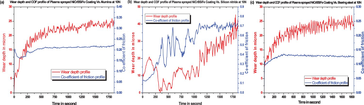
The wear depth and COF profile at 10N load for HVOF-sprayed coating against alumina, silicon nitride, and bearing steel are shown in Figure 8(a–c), respectively. The wear depth profile follows a parabolic pattern, as observed in the figure. Alumina counterpart shows a smaller amount of wear depth as compared to the bearing steel and silicon nitride material. The more fluctuations in the wear depth reading observed for silicon nitride material.
Wear depth and COF profile of HVOF-sprayed NiCrBSiFe Coating at 10N, (a) vs. alumina, (b) vs. silicon nitride, (c) vs. bearing steel.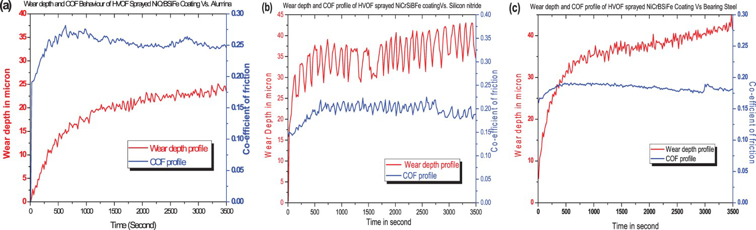
The coefficient for all the three material found stable over the sliding distance. For 52100 bearing steel, the COF value is least as compared to the alumina and silicon nitride material. For HVOF-sprayed coating, the COF against the bearing steel, silicon nitride, and alumina obtained as 0.16, 0.2, and 0.26, respectively. As compared to the plasma-sprayed coating the COF values and wear depth values were small under the similar operating conditions. It shows that the performance of the HVOF-sprayed coating against all these three counter material was better. All COF values lie in the range of 0.1–0.82 for various combinations, as shown in Figure 9. Correspond to plasma-sprayed coating and silicon nitride as a counter ball, the COF range from 0.5 to 0.7. The obtained results are found consistent with the literature.
Co-efficient of friction at 10N, 15N and 20N for different combinations.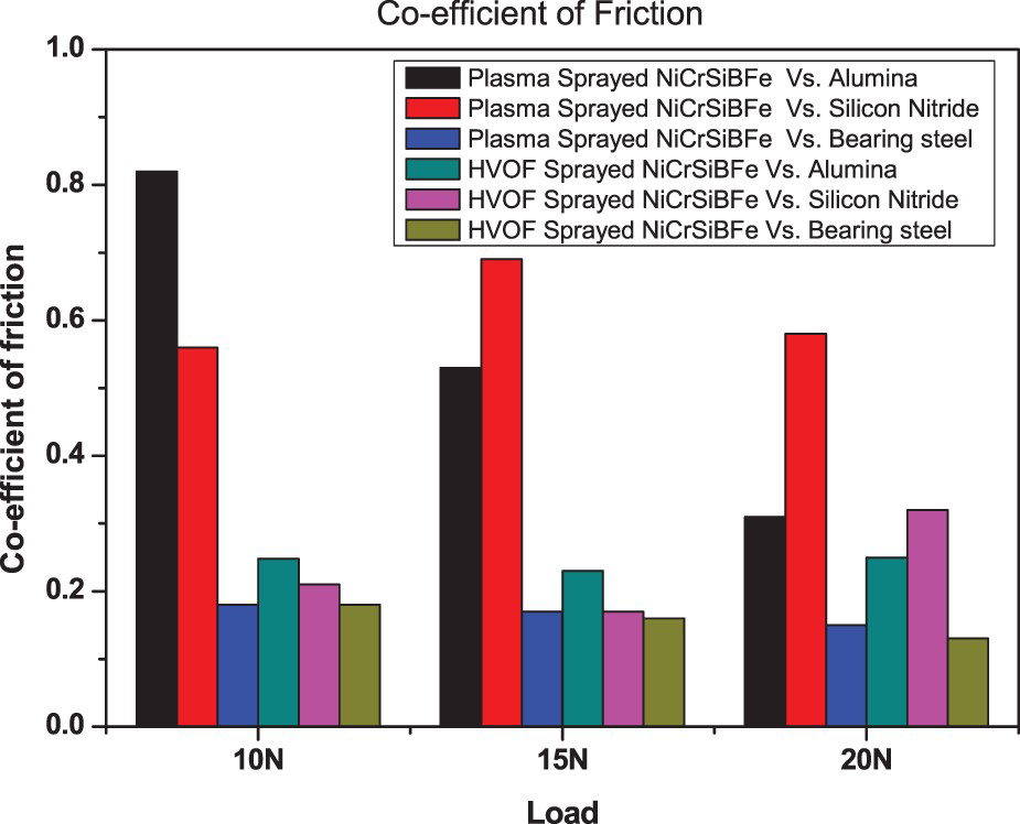
The friction coefficients for Al2O3 ball against plasma-sprayed NiCrBSi coating range from 0.63 to 0.70 [12,18]. The COF for HVOF-sprayed coating against all the counterpart materials ranges from 0.1 to 0.3, which is very small compared to the COF for plasma-sprayed coating. Which indicates the superior tribological performance of HVOF-sprayed coatings over the plasma-sprayed coating for the dry sliding wear test. High wear rate indicates the short life of a component. To understand the effect of the spraying process, the volumetric wear rate was determined. A counter ball and disc dissembled after running the test. The wear track on the disc examined microscopically. As per ASTM G99 method, the volume of the removed material from the coating surface calculated. The volume loss determined in cubic millimetres using an exact expression as given by the following equation:
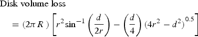
The track widths determined from the SEM image obtained by taking an average of three readings. The average specific wear rates determined from the results obtained for three different loads corresponding to each counter material.
Figure 10 shows the specific wear rate for plasma-sprayed and HVOF-sprayed NiCrBSiFe coating against alumina, silicon nitride and AISI 52100 bearing steel. The plasma-sprayed coating and the steel material counterpart gives the least wear rate while the wear rate for silicon nitride material with plasma coating found the highest magnitude. The wear rates found very high correspond to the plasma-sprayed coating. Which indicate the wear resistance is more for the HVOF-sprayed coating than the plasma coating for all the counter material used. The plasma-sprayed process could be the right choice for less harden counter material like the bearing steel, but not suitable for harder counter materials like alumina and silicon nitride. Table 4 shows the average specific wear rate determined for a different combination.
Specific wear rate for plasma and HVOF-sprayed coating. Specific wear rate for NiCrBSiFe powder coating.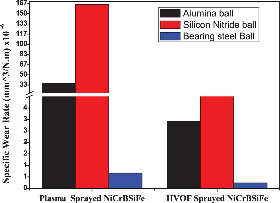
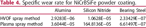
HVOF spray coating gives 2.83 times more wear resistance than the plasma-sprayed coating for 52100 bearing steel counter material. Similarly, the HVOF spray coating 12.3 and 155 times more wear resistance than the plasma-sprayed coating for alumina and silicon nitride counter material. Figure 11(a,b) shows the wear tracks and the wear mechanism for plasma-sprayed NiCrBSiFe powder coating at 10N load against silicon nitride material. Correspond to the silicon nitride counter material, abrasion marks, craters, debris, and plastically deformed surfaces detected on the track. Abrasive and adhesion wear phenomenon witnessed. More delamination and splat spalling took place in dry sliding wear of plasma-sprayed coating against silicon nitride.
WT for plasma-sprayed NiCrBSiFe vs. silicon nitride ball at 10N load (a) 76X, (b) 500X.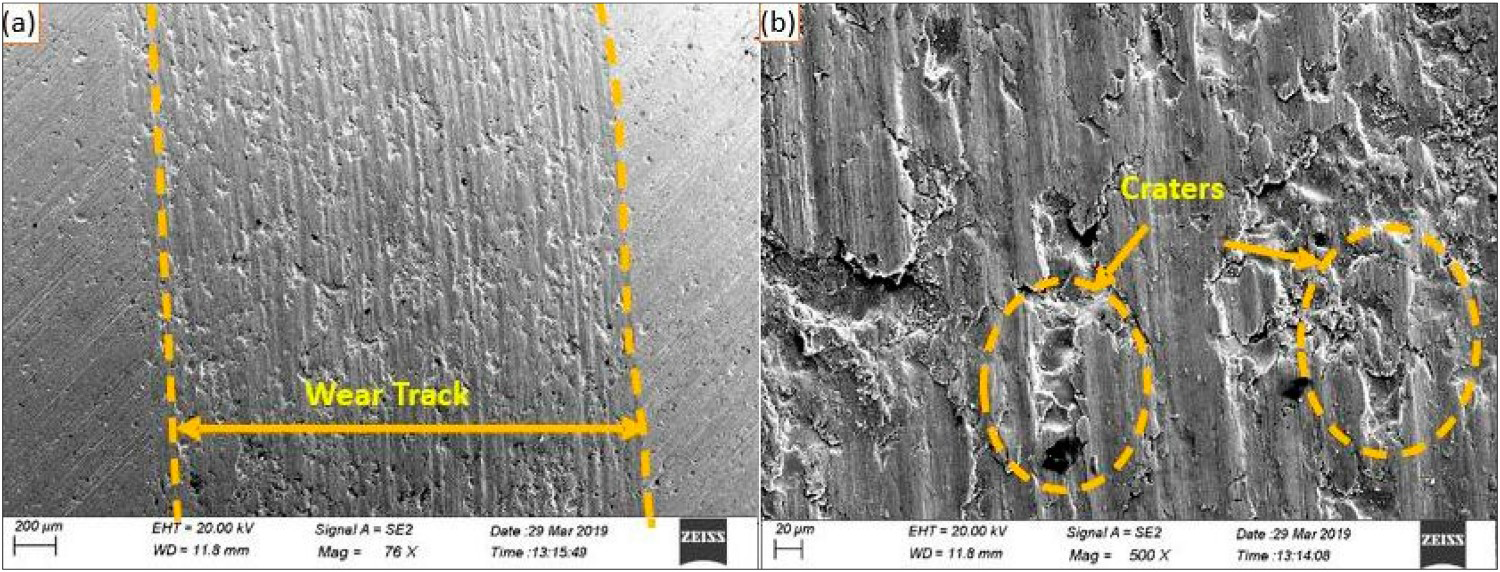
The alumina counter material produces abrasive and adhesive wear mechanism as observed from the track microstructure. Figure 12(a,b) shows the abrasion marks, craters, plastically deformed layers on the track surface with more adhesion of alumina particles from the counter surface. For plasma-sprayed coating against silicon nitride counter material, more craters observed on the track surface as compared to the track obtained by alumina material. The wear track is not fully visible at similar operating conditions against the bearing steel counter material which indicate the extent of wear is least. Figure 13(a,b) shows the small craters at higher magnification correspond to the plasma-sprayed coating against the bearing steel counter material.
WT for plasma-sprayed NiCrBSiFe vs. alumina ball at 10N load (a) 74X, (b) 500X. WT for plasma-sprayed NiCrBSiFe vs. 52100 bearing steel at 10N load (a) 72X, (b) 500X.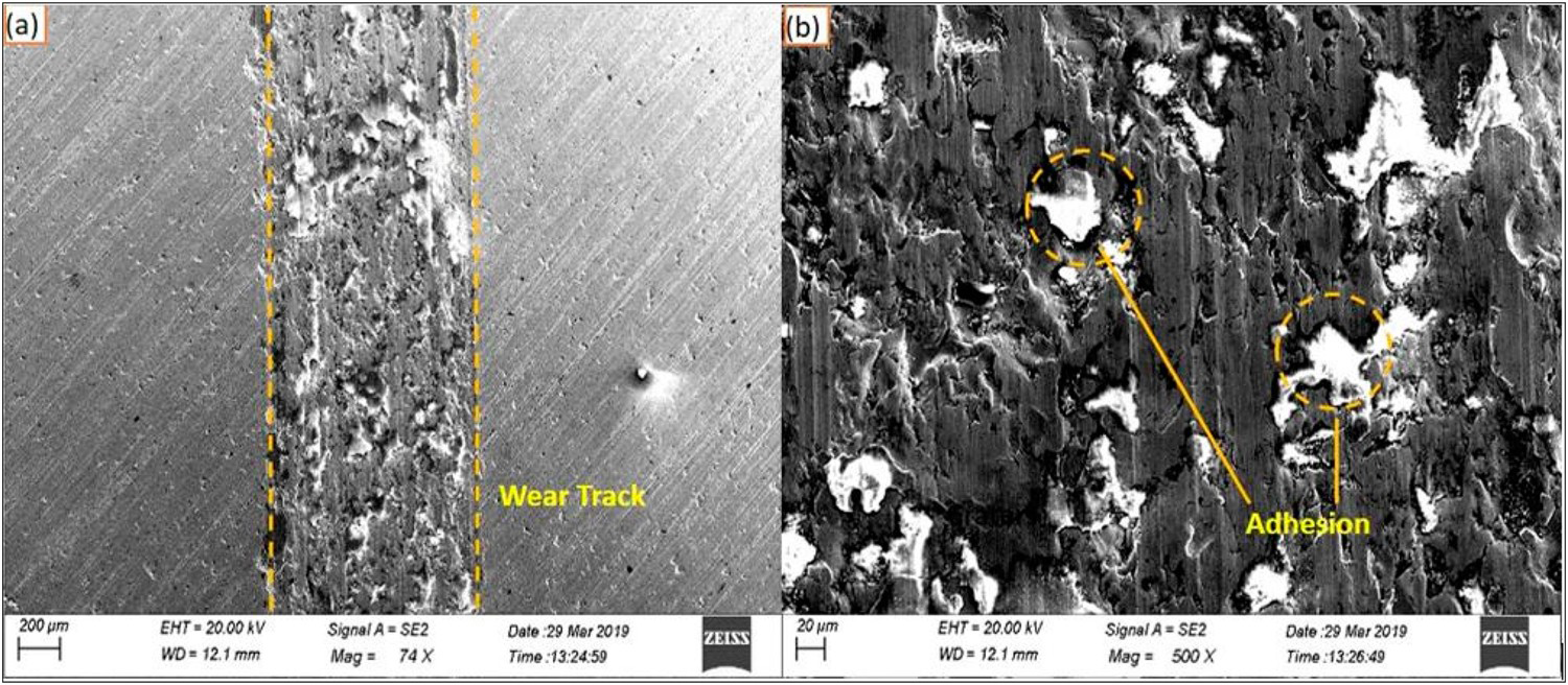
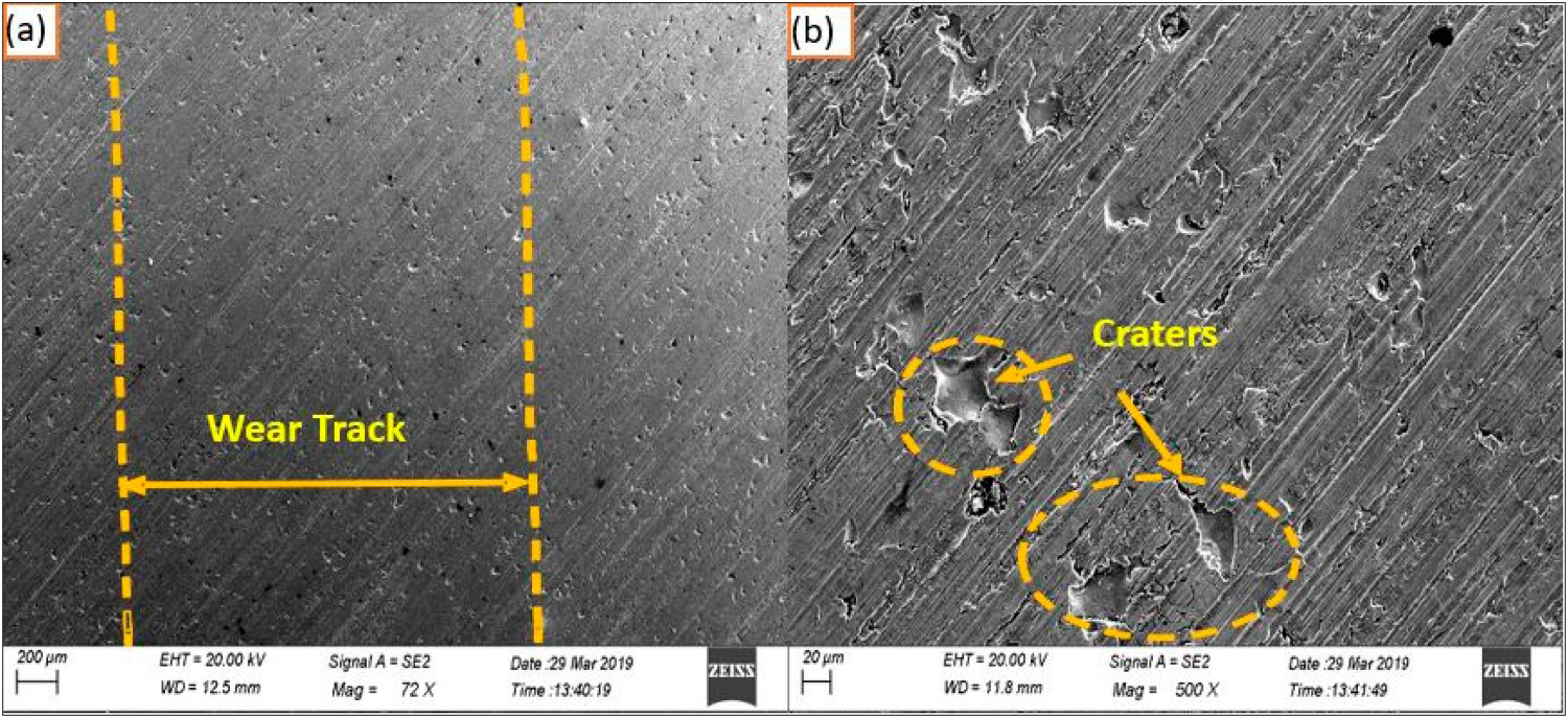
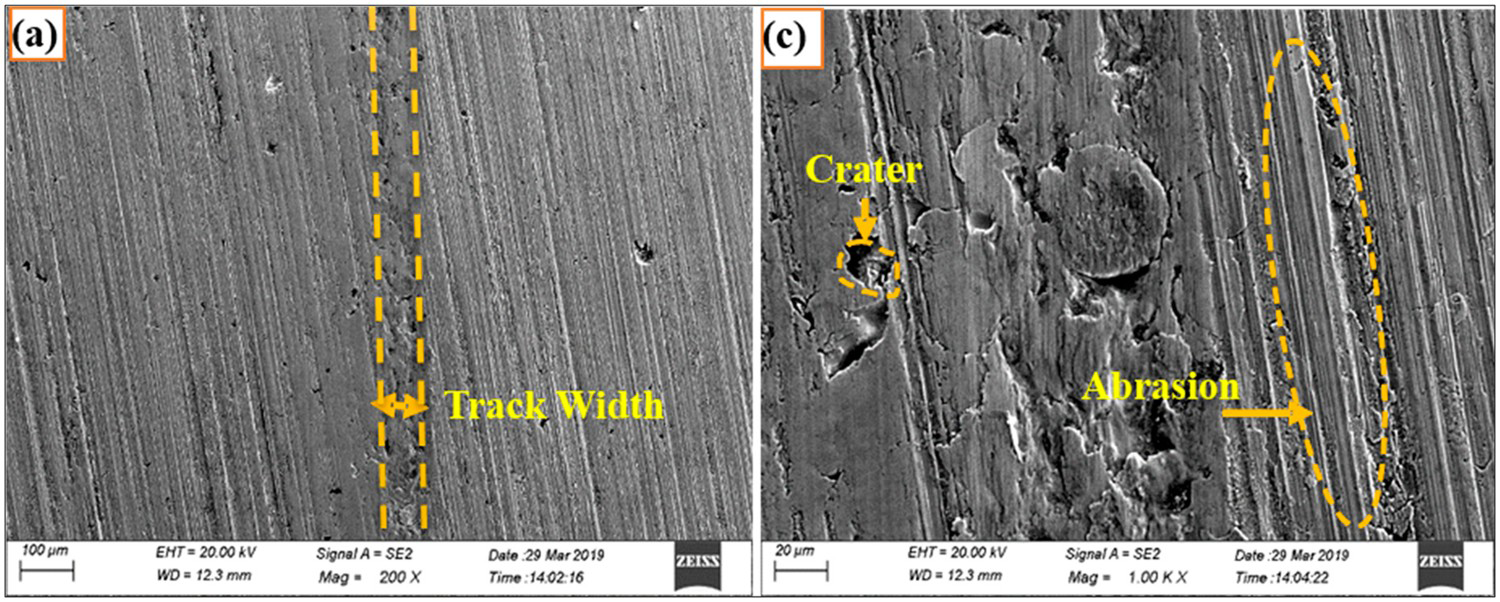
Figure 14(a,b) shows the wear track microstructure of the HVOF-sprayed coating surface against the alumina counter material at 10N load. The microstructure shows the ploughing marks, craters which indicate the abrasive failure and splat spalling as main wear. The wear track and the wear mechanism for silicon nitride counter ball with HVOF-sprayed coating is shown in Figure 15(a,b). The microstructure shows the adhesive and abrasive wear behaviour. The craters, abrasive impressions and adhesion marks observed on the wear track surface. Small micro-cracks, delamination, and splat spalling observed. The wear mechanism noticed from the micrographs seems to be almost same as reported in a few pieces of the literature including Bolelli et al. [30].
WT for HVOF-sprayed NiCrBSiFe vs. alumina at 10N load (a) 200X, (b) 1000X. WT for HVOF-sprayed NiCrBSiFe vs. silicon nitride at 10N load (a) 200X, (b) 1000X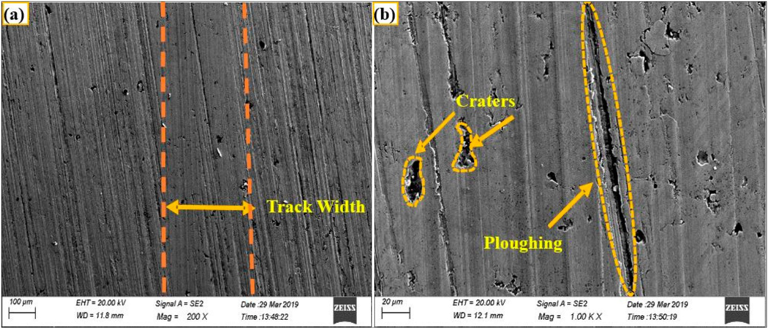
ANOVA analysis
Response table for S/N ratios for sliding wear loss and COF (Smaller is better).
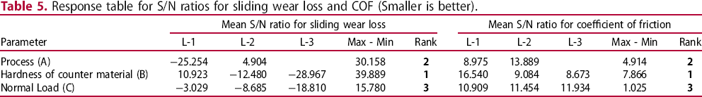
The order of influencing parameter on the wear loss and friction obtained as, Hardness of the counter material > Process of deposition > Normal load.
Figure 16 shows the main effect plot for S/N ratios corresponding to the sliding wear loss. From the main effect plot, the preferred parameters for minimum wear loss found as HVOF spraying method, the hardness of the counter surface (875 HV) and load (10N).
Main effect plot for S/N ratios corresponds to sliding wear loss.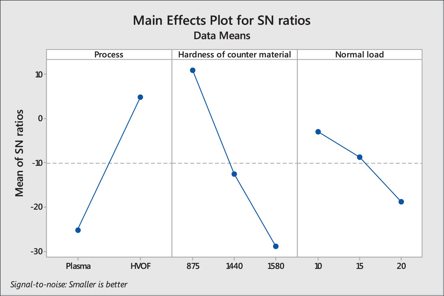
Conclusions
Corresponding to the wear experiments performed under the dry sliding condition at room temperature for plasma-sprayed and HVOF-sprayed NiCrSiBFe alloy powder on SS 316L substrate against AISI 52100 bearing steel, alumina and silicon nitride, the following conclusions drawn. From the wear observed at 10N, 15N, and 20N, the HVOF spraying method revealed better wear resistance property than a plasma spraying method. The plasma-sprayed coating with 52100 bearing steel material form a satisfactory tribological pair as the HVOF-sprayed coating form with all the three counter material. The wear against the bearing steel material is almost similar for HVOF-sprayed coating and plasma-sprayed coating. Wear mechanism for both the coating, identified as abrasive and adhesion wear. More delamination and splat spalling occurred in plasma-sprayed coating against silicon nitride material. HVOF spray coating gives 2.83 times more wear resistance than the plasma-sprayed coating for 52100 bearing steel counter material. Similarly, the HVOF spray coating found 12.3 and 155 times more wear resistance than the plasma-sprayed coating for alumina and silicon nitride counter material. The order of influencing parameter on the sliding wear loss and coefficient of friction obtained as, Hardness of the counter material > Process of deposition > Normal load.
Footnotes
Acknowledgement
The authors are grateful to the VJTI, Mumbai and thanks to IIT, Bombay for providing facilities for testing like MMMF lab for SEM, XRD lab, Particle analysis, Nano-Indentation lab, etc.
Disclosure statement
No potential conflict of interest was reported by the author(s).