
Abstract
The preparation of inorganic coatings on polymer surfaces to improve their performance is a frequently used method. However, the cracking and falling off of the coatings caused by different thermal expansion coefficients or poor adhesion between the coatings and polymer substrates need to be solved. In this paper, the preparation of a SiO x coating with a lot of micro–nanometre wrinkles is proposed, using the scalability of wrinkles to alleviate or eliminate the stress. The wrinkled coating is prepared on the polyimide surface by a sol forming process. Environmental simulation tests showed that the coatings exhibit resistance to moisture and temperature change, and have a good anti-atomic oxygen performance.
Introduction
Polyimide is a widely used polymer in the spacecraft owing to its high temperature stability and desirable dielectric properties [1,2]. However, in the low earth orbit (LEO) with an altitude of 200–700 km, oxygen molecules are dissociated to generate atomic oxygen (AO) by ultraviolet rays. When the spacecraft is operating in the LEO at the first cosmic speed, it is equivalent to AO hitting the spacecraft surface at a relative speed of 7–8 km s−1, with an average kinetic energy of 5 eV. Strong oxidization will cause a certain degree of oxidative erosion and mass loss on the polymer surface, leading to a decline of the original light, heat and mechanical properties of materials, which seriously affects the normal operation of the spacecraft in orbit and greatly shortens the service life [3-5]. Over the years, inorganic micro–nanoparticles have been added to polyimide matrix or polyhedral oligomeric silsesquioxane (POSS)-grafted copolymer to increase the inorganic components and enhance the material's anti-AO attack ability [6,7]. With the increase of inorganic components, the anti-AO capacity of polymer composites is greatly improved. However, another problem has emerged. For example, with the increase of POSS components, the polymer's original flexibility, tensile strength and other mechanical properties greatly reduced, unable to meet the spacecraft design requirements [8].
For a long time, the preparation of inorganic coatings on the polymer surface is a frequently used method to improve its performance in engineering applications. The coatings not only retain the original properties of polymers, but also enhance the material's anti-AO ability [9-11]. However, in the cold and hot alternative space environment, different thermal expansion coefficients between the polymer matrix and the inorganic coating will lead to coating crack and shedding, which limits the application of this method in the long-life spacecraft. In addition, before launch the spacecraft goes through ground assembly, storage and transportation processes. Changes of moisture and humidity in the ground environment have a great influence on the adhesion between the coating and the polymer, which is another main reason for the coating cracking or even falling off [12].
In engineering application, an effective method to solve the thermal expansion and contraction of heat exchangers and other devices is to install expansion joints to eliminate the stress [13]. In this paper, a coating with a lot of micro–nanometre wrinkles was developed. The wrinkles were used to eliminate or decrease the stress and cracking of the coatings. The preparation of coating includes two parts: surface modification of polymer matrix and in situ formation of coatings. Performances of coating were evaluated by simulated tests such as water vapour, temperature change and AO irradiation.
Experimental
Materials
Kapton HN sheets with a thickness of 50 μm (Dupont) were used as polyimide substrates in this experiment. Ethanol (EtOH), sodium hydroxide (NaOH), hydrochloric acid (HCl), 3-aminopropyltriethoxysilane (APTES), ammonium hydroxide (NH3·H2O), methylbenzene (C6H5CH3, PhMe) and tetraethylorthosilicate (TEOS) were obtained from qualified chemical suppliers and used as-received.
Surface treatment
First, the Kapton substrate was degreased by ultrasound for 20 min with deionized water and ethanol successively. Then, the substrate was rinsed three times with deionized water. The surface treatment process is as follows:
Hydrothermal treatment in NaOH solution and acidification in HCl solution: the Kapton substrate was fixed vertically with a fixing clip in a Teflon-lined stainless steel autoclave containing 0.1 mol L−1 NaOH solution. Then, the autoclave was sealed and placed in an oven at 120°C for 1 h. After cooling to room temperature, the substrate was removed and rinsed with deionized water several times, then immersed into a 0.05 mol L−1 HCl solution at room temperature for 30 min, rinsed with deionized water and dried [14]. Solvothermal treatment in APTES/PhMe solvent: following step (1), the substrate was placed in the autoclave containing APTES and PhMe (20:80 v/v) at 70°C for 2 h. After cooling to the room temperature, the substrate was lifted out slowly and rinsed with plenty amount of EtOH and then dried at room temperature.
Fabrication of coatings
SiO x coatings on the Kapton substrate were prepared using a modified sol–gel method. Acid sol coatings were prepared as follows: the surface-treated Kapton substrate was placed in a beaker containing 45 mL of EtOH and 5 mL of TEOS and stirred at room temperature for 5 min. A total of 2 mL of water and 0.1 mL of HCl were added to another 50 mL of ethanol. The HCl/H2O/EtOH solution was slowly added to the TEOS/EtOH solution under stirring at 300 rev min−1, 30°C for 1 h. Then, it was heated to 70°C for 6 h. The temperature was lowered to room temperature, and the Kapton substrate was pulled out at a rate of 4 cm min−1.
The base sol coatings were prepared as described above, with 1 mL of NH3·H2O as the catalyst instead of 0.1 mL of HCl [15].
The acid–base mixed sol coating: the Kapton substrate was aged in acid sol for 6 h, then another equal volume of aged base sol was added dropwise and stirred at 30°C for 20 min. After standing for 10 min, the Kapton substrate was pulled out using a rate of 4 cm min−1. Figure 1 displays a schematic illustration of the coating procedure.
Schematic illustration of the coating preparation process.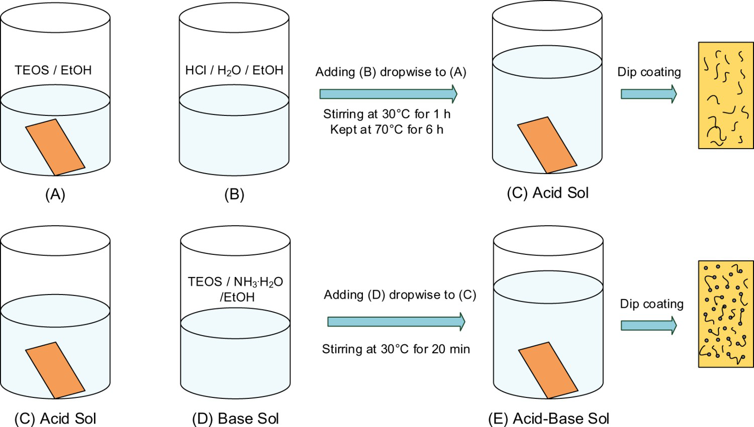
Evaluation experiment
In order to evaluate the performances of coating, the following evaluation experiments were conducted [16,17].
Water vapour experiment: In order to simulate the influence of water vapour, 100 mL of water was placed in a 250 mL beaker. The sample of SiO
x
-coated Kapton substrate was suspended in the upper part of the beaker with a clip and covered with a plastic wrap, and the beaker was heated to 50°C for 2 h. Then, the sample was removed and dried at room temperature. Temperature alternating experiment: To evaluate the ability of the coated samples to resist the environmental temperature change, SiO
x
-coated Kapton substrates were sealed and placed in 80°C oven for 1 h. Then, the substrates were immediately taken into the refrigerator freezer (about −10°C) for 1 h, as a cycle. The substrates were observed microscopically after 5, 10 and 20 cycles, respectively. Bending experiment: Take a 4 cm × 2 cm of SiO
x
-coated Kapton sample, bend the sample at a speed of 30 times min−1 and observe the coating adhesion through a microscope after 500 and 1000 times, respectively.
Atomic oxygen radiation test
According to a previous report [18], the AO resisting ability of samples was characterized by a coaxial ground-based AO simulation device. The energy of AO produced in this device was an average of 5 eV, and the AO flux was 1.48 × 10¹⁶ atoms cm−2 s−1. The samples were irradiated for 5 h, and the mass loss was measured via a microbalance with a precision of 10−5 g [19].
The AO fluence was calculated according to the equation below [20,21]. Where F is total AO fluence (atoms cm−2),
 is mass loss of Kapton H (g), AK is the exposure area of Kapton H (3.14 cm2), ρK is the density of Kapton H (1.42 g cm−2) and EK is the erosion yield of Kapton H (3 × 10⁻²⁴ cm3 atom−1) of Kapton HN.
Film characterization
The optical transmittance of samples before and after AO irradiation was measured by a TU-1901 UV–vis spectrophotometer (Puxi, China). The wettability of samples was measured by a JC2000D1 contact angle analyzer (Zhongchen, China). The surface appearances of samples were studied using a Leica DM2700P microscope. The surface morphologies of Kapton- and SiO x -coated samples before and after AO exposure were investigated by a Hitach S-4800 field emission scanning electron microscope (FE-SEM). The tensile strength and elongation at break of samples were measured with a smart electronic tensile tester at a tensile rate of 10 mm min−1 at ambient temperature. The sample structure was measured by Fourier-transformed infrared spectroscopy (FT-IR 8400S; Shimadzu) using an attenuated total reflectance mode.
Results and discussion
Kapton surface treatment
Changes in the molecular structure of Kapton samples treated by acid–base and APTES were measured by FT-IR spectra. It can be seen from Figure 2 that the characteristic absorption peaks of the samples treated by the NaOH hydrothermal process (0.1 mol L−1 NaOH, 120°C, 1 h) and diluted HCl (0.05 mol L−1 HCl, RT, 30 min) or again treated by the 20% APTES/80% PhMe solvothermal process (70°C, 2 h) are not significantly changed. 1775 cm−1 is the symmetrical stretching vibration peak of two carbonyl groups on the five-membered imine ring in polyimide (Kapton), and 1712 cm−1 is the corresponding asymmetric stretching vibration peak. The C–N stretching vibration of imine ring is located at 1365 cm−1. The peaks at 1495 and 1598 cm−1 can be assigned to the C=C stretching vibrations of benzenoid and quinonoid rings, respectively [22,23].
FT-IR spectra of treated Kapton under different conditions.
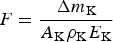
Figure 3 shows the water contact angle of Kapton after surface treatment. The water contact angle on the surface of pristine Kapton is 85° (Figure 3(a)) [24]. After being modified by different treatments, the contact angles are obviously decreased, indicating that hydrophilicity has been improved. The passivation layer on the Kapton surface was removed by alkaline solution, and the polar functional group –COO− was formed, resulting in reduction of the contact angle (52°) (Figure 3(b)) [25]. After solvothermal treatment with APTES/PhMe, the contact angle of Kapton decreased to 41° (Figure 3(c)). The reason is that the siloxane group of APTES was hydrolyzed to a silanol group at room temperature, which increased the hydrophilicity and decreased the water contact angle further [26-28].
Water contact angles of Kapton after surface treatment: (a) pristine Kapton, (b) NaOH + HCl and (c) NaOH + HCl + APTES/PhMe.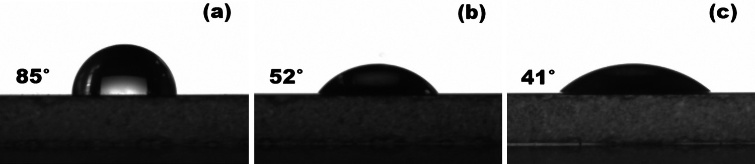
After alkali treatment, it can be seen that the light transmittance of Kapton decreased significantly in the range of 500–800 nm compared with the pristine Kapton (Figure 4). After hydrothermal treatment with a low concentration of NaOH, the passivation layer on the Kapton surface was removed; at the same time, the surface was also etched slightly [29]. The etched surface was microscopically uneven, which may cause diffuse reflection and decrease light transmittance. However, after the solvothermal treatment with ATPES/PhMe for the alkali-treated sample, a film was formed on the sample to make the surface smooth [15]. Therefore, the transmittance curve presented an increasing trend, which was almost consistent with the pristine Kapton.
Transmittance curves of Kapton after surface treatments.
Coating characterization
Figure 5 shows that the coating formed on the Kapton surface contains a large number of wrinkles, which is related to the preparation process. The base and the ATPES-treated Kapton sample were placed in a TEOS/EtOH solution, and a HCl/H2O/EtOH solution was slowly added to form a liquid film on the Kapton surface. When the liquid film gradually solidified, it was found that the wrinkles exhibited on the Kapton surface.
Microscope and SEM pictures of Kapton after acid sol coating: (a) two-dimensional, (b) three-dimensional and (c) SEM.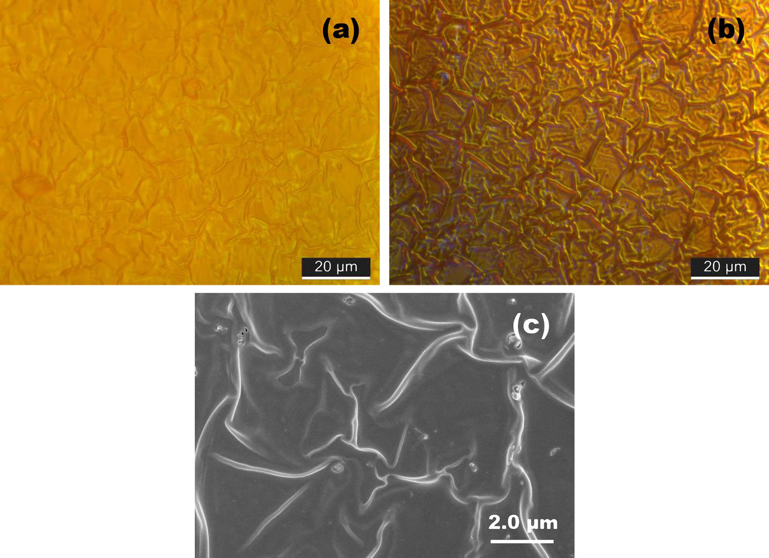
In the above preparation process, if the HCl catalyst is replaced with NH3·H2O, as shown in Figure 6, the morphologies of the coatings changed greatly. The Kapton surface is piled with uneven particles. The reason is presumed to the mechanism of sol–gel formation under base catalytic conditions. The sol polysilicate grows as a monomer cluster to form a high-branched polymer cluster and eventually tends to agglomeration granular structure [30,31].
Microscope pictures of Kapton after base sol coating: (a) two-dimensional and (b) three-dimensional.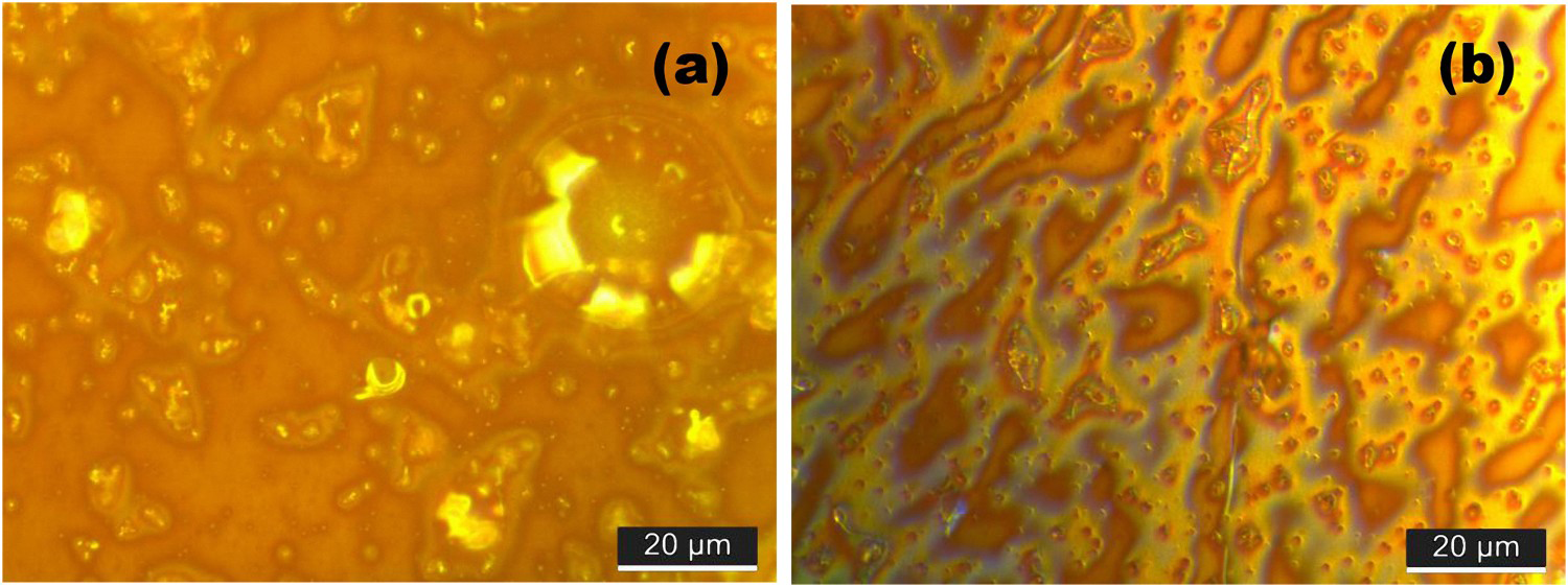
Figure 7(a,b) shows that the coating prepared by the acid–base mixed sols was almost uniform and dense, and a small amount of large particles aggregated on the surface. It can be seen from Figure 7(c) that the coating consisted of continuous tiny particles different from the single acid or base sol. The results indicated that the acid–base mixed sol effectively inhibited particle aggregation, which was in good agreement with literatures [32,33].
Microscope and SEM pictures of Kapton after acid–base mixed sol coating: (a) two-dimensional, (b) three-dimensional and (c) SEM.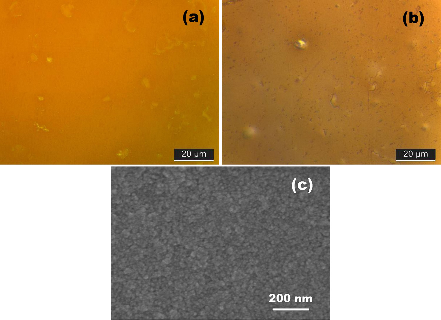
Tensile strength and elongation at break of Kapton under different treatment conditions.
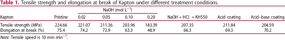
Note: Tensile speed is 10 mm min−1.
It can be seen from Table 1 that the NaOH hydrothermal treatment has a certain effect on the Kapton. With the increase of NaOH concentration, the etching intensity increases, and the tensile strength and elongation at break show a downward trend [34]. However, the low concentration of NaOH does not cause a large damage to the Kapton substrates. So, the NaOH concentration being controlled within 0.1 mol L−1, a better surface treatment effect can be obtained. After the hydrothermal treatment with the low concentration of NaOH, the samples to be further treated by the APTES/PhMe solvothermal process, the tensile strength and elongation at break were all decreased again. It may be related to the toluene swelling of Kapton matrix [35]. However, after an acid silica sol formed a coating on the Kapton surface, the tensile strength and elongation at break changed from decreasing to increasing. It is presumed to be the wrinkle coating, which enhances the tensile resistance of the sample. The same phenomenon also occurs in the acid–base mixed coating, and the elongation at break of the sample is improved.
Evaluation experiment
Figure 8(a) shows a SiO
x
coating prepared on the surface of Kapton using an aged SiO2 sol. The surface treatment of sample (Figure 8(a)) is also different from that of this paper (Figure 8(b–d)). The solvent used in the APTES solvothermal process is not toluene but ethanol. The surface morphology of the coating is uniform and dense. However, when the ambient humidity is relatively high, or there is moisture, the coating may be cracked or even peeled off (Figure 8(a)). The inorganic SiO
x
coating adsorbs moisture, weakening its adhesion to the Kapton matrix, and is easy to fall off [36].
Microscope pictures of acid sol-coated samples after the evaluation experiments: (a,b) water vapour, (c) temperature alternating and (d) bending.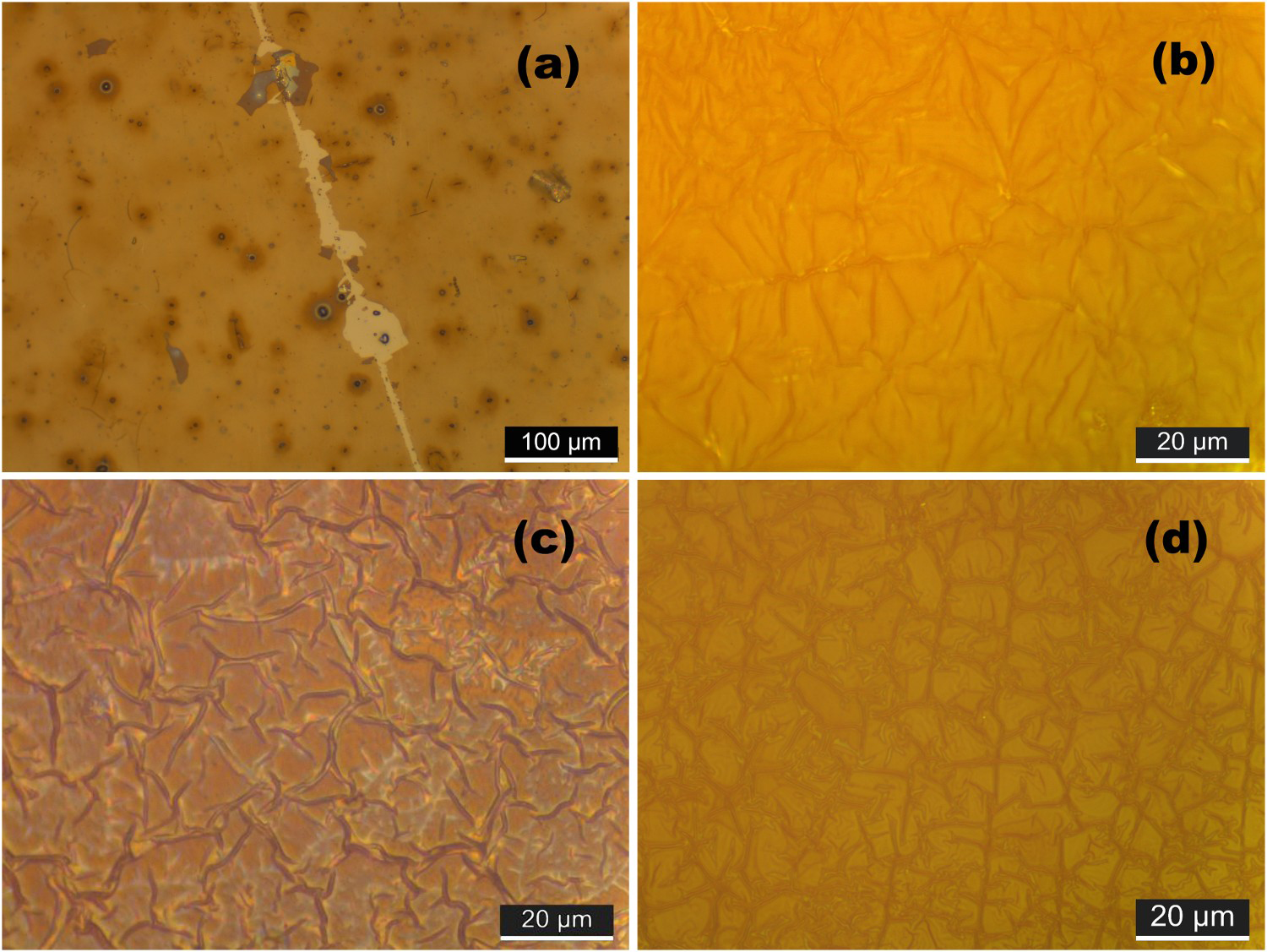
In this paper, the solvothermal medium is changed from ethanol to toluene, and the modified Kapton film is directly placed in a TEOS ethanol solution and always present in the solution, until the solution system forming a sol, then pulled it out. Three evaluation tests of water vapour, temperature alternating and bending were used to study the interface bonding between the coating and the Kapton matrix. After 50°C for 2 h water vapour test, from 80°C to −10°C cold and heat alternating 20 cycles and bending 1000 times, it can be seen from Figure 8(b–d) that the coating did not appear shedding or cracking, showing that the coating is firmly bonded to the substrate. According to the test results, it is presumed that the bonding process of coating and substrate is as follows (Figure 9(a–d)): the –NH2 group of APTES is bonded to the –COOH group of the acid–base-treated Kapton in the toluene solvothermal environment, followed by the respective –OR group of APTES, and TEOS is hydrolyzed and condensed to form a Si–O–Si bond in the ethanol solution. The existence of wrinkles relieves and releases the stress between the coating and the substrate, thereby avoiding the situation of stress cracking.
Schematic illustration of the bonding process of SiO
x
coating and Kapton matrix.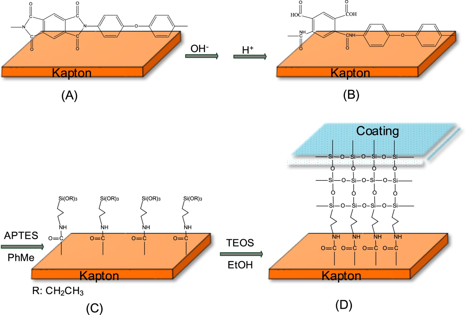
AO exposure
After 2.66 × 10²⁰ atom cm−2 AO fluence irradiation, the surface morphology and transmittance of Kapton samples have changed greatly. Before the AO irradiation, the pristine Kapton had a smooth, uniform surface and a small number of nano-protrusions (Figure 10(a)). After irradiation, the surface became rough and dull, showing a ‘carpet-like’ morphology (Figure 10(b)), indicating that the sample was severely attacked by atomic oxygen [37-39]. On the contrary, the coated samples were prepared by a sol forming process, either acid sol or acid–base mixed sol, and did not appear obvious defects, having a good resistance to atomic oxygen. Only the particles became larger and sharper, which was caused by the further oxidation in the AO environment (Figure 10(d,f)) [40].
SEM images of samples before and after AO irradiation: (a) pristine Kapton, (c) acid sol-coated Kapton, (e) acid–base mixed sol-coated Kapton and (b,d,f) after AO irradiation.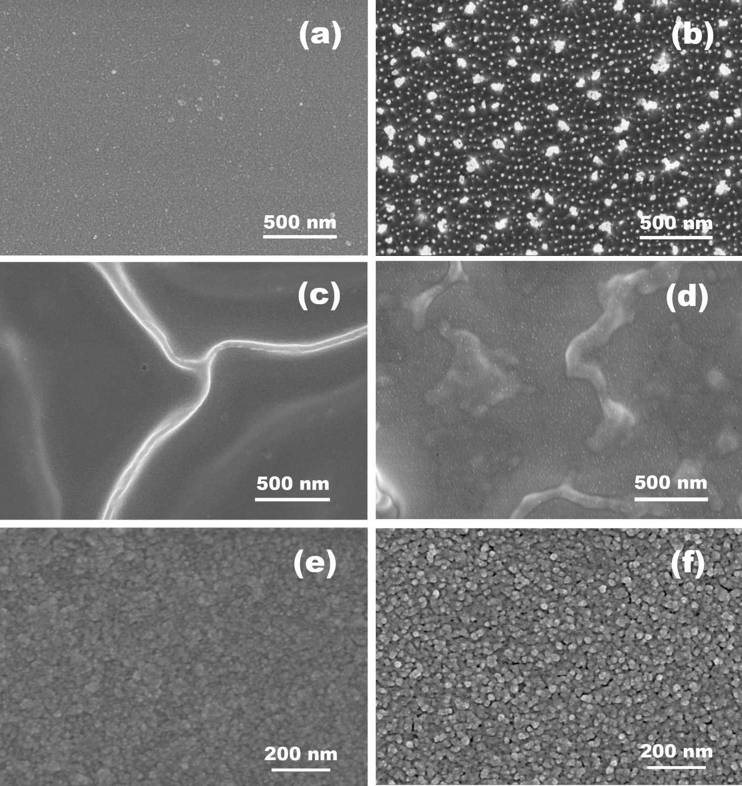
The transmittance curves of samples can also indirectly reflect the degree of AO erosion. It can be seen from Figure 11 that the transmittance of pristine Kapton decreased sharply after AO irradiation. Under the same conditions, the acid sol-coated Kapton only decreased slightly, and the acid–base mixed sol-coated Kapton maintained a high transmission rate.
Transmittance curves of Kapton samples before and after AO irradiation.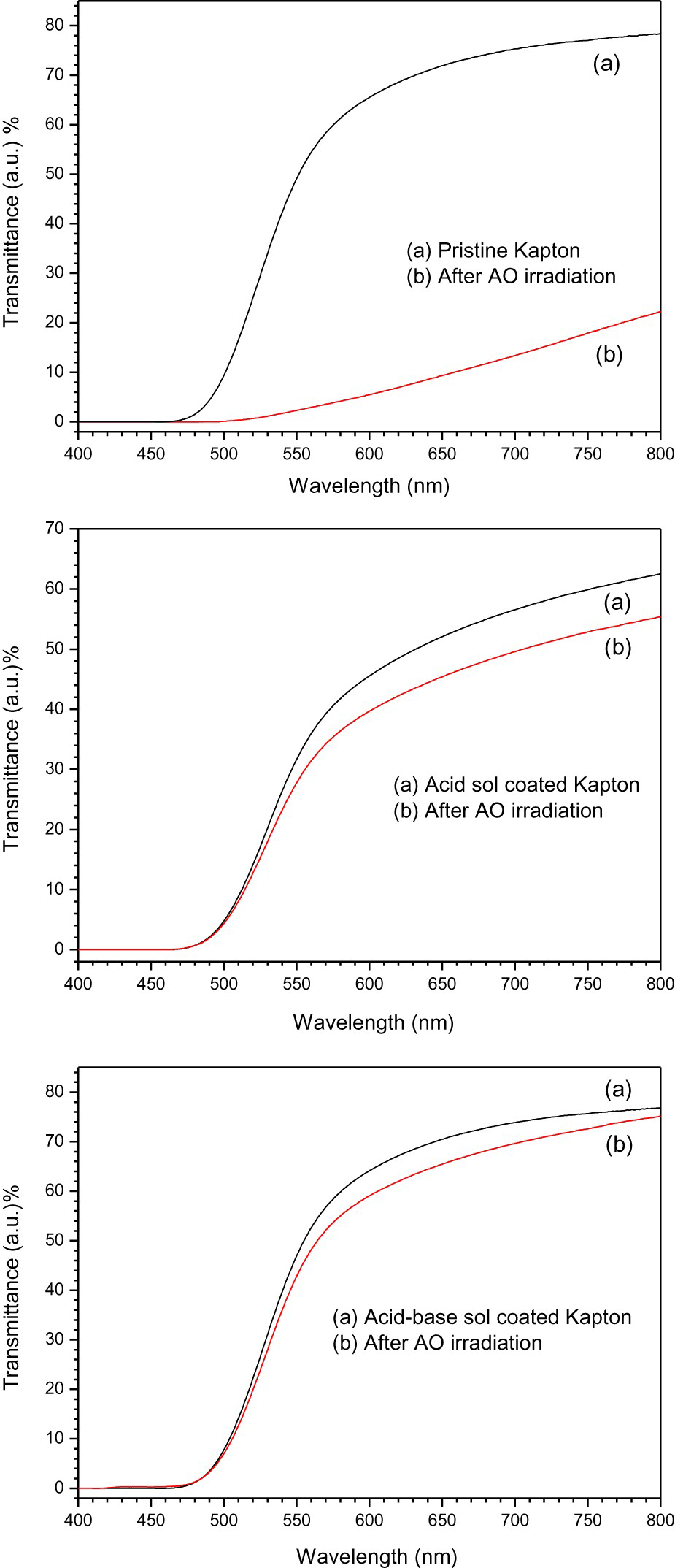
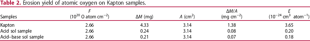
Erosion yield of atomic oxygen on Kapton samples.
Conclusion
In this work, a coating with micro–nanometre wrinkles is obtained based on the study of preparation procedure of SiO x coating on the surface of Kapton. Hydrothermal treatment with 0.1 mol L−1 NaOH can effectively remove the passivation layer of Kapton, and the ATPES/PhMe solvothermal process can improve the surface wettability. The water contact angle is reduced from 85° to 41°. The coating is firmly bonded to the Kapton structure and can resist the influence of environmental factors such as water vapour and temperature change. AO exposure experimental results demonstrated that the prepared coatings can improve AO resistance ability of Kapton remarkably.
Footnotes
Disclosure statement
No potential conflict of interest was reported by the author(s).