
Abstract
The heat dissipation efficiency of the radiator is of great significance to the reliability of the power transformer system. However, traditional coatings on the radiator are designed to improve the corrosion resistance of radiators, which usually have a lower thermal conductivity. In this work, the thermal properties of graphene-doped coating have been studied using a combination of electrical and optical method. It has shown about a 15% improvement in the thermal conductivity compared to the traditional anticorrosive coatings. It will be shown that the graphene can not only spread more heat to enable the sample to reach the steady state more quickly but also enhance the heat radiation to lower the temperature. It provides a simple and effective way to accelerate the heat spread of radiators and thus lower the system temperature.
Keywords
Introduction
Power transformers are essential parts of equipment in high-voltage substations. There is currently interest in improving the long-term stability of this equipment [1-3]. The heat dissipation of power transformers is an important factor affecting their performance. Therefore, a radiator is used to accelerate the heat spread aiming to lower the temperature. In order to resist the corrosion and improve the lifetime of radiators, a coating is necessary. The traditional coating is based on aqueous inorganic silicate primer [4] with a poor thermal conductivity that needs to be further improved.
Graphene has drawn interest in recent years owing to the many unique properties, such as the high thermal conductivity, the stable chemical inertness, and impermeability to ion diffusion [5-8]. Graphene coating has been applied to maintain the shape and boost the strength of the coating, making the coating more resistant to fatigue [9]. Graphene-doped coating can also greatly improve the corrosion resistance using the aqueous cathodic electrophoretic deposition (EPD) [10,11]. However, studies in the thermal conductivity improvement of the graphene-doped coating are still lack compared to those in the mechanical properties [12].
In this work, we identified the role of the graphene in a coating. Graphene has been added into the coating and its thermal conductivity has been demonstrated with a comparison to the traditional coating. The thermal conductivity of the radiator of a power transformer to the ambient surroundings can be evaluated from its thermal resistance [13,14]. The thermal resistance of a P-N junction to the ambient environment, Rth(J-A)
is given by
Experiment details
Examples of power transformer materials in our experiment included steel plate of the same composition and same thickness compared to a typical radiator in power transformers. The base material was approximately 8 cm × 8 cm. To simulate the thermal conductivity of the radiator of a power transformer, one side of the steel plate was not sprayed with coating, and the other side was sprayed with coating.
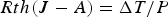
The procedure for spraying the graphene composite coating included undercoat selection, graphene selection, composite coating preparation, and spraying. The detail procedure is shown in Figure 1. The base material for graphene composite coating was a resin, which is a commonly material in traditional anticorrosion coatings. A dispersant was added to the resin to dissolve inorganic materials. Then multilayered graphene (<7 layer) was added into the coating and was fully mixed and stirred to form the graphene-doped coating. We used zirconium pearl to disperse the coating, which generated a mass of bubbles. The composite coating was left to stand for one hour to eliminate bubbles. The resulting composite coating was sprayed onto steel plate (base material) with a spray gun. Finally, the sample was dried for 1 h to form coating samples.
The procedure of spraying graphene composite coating.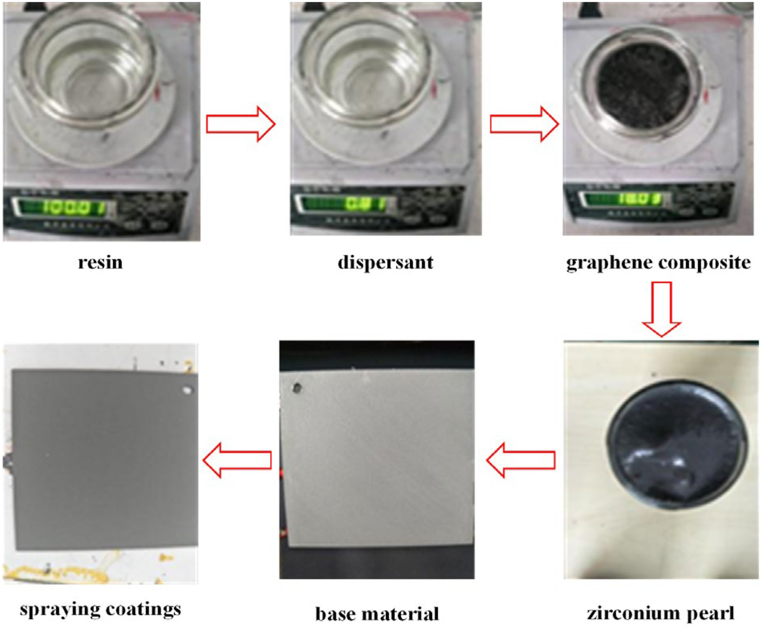
A diode was used to heat the sample and monitor the temperature transient. The measurement procedure was as follows: (1) measure the temperature coefficient of the diode; (2) apply a constant power to the diode to heat the sample until reaching the steady state. (3) Cut down the power and immediately switch the diode to the measuring mode (under a constant current) to measure the voltage transient and then the temperature transient can be calculated using a combination of the temperature coefficient and the voltage transient. (4) Use the structure function method to analyse the temperature transient and acquire the differential structure function [14,16], that is, Figure 2.
Thermal resistance result of a typical structure measured in this work.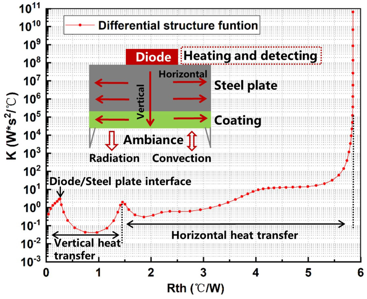
Owing to the much larger horizontal area compared to the vertical structure, the horizontal heat transfer process could be seen as an independent part in the heat transfer path with a long time constant. A typical differential structure function of the structure measured in this work has been shown in Figure 2.
The coating is the only variable factor in the experimental so that its influence on the thermal conductivities of the structure could be compared.
Results and discussion
LWT is a common coating based on an aqueous inorganic silicate primer, and LWT-M650 is an aqueous acrylic resin, which is a traditional anticorrosion coating. Thermal resistances of both of them have been tested compared to the graphene coating with various proportions as shown in Figure 3.
(a) Thermal resistance measurements of different proportions of graphene composite coating. (b) Extracted total thermal resistances.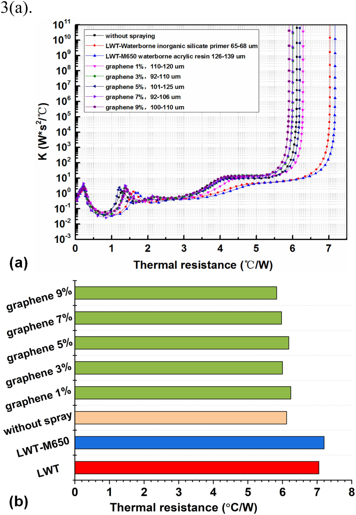
Figure 3(a) is the calculated differential structure function [14]. The change in the total thermal resistance has been regarded as the influence of the coating because the coating is the only variable condition as we mentioned before. Figure 3(b) shows the change extracted from Figure 3(a).
The total thermal resistance of LWT-M650 and LWT are 7.18 and 7.05°C/W, respectively. The graphene-doped coatings with proportions from 1% to 9% lead to significantly lower thermal resistances of 6.24, 6.00, 6.18, 5.97, and 5.83°C/W, respectively, indicating a 15.3% lower highest temperature could be achieved at the proportion of 9%. Figure 4 shows the relationship between the proportions of graphene in the coating and the decreased thermal resistance extracted from Figure 3. In general, the larger the proportion of graphene in the composite coating, the higher thermal conductivity could be acquired.
Extracted relationship between the proportions of graphene in the coating and the decreased thermal resistance.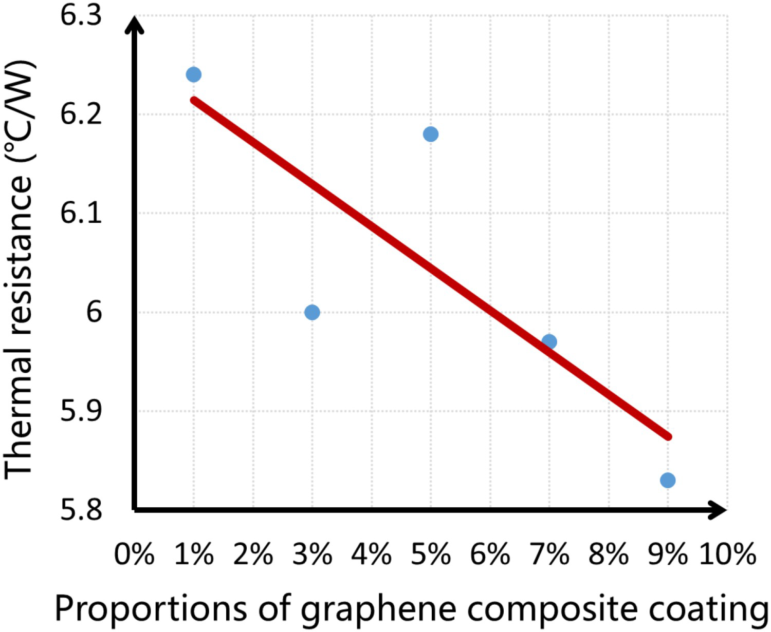
IR measurements have been carried out using the FLIR (FLIR Systems, Inc) System SC5700 [16] to demonstrate the mechanism of graphene-doped coating accelerated the heat dissipation. Samples were put in a platform with a constant temperature. The sprayed side was side up as shown in Figure 5.
Infrared measurement diagram.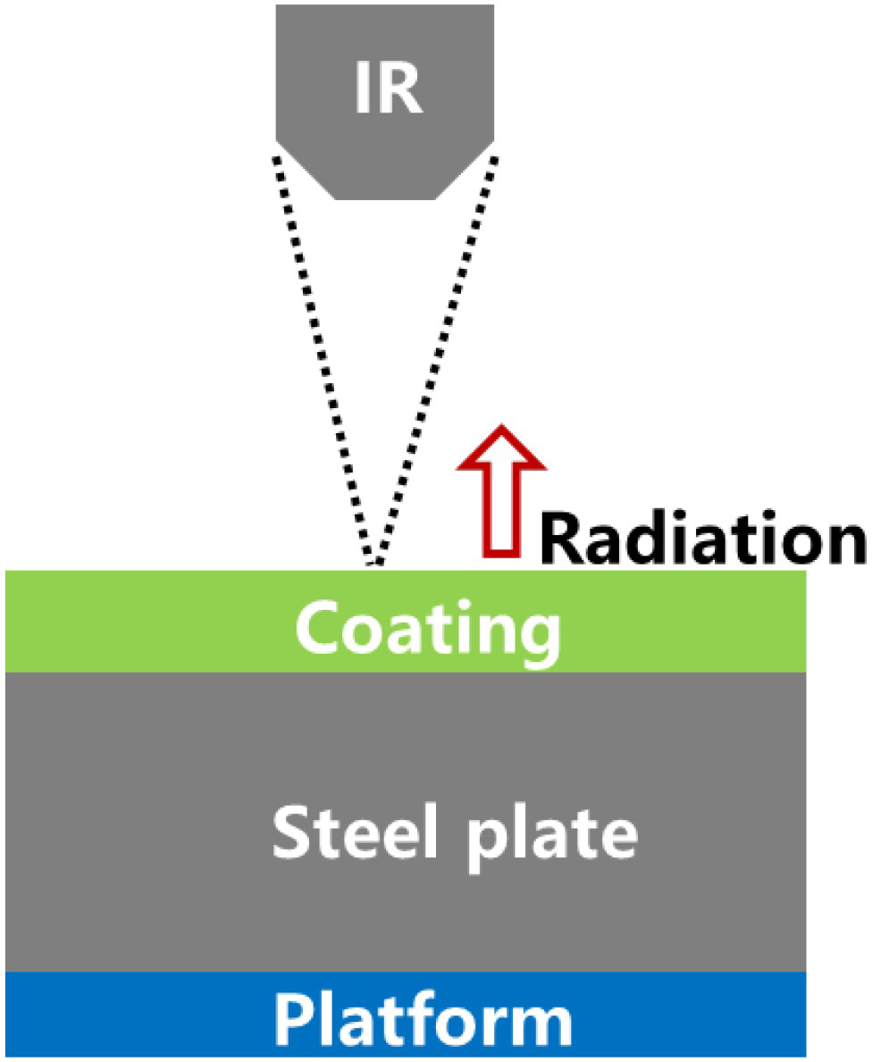
Measured temperatures have been shown in Figure 6. The graphene-doped coatings have shown infrared emittances nearly 1, which are much higher than traditional anticorrosion coatings. Thus, graphene-doped coatings could improve the total thermal conductivity of the structure by enhancing the heat radiation and thus lead to a higher cooling efficiency compared to the traditional coating.
Infrared emittance measurements.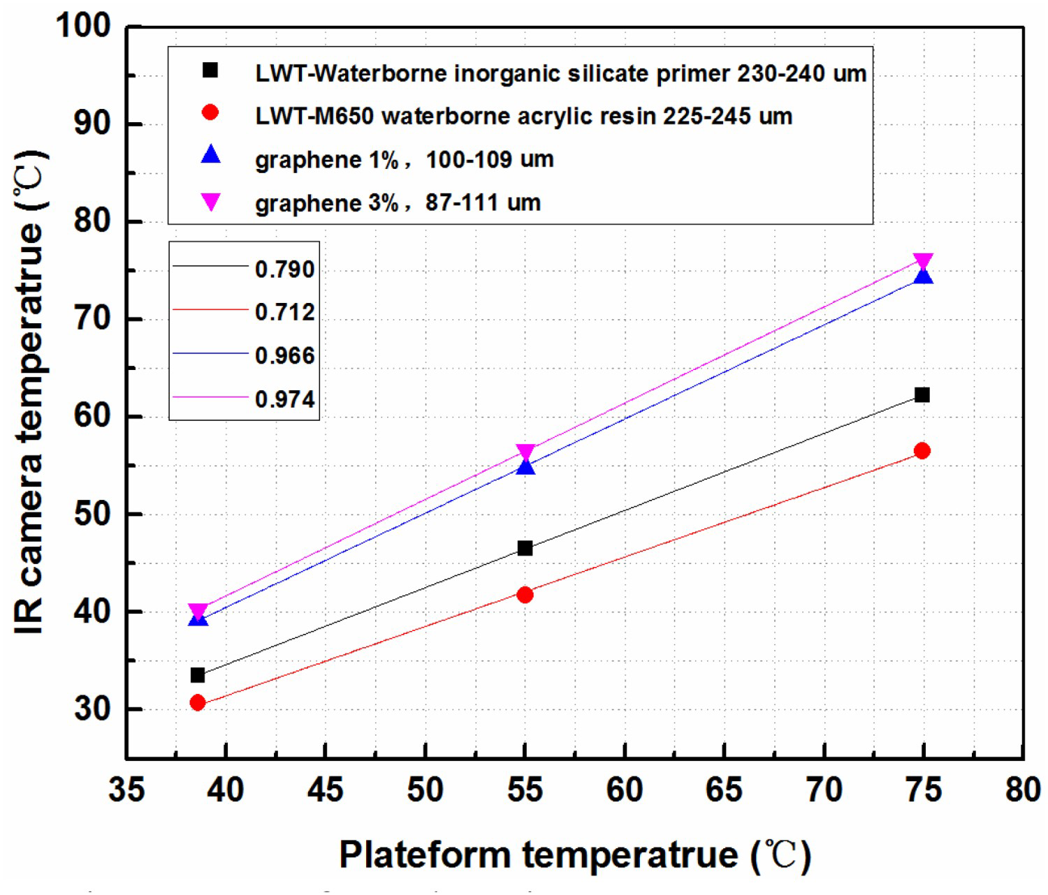
In addition, the increase in the infrared emissivity could also improve the accuracy when using the IR system to measure the surface temperature of the plate.
Conclusion
We have sprayed a graphene composite coating onto samples to improve their thermal conductivity for applications in power transformers. This graphene-doped coating decreased the temperature by improving the horizontal heat transfer process and increasing the heat radiation. A 15% improvement of thermal conductivity has been achieved for the structure tested in this work. The graphene-doped coating is a promising way to benefit the thermal properties of the power transformer system.
Footnotes
Acknowledgements
This research was supported by the Key Technology and Equipment for Large-Scale and Safe Charging of Electric Vehicle under Grant No. 2016YFB0101901; the National key research and development program of science and technology of china under Grant No. KZ201710005008.
Disclosure statement
No potential conflict of interest was reported by the author(s).