
Abstract
In this study, monolayer TiN and multilayer TiN/Ti coatings involving different modulation ratios were deposited on Ti–6Al–4V substrate. Ti interlayers in the multilayer TiN/Ti coatings were prepared under gradient negative bias of –800, –600, and –400 V, with corresponding durations of 2, 2, and 1 min. Mechanical properties and crack' s resistance of the coatings were explored. Damage morphology of coating cross-section was characterized by the focused ion beam (FIB) method. Finite element modelling was used to analyse the stress field. Multilayer TiN/Ti coatings show better impact resistance than monolayer TiN coating. Tensile stress decrease with the increase of interfaces. Gradient bias Ti interlayers restrain crack propagation by cracks deflection and branch. Erosion resistance was evaluated by sand erosion test. Crack propagation and connection account for the coatings failure: the deeper the crack propagation, the higher the erosion rate.
Keywords
Introduction
Sand erosion is a common material failure mode that severely damages aeroengine blades, thereby reducing the service life and aerodynamic efficiency of aeroengine [1-3]. As surface engineering technology developed, depositing a protective coating on substrates emerged as an effective method for enhancing the anti-erosion performance of compressor blades. To date, TiN-based coatings are the most widely employed industrial erosion resistance coatings for aeroengines [4,5]. However, TiN monolayer coating exhibits poor anti-erosion resistance at high erosion angle for brittle fracture. It is found that multilayer TiN-based coatings are believed to have higher fracture resistance than TiN monolayer coating due to the lower elastic modulus of Ti layer, crack deflection, and crack-tip shielding by the interfaces [6,7]. During ion plating, ions bombard the substrate and the surface of coating continuously under the acceleration of the negative bias electrical field. Negative bias is a crucial parameter that determines the value of ions bombardment energy since high ion energies may cause ion sputtering whereas low ion energies will lead to deposition [8]. Highly energetic ion sputtering was proved as an effective method for clearing the loose texture, enhancing diffusion, and creating graded interfaces [9,10]. Therefore, TiN/Ti coatings with Ti interlayer deposited under gradient bias should have a higher adhesion between interlayers and toughness compared to traditional TiN/Ti coatings. However, there are little works that focus on the effect of Ti ion sputtering on the failure mechanism of gradient bias TiN/Ti coatings.
Numerous studies investigate the damage and failure mechanism of TiN/Ti coatings by erosion test and nano-impact technique [11-15]. The drawback of the erosion test is that the quantity of sand particles is hard to measure and their trajectories are different, in which erosion angle and velocity of the sand particles cannot be controlled accurately. The impact angle and velocity in the nano-impact test are more accurate than the erosion test. While the impact load applied in the nano-impact test is less than the impact energy of particles in the actual erosion. Compared to the previously mentioned tests, single-particle test has a higher impact energy and accuracy. Thus, the understanding of internal crack propagation of coatings with different modulation ratios on the erosion resistance at a high incident angle is still not clear.
It has been established that modulation ratio and layer number of coating are important factors affecting its mechanical properties and erosion resistance. Numerous studies have revealed that the hardness, yield strength, and bonding strength of the TiN/Ti multilayer films increases with the increasing of multilayers [9,16]. While the erosion resistance of the TiN/Ti multilayer coatings decreases as the layers number increases due to the increase of vulnerable regions with high tensile stress at TiN layers [10]. Obviously, there are conflict results in the literature regarding the effects of the modulation ratio on the mechanical property and erosion resistance of the TiN/Ti coatings.
In this study, differently modulated gradient bias TiN/Ti coatings with each TiN interlayer deposition duration of 15, 30, and 60 min were prepared and their microstructure, phase composition, elastic modulus, hardness, and erosion resistance were characterized and compared with TiN monolayer coatings. Single-particle impact experiment was performed to investigate the inhibition effect of modulation ratio on the crack propagation. Further, cross-sections of the coatings were prepared by the focused ion beam (FIB) technique and characterized by scanning electron microscopy (SEM). The stress field and dynamic response were investigated by FE modelling.
Materials and methods
Coating deposition
The coatings were achieved on the Ti–6Al–4V alloy substrate by filtered cathodic vacuum arc deposition (FCVAD). The substrate was first polished to less than 0.02 Ra, followed by cleaning with acetone in an ultrasonic cleaner for 15 min, and drying under an N2 flow. To improve the adhesion between the coatings and substrates, ion implantation (Ti ion) was performed with a vacuum degree of 1.0 × 10⁻³ Pa, a voltage of 8 KV, and an ion beam of 5 mA. Ti layer was then deposited as a transition layer with a bias voltage of –250 V. TiN and gradient bias Ti layers were then alternately deposited on the transition layer. The TiN layer was deposited at an N2 flow rate of 9 sccm, under a negative bias voltage of –250 V and an arc current of 110 A. Gradient bias Ti layers was prepared under negative voltages of –800, –600, and –400 V, with corresponding times of 2, 2, and 1 min. Ti interlayer with identical parameters was deposited every 15, 30, and 60 min, henceforth referred to as S15, S30, and S60. For comparison, coatings without a gradient bias Ti layer (referred to as S) in the TiN multilayer were also deposited, and the thickness of each coating was limited to approximately 20 μm.
Microstructure and mechanical properties characterization
The cross-sections and surface micrographs of the coatings were characterized by SEM (MIRA3, TESCAN, Czech). In addition, wide-angle XRD patterns of the samples were recorded by an X-ray diffractometer (D8 Advance, Bruker, Germany) operating at 40 mA and 40 kV with Cu Kα radiation (scanning range 5–85°, step size 2°, scanning speed 8° min−1). Further, nanoindentation was conducted to obtain the elastic modulus and hardness of the coatings by nano-indenter (TI950 TriboIndenter system) with a Berkovich indenter. The nanoindentation tests were performed under the load-controlled mode with a maximum load of 100 mN and a loading and unloading rate of 3.5 mN s−1. During the test, the indentation depth was controlled to stay within 1/10 of the coating thickness to reduce the influence of the substrate. For each sample, the elastic modulus and hardness of the coating were calculated from the average of at least six individual indentations according to the Oliver–Pharr method. Besides, H3/E2 ratio was calculated as the index to evaluate the crack resistance of the coatings, which has been mentioned in many researches [11,17].
Single particle impact tests
To evaluate the toughness and explore the effect of modulation ratio on the crack resistance of the gradient bias TiN/Ti coatings, single solid particle impact tests were conducted using an air gun experimental system. The system accelerates the ball-shaped particles to impact the coatings at set erosion velocities and angles, and the details of the equipment are provided in a previous study [18]. The particles used in the tests were GCR15 spherical particles of approximately 0.8 mm diameter. Single-particle impact test was carried out under the impact velocity of 130 m s−1 and a high impact angle of 90°, at which coatings are more vulnerable. Surface microtopography of the impacted areas after tests were observed by SEM. The cross-sectional micromorphology of coatings was processed by FIB, which protected the microscopic cracks better compared with the traditional polishing method.
Sand erosion experiments
Sand erosion experiments were conducted to evaluate the erosion resistance of the coatings by gas blast tester based on specifications in the ASTM standard G76 [3,19,20]. The sand comprised angular quartz particles with sizes ranging between 0 and 200 μm. As for hard ceramic coatings, the TiN coatings are most vulnerable under high erosion angles. To determine the erosion resistance of the coatings in adverse conditions, the erosion angle, sand feed rate, and erosion velocity were set to 90°, 6.4 g min−1, and 130 m s−1, respectively, during the tests. The distance between the samples and the outlet of the nozzle was 20 mm, with the mass loss rate employed as an erosion resistance index. For each sample, the mass loss rate was calculated from the average of five measurements, while the macro-morphology of the erosion scar was characterized by optical microscopy (OLYMPUS SZ61).
FE modelling
Material parameters in the FE modelling [21].
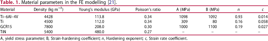
A, yield stress parameter; B, Strain-hardening coefficient; n, Hardening exponent; c, Strain rate coefficient.
Results and discussion
Microstructural and mechanical properties of the coatings
The cross-section microstructures of the coatings from the SEM observations are displayed in Figure 1. All coatings are tightly deposited on the substrate, without cracking or peeling between layers. Typical multilayer structure with interfaces is shown in Figure 1(a–c), with a dark layer representing the TiN layer and a light layer representing gradient bias Ti layer. For the S15, S30, S60, and S coatings, the total thickness of the multilayers was approximately 18.13, 19.85, 21.92, and 22.23 μm, respectively. Evidently, the total thickness of the coating decreased as the TiN interlayer deposition duration reduced. Because the loose TiN texture would be eliminated by Ti ion sputtering during the deposition, the thickness of the coatings decreased with the increasing of gradient bias Ti layers [22,23]. Hence, the S coating is the thickest, while the S15 coating is the thinnest. The Ti interlayers in S15, S30, and S60 were almost of identical thickness, displaying graded interfaces with the TiN interlayer. The graded interfaces were formed because the Ti ions were introduced into the TiN layer at high speeds under high negative bias voltages. This enhanced Ti ion diffusion and improved the adhesion of the Ti sputtering and TiN interlayers [24].
SEM morphology of coatings section: (a) S15, (b) S30, (c) S60, (d) S.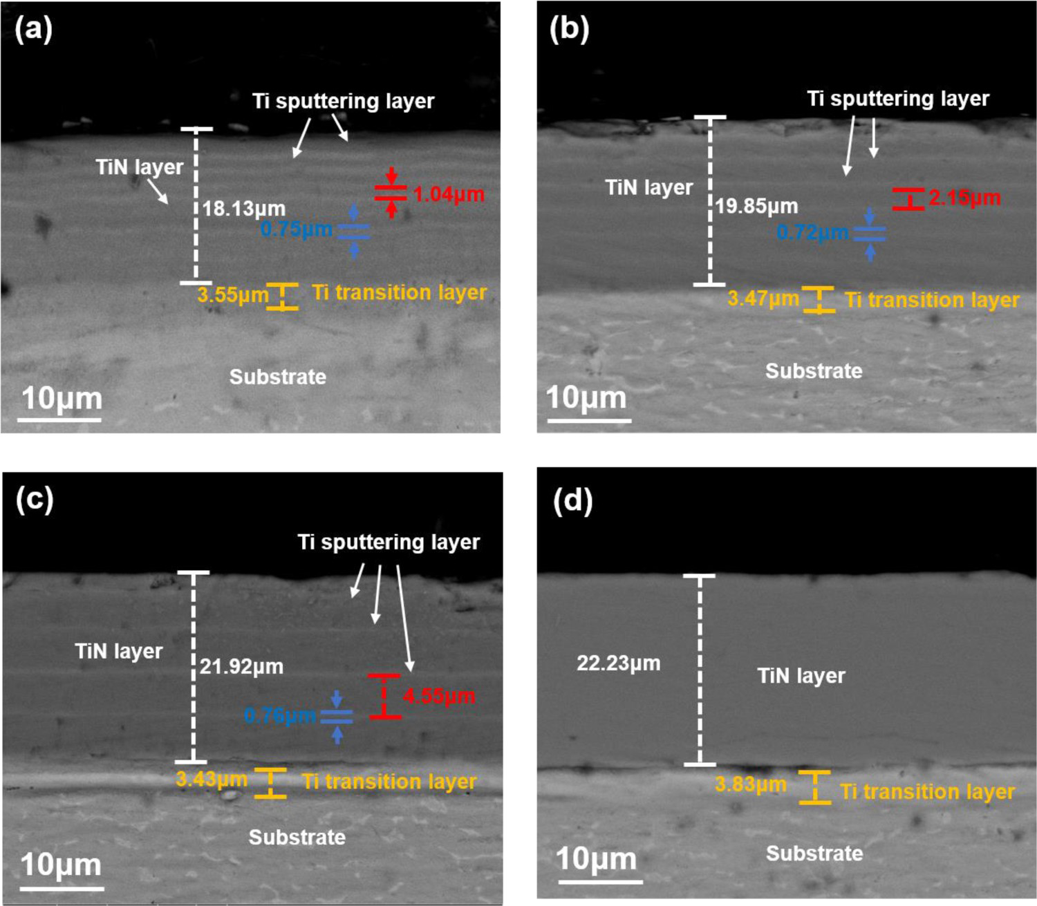
The phase composition of the coatings from X-ray diffraction is displayed in Figure 4. The patterns for the S30, S60, and S coatings exhibit the peaks that indexed to the TiN (JCPDS 38-1420). These peaks (for the S30, S60, and S coatings) are sharp and intense, indicating high crystallinity and purity of the products. The most prominent peaks for the S30, S60, and S coatings correspond to the (111) plane of the cubic TiN. While, the most evident peaks of the S15 coating correspond to the Ti2N (111) plane, indicating that the Ti2N phase exists as a secondary phase in the S15 coating. The reason account for the formation of Ti2N phase is that Ti ions transfer kinetic energy to the substrate, thereby increasing the substrate temperature. In addition, the Ti ions exceed the N ions at the interface of the TiN interlayer and Ti layer because of the Ti sputtering. High substrate temperatures and high Ti ion concentrations led to the formation of Ti2N phase [25-27] (Figure 2).
XRD and corresponding phase constituent analysis of coatings.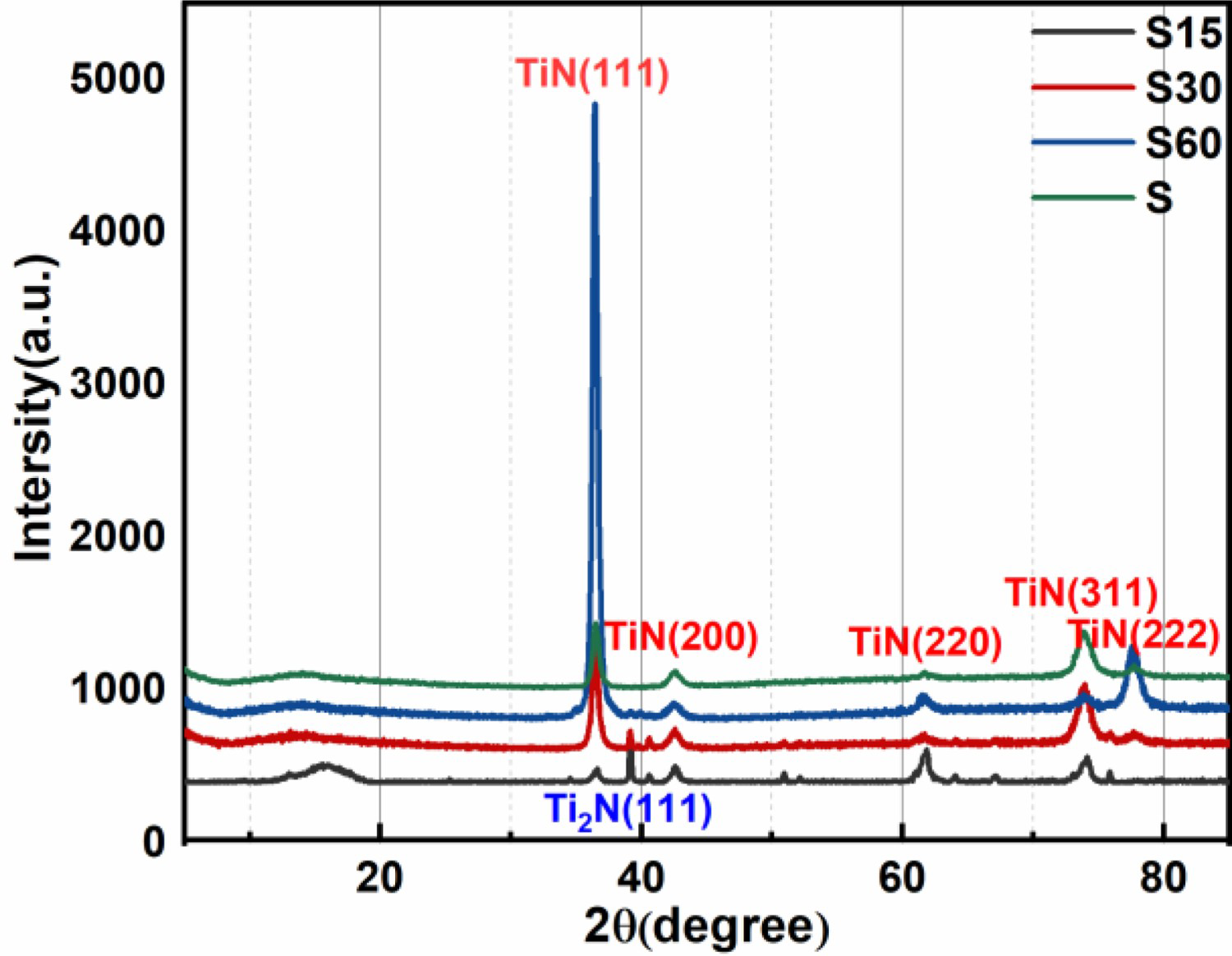
The mechanical properties of the coatings characterized by nanoindentation are displayed in Figure 3. The hardness of the S15, S30, S60, and S coatings were 20.71 ± 0.55, 21.47 ± 0.33, 15.78 ± 0.39, and 33.71 ± 0.35 Gpa, with the corresponding elastic moduli of 184.21 ± 5.75, 148.52 ± 1.29, 110.75 ± 4.09, and 352.48 ± 19.99 Gpa. It can be observed that the hardness and elastic modulus of the S coating are higher than those of the S15, S30, and S60 coatings, which is consistent with previous studies [22,28,29]. This is because gradient bias Ti layer as ductile material layer would decrease the hardness compared with the TiN monolayer coating [30]. Among the TiN/Ti multilayer coatings, the S30 coating shows the highest hardness, followed by the S15 coating, and S60 coating displayed the lowest hardness. This is explained by TiN/Ti alternate structure suppressed dislocation movement inside the coating, owing to the difference in the lattice constant and elastic modulus between Ti and TiN [16,23,24], thereby producing coatings with higher pressure deformation resistance. The plugging effect of TiN/Ti alternating structure on dislocations increases with the increase of the number of cycles, thus the hardness of S30 coating is higher than that of the S60 coating. While, the hardness of the S15 coating is lower than that of the S30 coating. TiN interlayer in the S15 was so thin that the indenter may penetrate it into softer Ti interlayer in the nanoindentation test, which is the main reason for the S15 sample hardness drop.
Hardness and elastic modulus of the coatings.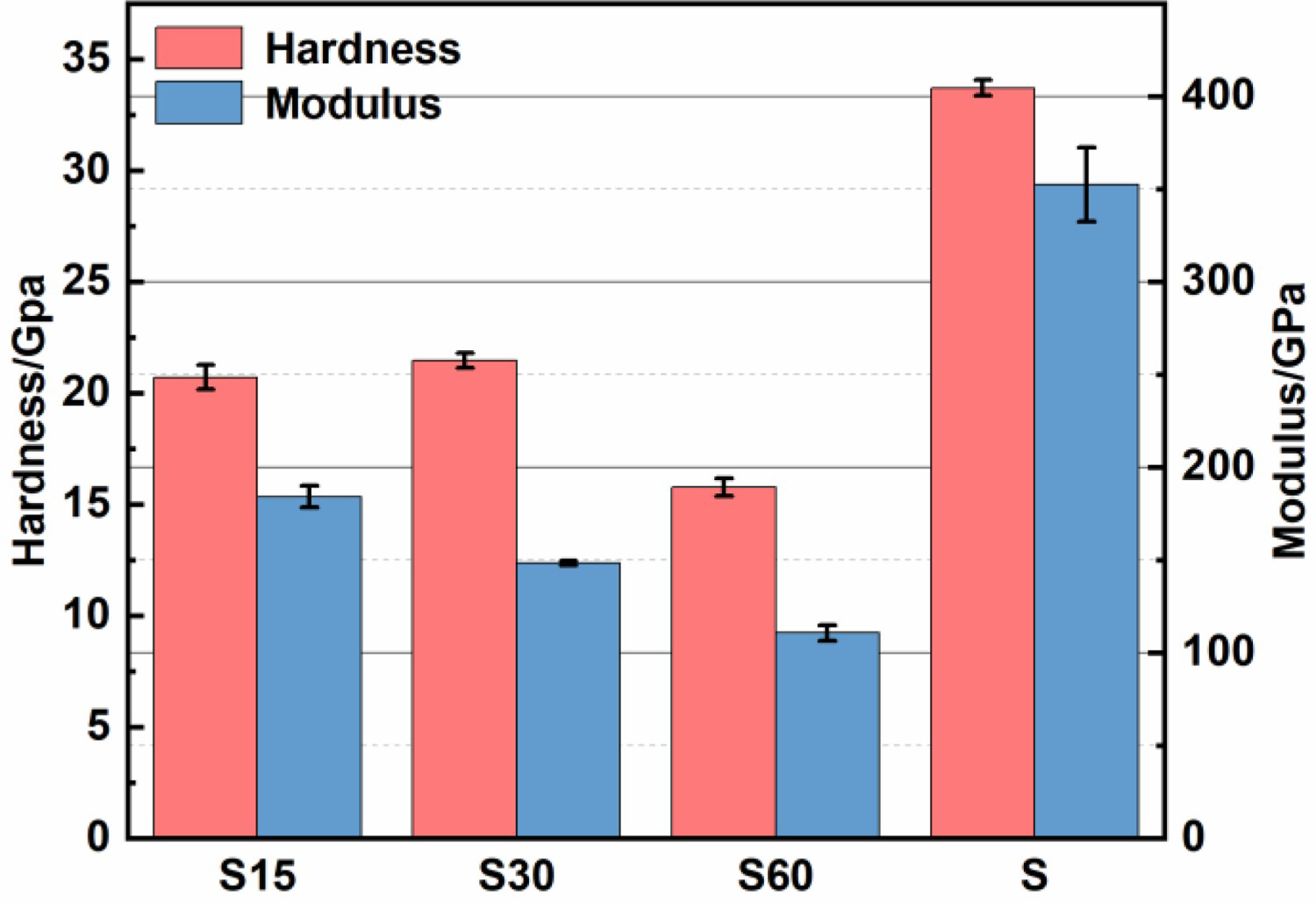
The H3/E2 ratio as a fracture resistance index for the coatings is depicted in Figure 4 [10,17]. The S30 coating shows the highest H3/E2 ratio among the coatings, followed by the S60 and S coating. The H3/E2 ratios of the S and S60 coating were almost similar and both slightly higher than that of the S15 coating.
H3/E2 ratio of the coatings.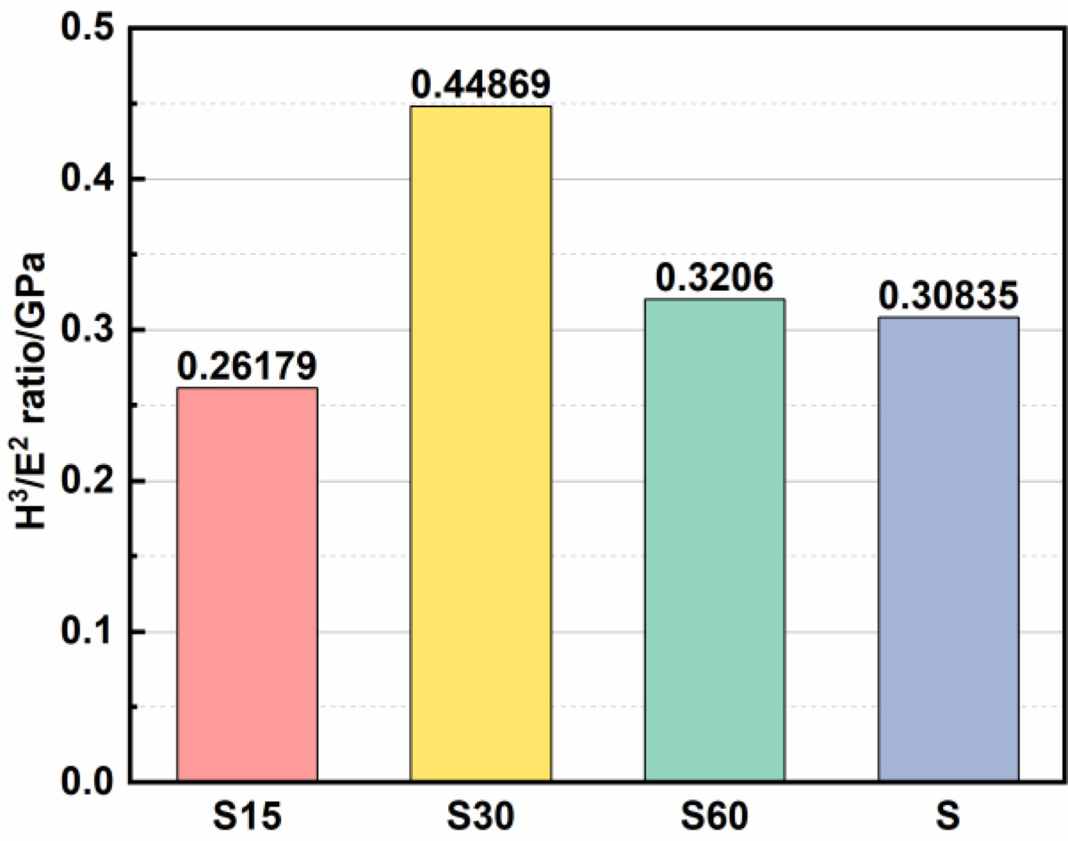
Damage mechanism of the coatings
In order to evaluate the crack resistance and investigate the damage mechanism of coatings, single-particle impact test was performed. The morphologies of the single-particle impact zone characterized by SEM are shown in Figure 5. For all coatings, significant plastic deformation is observed, creating spherical pits on the surface of the coatings, with circular cracks distributed around these impact pits. In addition, radial cracks are also present along the edges of the pits. Both S15 and S30 coatings show high ductility without obvious peeling off. Meanwhile, the crack density of the S15 coating is higher than that of the S30 coatings. Clearly, severe fragmentation along the ring cracks was observed in S60 and S coatings.
SEM morphologies of the single particle impact zone at the speed of 130 m s−1 and erode angle of 45°: (a) S15, (b) S30, (c) S60, (d) S.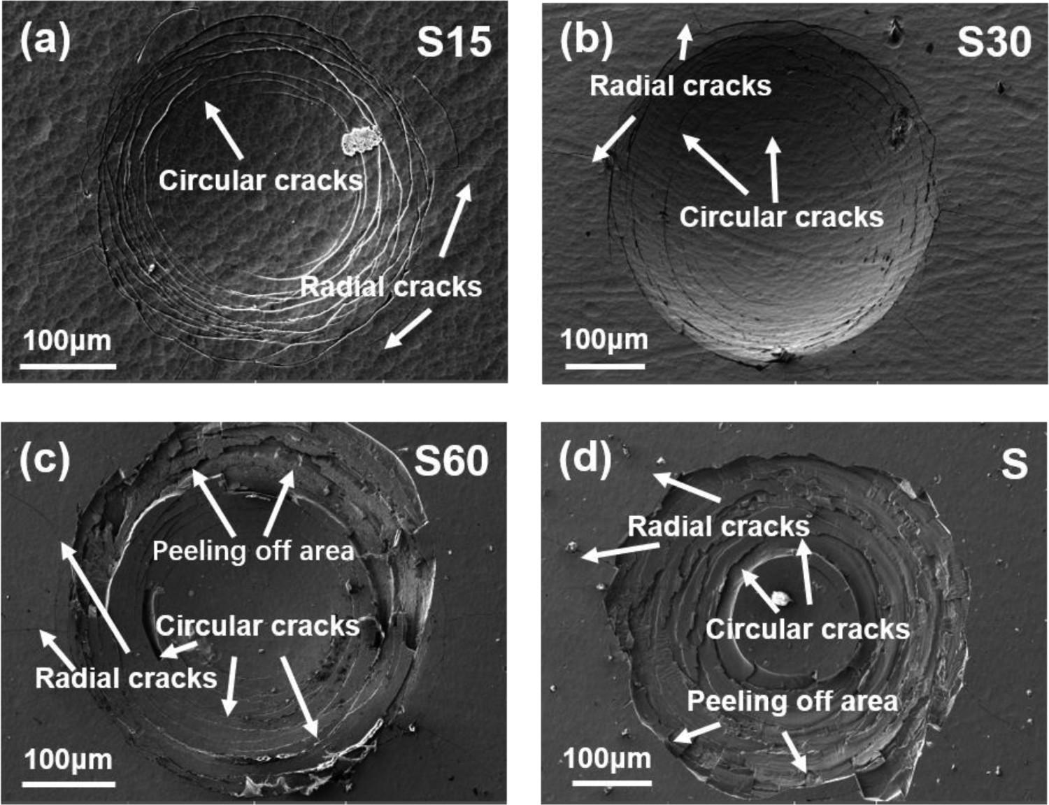
To explore the mechanism of coating cracking, stress fields of the coatings under impact condition were investigated by using finite element modelling. When the incident particle reaches the maximum penetration at 75 ns, the stress in the coatings reached to a maximum value. Displacement and stress fields of coatings at 75 ns were shown in Figure 6. The stress distribution of different structure coatings under impact conditions is almost the same. That is, in the process of impact, high tensile stress was distributed on the undersurface of each TiN interlayer below the impact centre and the surface of coatings near the impact contact radius. In addition, it can be observed that the tensile stress in the bottom TiN layer remained the maximum value in all TiN layers. Since TiN is a typical brittle material, the material will break when the tensile stress reaches the ultimate value of the TiN. Therefore, these two areas are vulnerable areas of the multilayer coatings when subjected to sand impact.
Displacement and max. principal stress (in MPa) fields of four type of coatings at 75 ns: (a) S15, (b) S30, (c) S60, (d) S.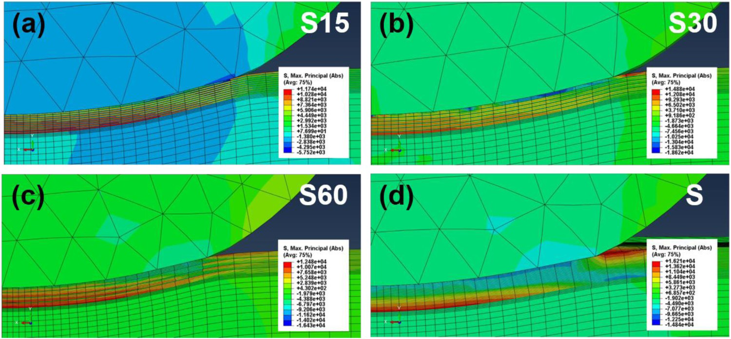
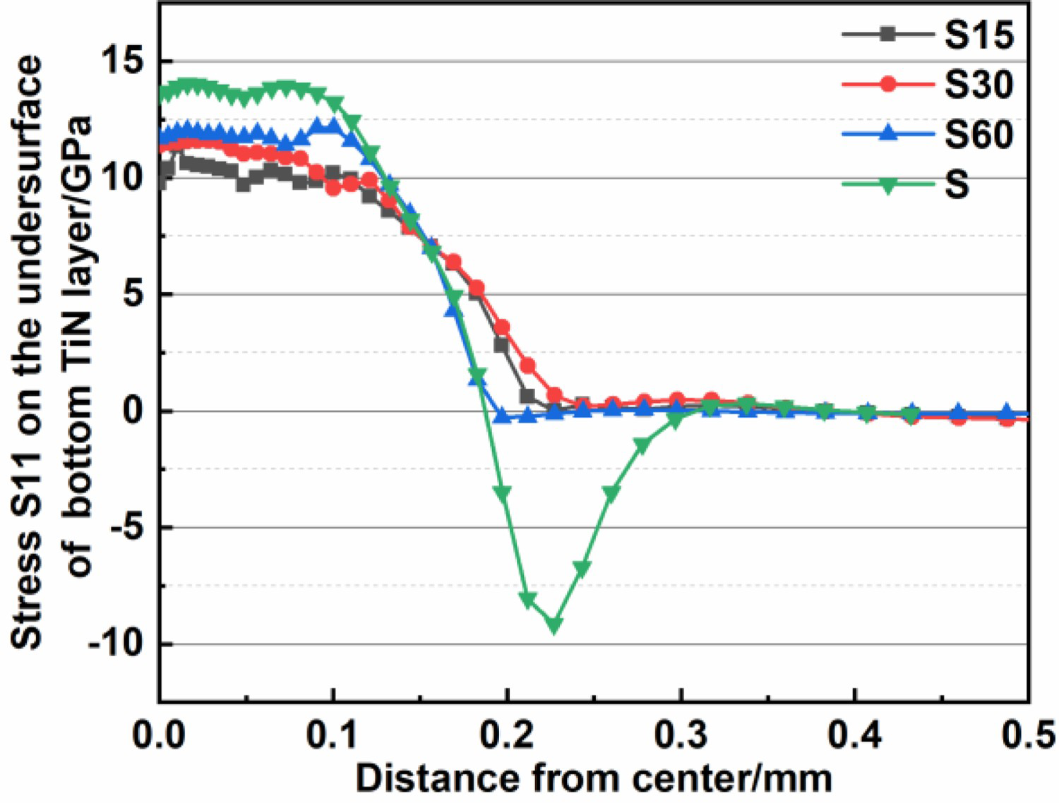
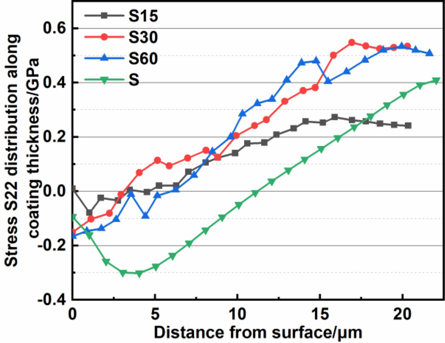
To better explore the stress distribution, all stress components were analysed. It was found that the S11 stress component dominated over all other stress components in the spherical particle impact, which is consistent with the results in the literature [31]. Stress S11 (the stress along X-direction) on the surface of the top TiN layer and undersurface of the bottom TiN layer are shown in Figures 7 and 8. From Figure 7, it is observed that the stress value of coatings below the impact center is very low, which is compressive stress. With the increase of distance, the tensile stress on the surface of coatings increases rapidly, and reaches the maximum at about 0.23 mm from the impact center. Among them, the stress on the surface of the S coating is the largest, reaching about 14 GPa. With the increase of distance, the stress on the surface of each coating decreases rapidly. Similarly, when the particles move to the lowest point, the distribution of stress S11 in the bottom TiN interlayer is shown in Figure 8. It can be seen that the stress values of the undersurface in the coating reach the maximum value just below the impact center. As the distance increase, the tensile stress decreases rapidly. Since TiN is a kind of brittle ceramic material, the ring of high tensile stress distributed at contact radius would lead to the initiation of circular cracks [31,32]. Meanwhile, the tensile stress on the undersurface is the main reason for the interface crack initiation [10]. The propagation and coalescence of cracks would lead to brittle fracture. Among all the coatings, the stress on the surface of S coating is the largest, followed by S60, S30, and S15. The tensile stress decreases with the increase of interface number. Crack propagation and coalescence are easier to occur on the coatings with higher tensile stress. Therefore, S and S60 coatings peel off along the circular cracks. The tensile stress in S15 coating is slightly lower than that in S30 coating, but the number of TiN interlayers in S15 coating is twice that in S30 coating. S15 coating has finer TiN interlayers, but has more vulnerable areas than S30. This means that S15 coating faces more fracture risk than S30 coating. Thus, under the same impact condition, S15 coating has worse tolerance with higher ring crack density compared to S30. In the particle rebound stage, tensile stress along Y-direction would occur in the interfaces due to the deformation recovery mismatch of the ceramic interlayer and the metal interlayer. Stress S22 (the stress along Y-direction) at 135 ns along the coating thickness is shown in Figure 9. It can be seen that S22 stress increases with the increase of coating depth and reaches a maximum at the interface between the coating and the substrate. The S22 maximum stress value of S30 and S60 is the largest and almost equal, followed by S and the smallest is S15. But S22 stress is much smaller than S11 stress. Besides, the bonding strength between TiN and Ti interlayers is excellent due to the application of ion sputtering, which can significantly improve the tolerance of S22 stress. Thus, S11 stress plays a dominant role in interfacial cracks initiation during the impact test.
Distribution of stress S11 on surface of the coatings at 75 ns. Distribution of stress S11 on the undersurface of the bottom TiN layer in coatings at 75 ns. Distribution of stress S22 along the coating thickness at 135 ns.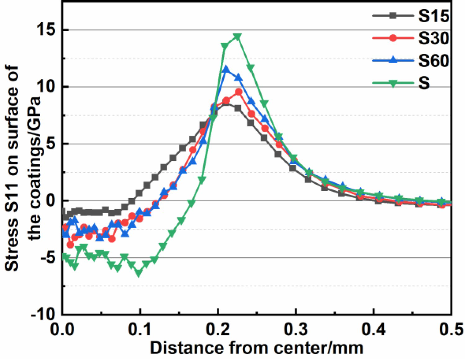
To better understand the crack propagation at the interfaces, FIB experiments were conducted to obtain the cross sections of the coatings in the case that the cracks were perfectly protected. Figure 10 shows the cracks propagation in coatings impacted at an impact angle of 90° and impact velocity of 130 m s−1. Clearly, the vertical cracks propagate downward from the surface TiN layer in all coatings sections. The vertical cracks formation is attributed to the stress concentration at the grain boundaries during deformation by the particle impact. As the stress reached the grain boundary strength, the initiation of cracks would likely occur [33]. As shown in Figure 10(a–c), maximum cracks propagation length in S30 coating is about 4.60 μm. Meanwhile, the cracks propagation lengths in S60 and S15 are 5.12 and 6.14 μm, respectively, which means S30 coating has the best crack propagation resistance among all coatings. Severe brittle fracturing was observed on the S coating due to insufficient toughness and high tensile stress, as shown in Figure 10(d). The cracks in S coating propagate at an angle of 45° from the substrate, showing a typical brittle material crack propagation pattern.
High tensile stress in surface of the S60 coating is the main reason for its higher density and length of cracks compared to S30 coating. Although the tensile stress of S15 coating is slightly lower than that of S30, the S15 coating has more TiN interlayers with high tensile stress, which leads to more vulnerable areas in it. Moreover, the thinner TiN interlayer in S15 makes its resistance to tensile stress weaker [19,34]. These factors result in lower crack propagation resistance for S15 coating than S30 coating. Crack branches and deflections are observed at the interfaces of the Ti and TiN layers in TiN/Ti multilayer coatings. This could be explained by the crack propagation energy was absorbed by the gradient bias Ti layer, leading to the propagation energy inadequate for further crack growth. Such crack branching and deflection can weaken the intensive stress at the crack tips, thereby further restraining the growth. Therefore, the TiN/Ti multilayer coating can improve crack resistance effectively. Vertical cracks are primarily accountable for coating failure, creating ladder-type peeling [20]. The propagation and intersection of lateral and vertical cracks are responsible for the peeling off in coating erosion, reported in many studies [20,35].
FIB cross section after single particle impact of coatings at the speed of 130 m s−1 and erode angle of 45°: (a) S15, (b) S30,(c) S60, (d) S.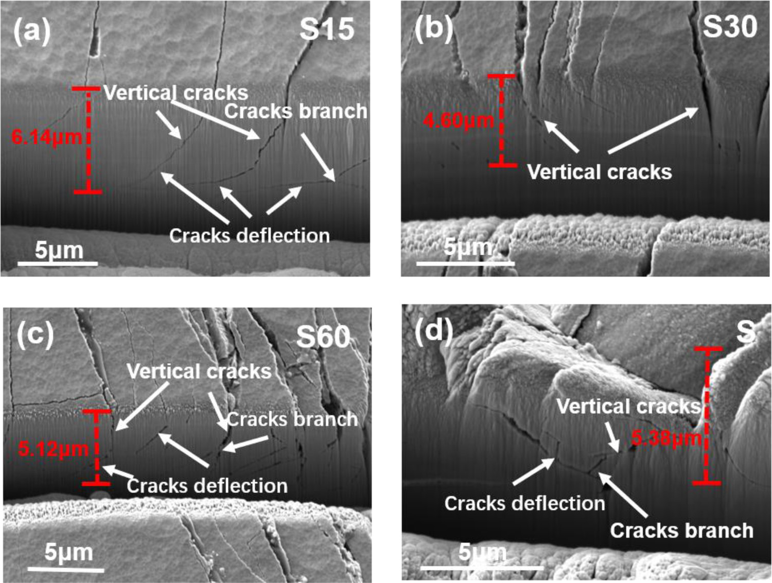
Coatings erosion resistance
To explore the erosion resistance of the coatings, sand erosion tests were performed using a gas blast tester. The mass-loss rate of the coatings calculated is shown in Figure 11. S15 coating displays the highest mass loss rate of 0.0609 ± 0.0036 mg g−1, while those of the S30, S60, and S coatings are 0.0156 ± 0.0028, 0.0234 ± 0.0017, and 0.0313 ± 0.0021 mg g−1, respectively. The lowest mass loss rate shown by the S30 coating indicates that it has the best erosion resistance. The mass-loss rates of the S60, S, and S15 coatings are 1.5, 2.0, and 3.9 times higher than that of the S30 coating. These results indicate that appropriate gradient bias Ti layers can significantly improve the erosion resistance relative to the TiN (S) monolayer coating. Evidently, the mass-loss rate of the coatings is closely related to the crack propagation in the coatings. The longer the vertical crack propagation length inside the coatings, the greater the mass-loss rate of the coatings, which is consistent with the results in previous studies [20].
Mass loss rate of the coatings.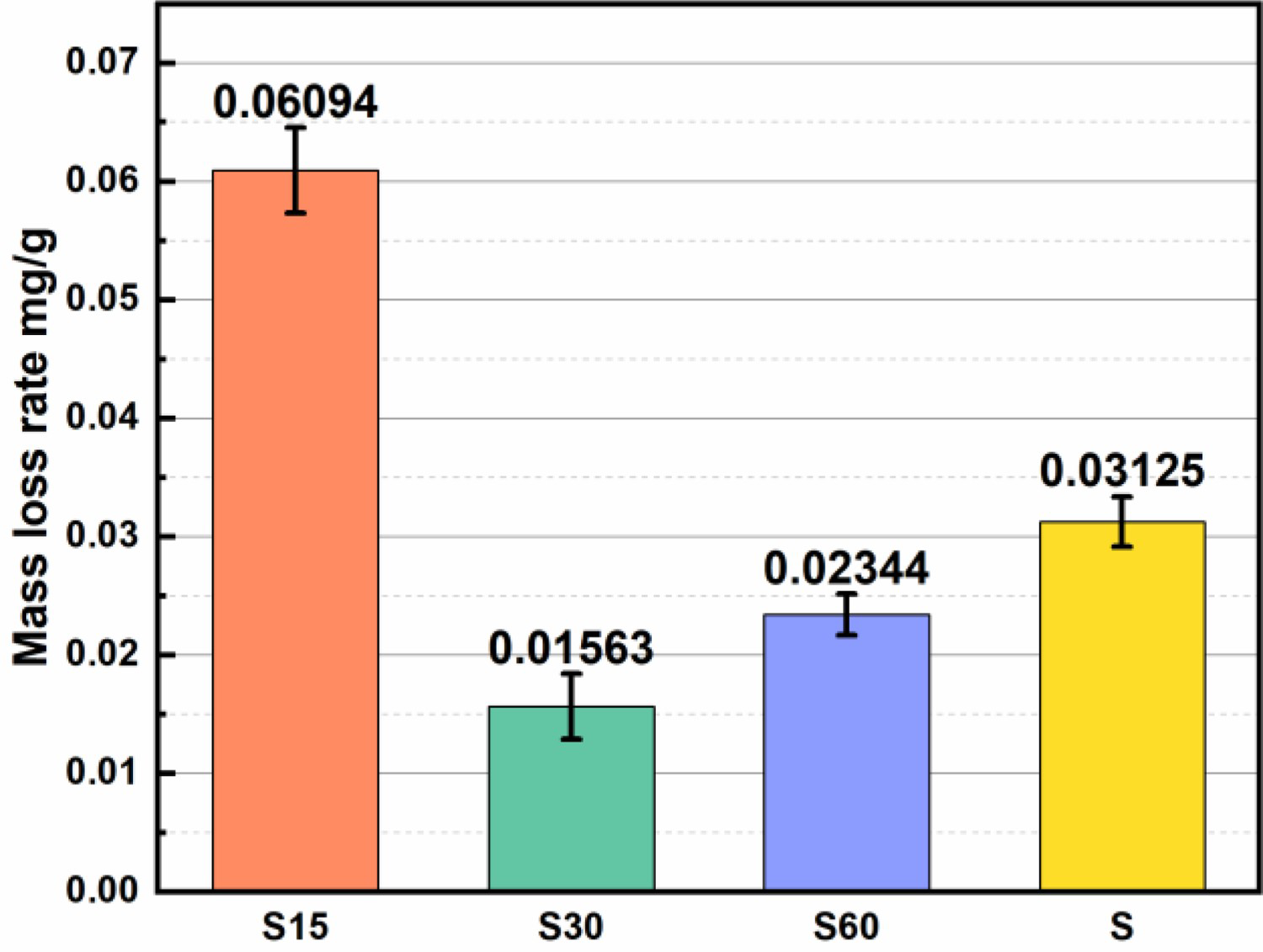
Erosion macrographs of the coatings under the erosion test of 16 g sand supply are shown in Figure 12. Evidently, the S15 coating exhibits the most severe erosion damage, with the substrate exposed in the centre of the eroded areas and many erosion pits at the edges. Conversely, many erosion pits are on the surface of the S60 coating, but few reveal the substrate. The surface damage of the S30 coating is the slightest, characterized by the least erosion pits, and showing a better erosion resistance for this coating relative to the others under identical erosion conditions. Erosion pits on the S coating are much larger than those on the S30 coating, with the substrate revealed in some of the erosion pits. Ploughing and chipping are the main damage forms for the coatings during the erosion, which has been reported in many literatures [10,19,36]. The chipping sites were formed from coating material removal by cracks propagation and coalescence. It can be inferred that erosion resistance of coatings is determined by the inhibition ability on crack propagation. Coatings with higher crack propagation resistance would have more excellent erosion resistance. The erosion morphology of the coating is supported by the results of crack propagation and mass-loss rate of the coatings.
Optical macrographs of eroded area: (a) S15, (b) S30, (c) S60, (d) S.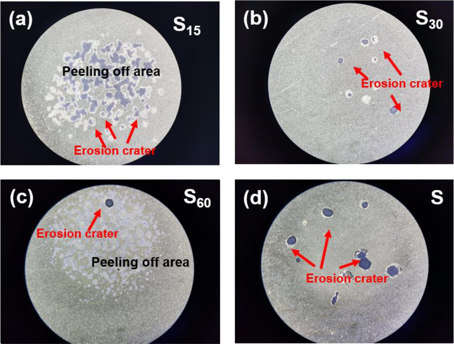
In summary, Ti layer plays an important role in reducing the tensile stress and restrain cracks propagation in multilayers coatings. High tensile stress (S11) accounts for the initiation and propagation of cracks. Crack propagation and coalescence are the main reason for the material removal.
Conclusions
In this study, 15, 30, and 60 min Ti sputtering interval TiN/Ti multilayer coatings and TiN monolayer coatings were prepared using Ti–6Al–4V as the substrate. Based on the examination of the mechanical properties, single-particle impact, FE modelling, and erosion resistance of the coatings, the following conclusions were made:
The high tensile stress distributed at the contact radius on the coating surface is the cause of the circular cracks. And the tensile stress decrease with the increase of interface in multilayer coating. The propagation and intersection of cracks contributed to the material loss of the coatings, and the vertical cracks propagation length dominate the mass loss. Gradient bias Ti layer could reduce tensile stress and restrain cracks propagation, causing cracks branching and deflection. The anti-erosion performance first increased and then decreased with decreasing TiN deposition duration. Coatings with higher tensile stress show worse erosion resistance. But too many thin TiN interlayers with high tensile stress will increase the fragile area, which would reduce the erosion resistance of the coating.