
Abstract
Ultrafine-grained (UFG) Cu deposits were prepared using pulse electrodeposition assisted by hard particle friction under strong cathodic polarisation in an additive-free bath. The effects of hard particle friction on the resulting electrochemical behaviour, microstructure, and mechanical properties of the deposits were studied. The results demonstrate that friction can effectively weaken the concentration polarisation and maintain the stability of the cathodic polarisation process. Periodic growth inhibition and the promotion of lateral growth owing to the applied friction lead to the formation of finer equiaxed grains (130 ± 5 nm). The UFG Cu deposits produced using friction-assisted pulse electrodeposition had a preferential (111) orientation, compared to a (220) orientation in deposits produced using conventional pulse electrodeposition. The corresponding tensile strength was 630 ± 15 MPa and the elongation to failure was 14.5 ± 2.5%. The hardness and surface roughness were 183–204 HV and Ra 46 ± 5 nm, respectively.
Keywords
Introduction
Electrodeposited Cu can exhibit a variety of microstructures, including coarse, micrometre, ultrafine, nano, and twinned grains [1-3]. Of these, ultrafine-grained (UFG) Cu and nanocrystalline (NC) Cu have attracted particular interest over the past two decades owing to their unique mechanical properties [4] such as high strength [5,6], high sensitivity to the strain rate, and reduced strain hardening [7]. This high strength is primarily owing to grain-boundary strengthening, otherwise known as the Hall–Petch relationship [8,9]. Generally, refinement strengthening in electrodeposited metallic films is affected by processing conditions such as the current density, current waveforms, electrolyte composition, and substrate type [10]. In addition, different types of additive that act as inhibitors of grain growth affect grain refinement during the nucleation process [10], leading to unavoidable problems such as sulphur and carbon contamination of the deposits, with minor variations in the additive concentration leading to significant changes in the mechanical properties of the deposit [11,12].
An effective method for obtaining strong cathodic polarisation and thus achieving grain refinement is to control the ratio of the working current density to the bulk concentration of the metallic ions (J/c) [2]. Many studies [10,13] have shown that the grain size can be reduced using a higher nucleation rate and the grain density can be saturated by increasing the current density, with nanoscale grains possible with a sufficiently high current density [14]. However, at high current densities, constrained mass transfer can result in a powdery surface. Interestingly, although Cu dendrites appear at the limiting diffusion current density, the grain size continues to decrease as the polarisation becomes stronger [15]. However, the ensuing stronger concentration polarisation promotes the evolution of hydrogen, complicating the nucleation of Cu. In addition, utilising a high working current density in a low-concentration solution for the purposes of grain refinement is typically avoided given that the quality of deposits is strongly dependent on the polarisation [16].
To avoid the potential deterioration of deposit quality in the process of grain refinement, pulsing is an effective method, and previous studies [1,14,17] have shown that pulse electrodeposition can be used to obtain a more uniform and dense coating while refining the grain size. Shen et al. [18] maximised the control of the concentration polarisation by flushing the cathode surface with a strong electrolyte, leading to a better combination of tensile strength and ductility for NC Cu in an ultra-low sulphate concentration bath. However, this method offers limited control over the hydrogen content in the deposits. It has been reported that the quality of the deposit can be improved by introducing physical friction to the electrodeposition process. Lv et al. [19] reported grain refinement and a dense deposit in Ni electrodeposited with the use of flexible friction. Zhu et al. [20] developed a hard particle friction electrodeposition technique by adding hard particles when polishing the cathode surface, leading to dehydrogenation and NC Ni with a smooth surface. However, the combination of pulsing and physical friction to improve the quality of the deposits has not yet been attempted. To the best of our knowledge, this is the first report on UFG Cu fabricated using pulse electrodeposition assisted by hard particle friction under strong cathodic polarisation.
In this paper, a combination of pulsing and hard particle friction is used to improve the quality and refine the grain of Cu deposits. Three types of electrodeposition – direct-current, pulsed-current, and friction-assisted pulse electrodeposition – were evaluated for UFG Cu electrodeposition at a relatively high working current density in an additive-free bath with a low sulphate concentration. The electrodeposition process was also analysed in terms of its electrochemistry, microstructure, and mechanical properties.
Materials and methods
Specimen preparation
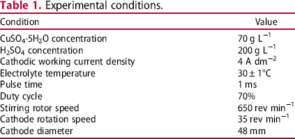
In this work, a rotating SUS304 cylinder was used as the cathode and mechanically polished to produce a mirror effect with #400–5000 SiC paper. The anode was a combination of two phosphor Cu plates in opposition to each other to minimise the polarisation at the anode. Cathodic current density was the average current density when using a pulsed power supply. Table 1 summarises the experimental conditions. In this study, three types of electrodeposition process were tested:
direct-current electrodeposition (DCE) pulsed-current electrodeposition (PCE) friction-assisted pulse electrodeposition (FAPE). Experimental conditions.
For FAPE, it was necessary to carry out DCE for 40 min at half current density (2 A dm−2) without hard particles in advance. After the pre-deposition process, hard particles (ceramic beads) with a diameter of 1 mm and a smooth surface were added to the electrodepositing tank until they covered the surface of the cathode. All subsequent experiments and tests were based on pre-deposition copper substrates. Figure 1(a) shows a schematic diagram of the FAPE process.
Schematic diagram: (a) FAPE and (b) electrochemical testing.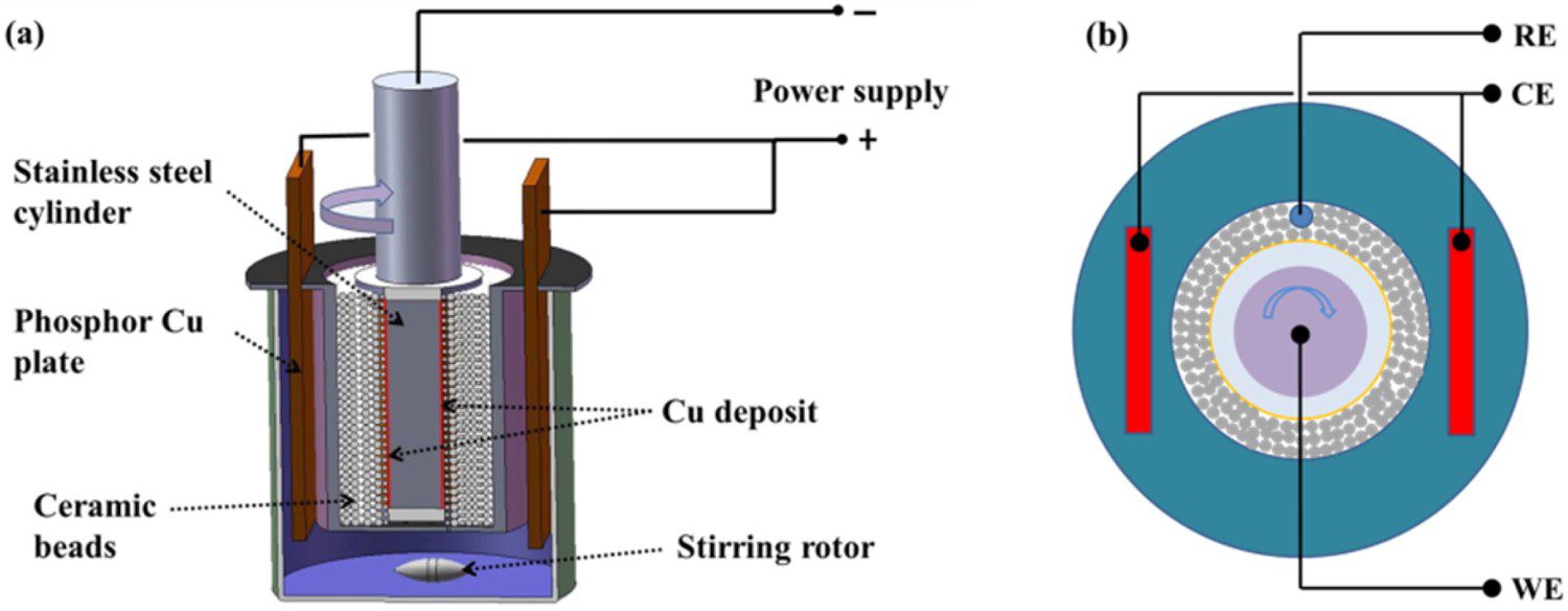
Electrochemical measurements
The electrochemical behaviour of the electrodeposited Cu was measured using a three-electrode system (Figure 1(b)). The cathode and anode were the same as those used in the actual specimen preparation process. A silver chloride reference electrode with a saturated KCl double junction (KCl/AgCl, Ag) electrode was utilised. Polarisation curves were generated in the current density range 0–8 A dm−2 and the potential was swept at a scan rate of 2 mV s−1 from 0 to –800 mV. Under a constant current of 4 A dm−2, the variation in the potential with time over a 20-min period was tested with a sampling interval of 500 ms.
Microstructural characterisation
Various characterisation techniques were implemented to analyse changes in the microstructure for the three processing conditions. A scanning electron microscope (SEM, JSM7200F) was used to observe the specimen and fracture surface. The grain size and distribution of the specimens were investigated using transmission electron microscopy (TEM, JEM-2000EX). The texture of the specimens was measured using a Bruker D8 Advance X-ray diffraction system to examine the crystallographic orientation of the deposits. Electron backscatter diffraction (EBSD, Oxford Nordly Max3) was employed to assess the misorientation distribution of the deposit cross-sections.
Mechanical testing
The mechanical performance of the deposits was evaluated using a tensile tester (INSTRON 5566) and a Vickers microhardness tester (Shimadzu HMV-2000) for FAPE-processed Cu. Approximately 150 μm-thick tensile coupons were prepared with a gauge length of 40 mm and removed from the substrate using electrical discharge machining (EDM). All specimens were tested at a strain rate of 6.7 × 10⁻⁴ s−1. Vickers hardness was measured at room temperature on the polished cross-section of the specimens with a 250 mN indenting load and a 10-s dwell time.
Results and discussion
Electrochemical behaviour
Figure 2(a) presents the polarisation curves for friction-assisted and frictionless electrodeposition. The initial stage of the polarisation curves revealed that both electrodeposition processes were affected by mass transfer. Frictionless electrodeposition occurs under mixed ohmic-diffusion control owing to an inclined limiting diffusion current density plateau, while friction-assisted electrodeposition is under ohmic control owing to the absence of the plateau [21]. The polarisation curves also indicated that friction-assisted electrodeposition had a higher limiting diffusion current density. It is clear that the disturbance of the diffusion layer and the good liquid-phase mass transfer on the cathode surface helped significantly [22].
Influence of friction on cathodic polarization: (a) polarization curves and (b) E/t curves.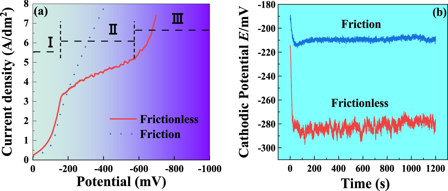
In stage (I) of Cu electrodeposition under ohmic control, the greater cathodic polarisation with friction can be attributed to the increased local current density caused by the wrapping of the hard particles. During the period of mixed ohmic-diffusion control (stage II), the mass transfer process gradually affects the electrodeposition process, and the concentration polarisation becomes more pronounced. Friction-assisted electrodeposition was not affected by the significant concentration polarisation, benefiting from the presence of sufficient Cu ions in the diffusion layer. However, the replenishment of Cu ions within the diffusion layer owing to the stirring of hard particles is eventually disrupted by the difficulty of diffusing Cu ions migrating from the bulk solution to the interior of the mass of hard particles. This means that friction-assisted electrodeposition also has an upper limit for the limiting diffusion current density. In the diffusion-controlled stage (III), the reduction of H+ gradually replaces the deposition of cupric irons. Friction-assisted electrodeposition requires a higher current density to reach the hydrogen discharge overpotential, while the reduction of H+ can occur at any time in the electrodeposition process. Therefore, hydrogen generation does not completely disappear in the presence of hard particles, but the nucleation of hydrogen atoms is interrupted to some extent. In addition, even though hydrogen forms on the cathode surface, the action of the hard particles breaks and separates the hydrogen bubbles, effectively reducing the porosity of the resulting deposit.
Figure 2(b) shows the variation in the potential over a 20-min period during 4 A dm−2 galvanostatic electrodeposition. Friction-assisted electrodeposition had a more positive cathodic potential than unassisted electrodeposition (about 75 mV), and potential fluctuation was much smaller, with the mass transfer at a current density of 4 A dm−2 playing a critical role. The sparse Cu ions in the frictionless electrodeposition diffusion layer preferentially nucleate and grow as protuberances on the cathode surface, where the energy conditions are the most favourable, leading to a rougher microscopic surface morphology. Moreover, irregular growth conditions and asynchronous nucleation processes over the cathode surface result in more complex overpotential fluctuation. During friction-assisted electrodeposition, the presence of a sufficient number of Cu ions in the diffusion layer is a prerequisite for stable nucleation. Hard particle-induced friction achieves a more uniform overall grain growth rate over the cathode surface by inhibiting the tip growth. Furthermore, it can create many defects at these sites, resulting in a relatively consistent nucleation rate during electrodeposition. Friction-assisted electrodeposition, with its relatively consistent nucleation and growth processes, contributes to a more stable cathodic potential.
Microstructural details
Figures 3–4 show four-hour electrodeposited physical images and the 20-min electrodeposited surface morphology, respectively. The results for DCE and PCE were similar, with both eventually deteriorating to a powder-like morphology, while FAPE maintained a consistent Cu deposit with a mirror surface roughness of Ra 46 ± 5 nm. The insufficient Cu ion supporting contributes to the production of a powder morphology, which is completely avoided under FAPE. Even in a powdered state, PCE produces a more homogeneous surface owing to the high density of generated Cu ions and electrons redistributed over the surface at high peak current densities [1]. Moreover, the higher nucleation rate at the peak current density and thinner diffusion layer during the pulse on-time lead the smaller grains to cluster more tightly around the growth defects during the PCE process [23]. The continuous transport of Cu ions to the cathode surface during the pulse off-time also contributes to greater grain agglomeration. The powder morphology has a field-orientated isolated (FI) crystal structure and an unoriented dispersion (UD) structure under FAPE owing to the relatively low J/c ratio and the presence of a predictable inhibitor [2].
Physical images of deposits processed using different methods: (a) DCE, (b) PCE, and (c) FAPE. Surface morphology of deposits processed with different methods: (a) DCE, (b) PCE, and (c) FAPE.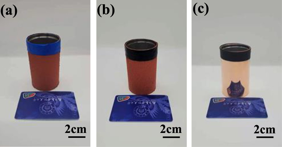
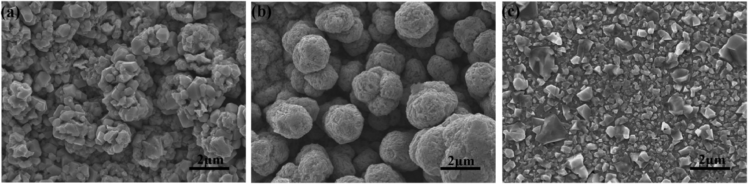
Figure 5 displays the growth mechanism model for FAPE-processed Cu. Hard particles consistently switch contact positions as the cathode rotates and directly block the growth of grains in the normal direction. However, grains can grow for short periods in the concave position where they are not in direct contact with the hard particles, resulting in a more uniform grain growth. The presence of the hard particles also blocks the surface diffusion of adatoms to the growth sites, disrupts the aggregation of adatoms, and increases the population of adatoms on the cathode surface by eliminating impurities and the adhesion of hydrogen bubbles on the cathode surface. This can lead to a reduction in grain size [24]. After a quick release at each contact point, the growing grains at fresh nucleation sites are unstable and prone to lateral growth subject to the next frictional action of the hard particles. Furthermore, during the release times, frequent power shut-offs reduce the ion discharge time and thus limit the growth of nuclei, while the movement of the hard particles during the off-time of the pulse accelerates the replenishment of copper ions in the diffusion layer, facilitating the formation of a homogeneous fine-grain microstructure at higher peak current densities.
Growth mechanism model for FAPE-processed Cu: (a) before hard particle friction, (b) friction process with grain growth in one inhibition–release cycle, and (c) friction process with grain growth in the next inhibition–release cycle.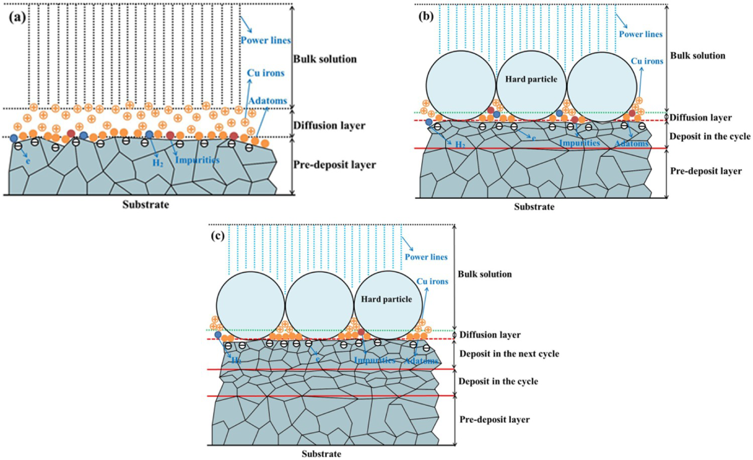
Figure 6 displays TEM bright-field micrographs and the grain size distribution of the Cu deposits. Nano-twins were found under PCE (Figure 6(b), marked with a circle). Xu [25] argued that the stress released during the pulse off-time favours the creation of low-energy twin boundaries. However, the formation of twins is disrupted with the addition of hard particles, presumably because they introduce new compressive stress to the grains and prevent stress relief during the off-time. The finer grain size of FAPE-processed Cu is not only owing to the constant pulsing effect but also to the fact that the hard particles change the grain growth state and the growth environment. Moreover, smaller nuclei result in random discharging behaviour, creating a higher surface quality with the help of controlled concentration polarisation via hard particle friction.
TEM bright-field micrographs and corresponding grain size distribution plot for Cu deposits processed with different methods: (a, d) DCE, (b, e) PCE, and (c, f) FAPE.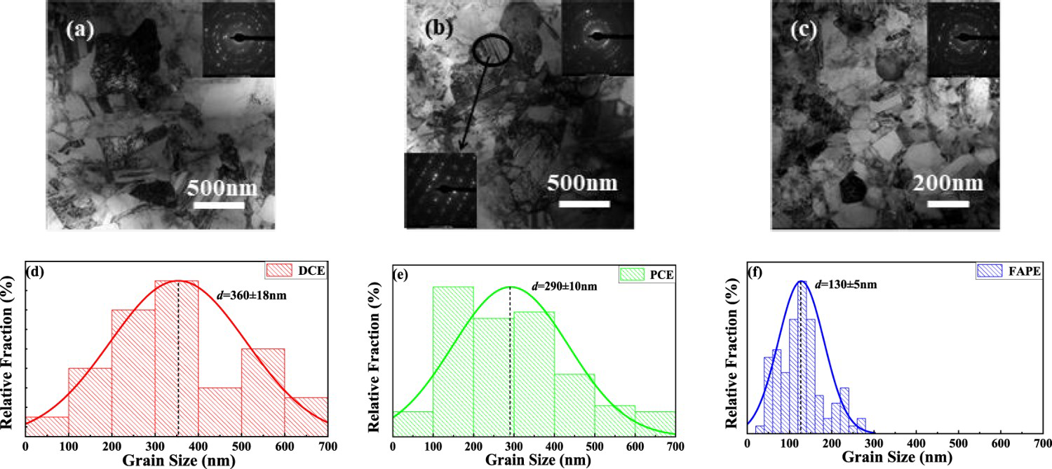
Figure 7 presents the XRD patterns of deposits electrodeposited after 20 min and the respective texture coefficient TC [19]. It shows that DCE-processed Cu had a preferential (111) orientation that is consistent with the tendency of the (111) texture to appear at high current densities [26]. Under PC electrodeposition, the preferential (220) orientation is attributed to the competition between the strain energy and surface energy of the Cu crystallites [27]. In addition, Cu2O diffraction peaks have been found in the XRD patterns of PCE-processed Cu where the higher overpotential caused the current efficiency to decrease, thus leading to the inefficient electrochemical reduction of Cu (II).
XRD patterns of electrodeposited Cu deposits and the respective texture coefficient.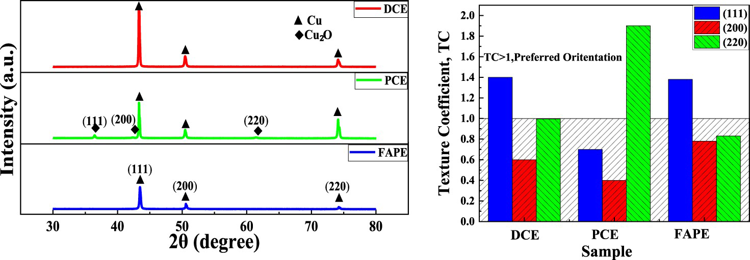
It is well-known that the preferred orientation during electrodeposition is related to the difference in the crystal growth rate and the surface energy [16]. The friction of hard particles on the cathode surface may change the surface energy of certain crystal faces by altering the atomic diffusion and crystallisation process or change the growth rate by removing adsorption species. The preferential (111) orientation of FAPE-processed Cu indicates that hard particles play a significant role in varying the crystallographic orientation. The inhibition of protrusion promotes growth in the valleys on the cathode surface with the use of friction, favouring the (111) orientation. In addition, the hard particles eliminate the co-deposition of hydrogen, further contributing to the (111) orientation. Notably, the intensity of each diffraction peak was reduced, especially that of peaks (111) and (200), which suggests the stronger modification of the (111) and (200) crystal faces. The weakening of the (111) peak may be the result of increasing the stacking fault energy of the deposit [28] owing to the disruption of the twin structure of the low stacking fault energy. The wrapping of hard particles inevitably introduces extrusion and shear behaviour. The shear deformation that often occurs in the (110) direction in FCC materials [29] and the variation of internal stresses owing to the extrusion may explain the weakening of the (220) orientation [30].
Microhardness
Figure 8 shows the cross-sectional microhardness along the growth direction of FAPE-processed Cu deposits. The microhardness decreased in the direction of grain growth, reaching 204 HV on the side near the substrate and 183 HV on the opposite side. The hardness of the deposits was mainly associated with the grain size, similar to a previous study on electrodeposited Cu with gelatin [10]. However, a dominant (111) texture [26] with lower porosity and fewer impurities [19] also leads to higher hardness. Overall, the reduction in hardness could be ascribed to an increase in the grain size, even though this was controlled. The growth of the grains is mainly affected by the inadequate inhibition of hard particles and the extrusion environment [28] under FAPE. However, given the relatively low variation in the hardness, the introduction of hard particles may refine the grain to a certain extent and maintain the uniformity of the grain size.
Microhardness distribution along the growth direction for an FAPE-processed Cu deposit cross-section: (a) microhardness measurement points and (b) microhardness in accordance with the thickness.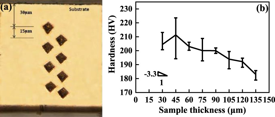
Tensile properties
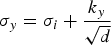
The strength of UFG Cu is generally determined by the grain size, texture, dislocation density [9], and the presence of nano-twins and a bimodal grain size distribution [31]. Figure 9(a) presents FAPE-processed Cu with a strength of 630 ± 15 MPa and an elongation to failure of 14.5 ± 2.5%. The yield strength of FAPE-processed Cu reached 550 ± 20 MPa (as determined using the 0.2% offset method), and it had a rather short work hardening period owing to the exhaustion of dislocation accumulation [32]. The yield strength related to grain size can subject to the Hall–Petch relationship:
Tensile properties and fracture surface morphology: (a) Comparison of the tensile properties of UFG Cu for different methods. (
 is the yield strength, d refers to the grain diameter and
 and
and
 are material property constants. A yield strength in excess of 414 MPa could be explained in four ways using
 = 25 MPa [23] and ky
= 0.14 MPa m−1/2 [23] and d = 130 nm shown in Figure 6. First, the grain refinement and stress generation mechanisms are directly related [30]. The significant grain refinement that occurred after the introduction of the hard particles indicates the presence of compressive stress within the deposit, which leads to an increase in the tensile strength [33].Second, the increase in the dislocation and grain-boundary densities caused by extrusion also leads to improved tensile strength [9]. Thirdly, the constant polishing action of the hard particles on the cathode surface is similar to the application of plastic deformation resulting in an increase in the dislocation density that in turn leads to an increase in the yield strength [34]. Finally, the (111) oriented texture provides higher strength owing to the higher modulus of elasticity [35].
= 25 MPa [23] and ky
= 0.14 MPa m−1/2 [23] and d = 130 nm shown in Figure 6. First, the grain refinement and stress generation mechanisms are directly related [30]. The significant grain refinement that occurred after the introduction of the hard particles indicates the presence of compressive stress within the deposit, which leads to an increase in the tensile strength [33].Second, the increase in the dislocation and grain-boundary densities caused by extrusion also leads to improved tensile strength [9]. Thirdly, the constant polishing action of the hard particles on the cathode surface is similar to the application of plastic deformation resulting in an increase in the dislocation density that in turn leads to an increase in the yield strength [34]. Finally, the (111) oriented texture provides higher strength owing to the higher modulus of elasticity [35].
 ) FAPE, average grain size: 130 ± 2 nm, (
 ) PC(s-100), 290 nm [23], (
 ) ECAP, 400–500 nm [29], (
 ) 93%cryroll, <300 nm [31], (
 ) PC-cupracid, 700 ± 200 nm [36], and (
 ) PC(nt-Cu-20), 400–500 nm [38]. (b) Fracture surface morphology of FAPE-processed Cu.
UFG Cu generally has poor elongation overall owing to the difficulty of dislocations accumulating inside grains with limited space [36]. In the present study, FAPE-processed Cu had a relatively fine fracture elongation. Images of the fracture surface showed a certain number of uniformly sized dimples (Figure 9(b)), indicating deposition without brittle fractures. However, the dimples appeared to be shallow and small, while their size could have contributed to the small grain size, indicating that the ductility remains limited. Notably, strain hardening occurs to counter compressive stress via grain size reduction [37], which would have hindered the dislocation motion and led to greater elongation. Furthermore, a previous study [5] has shown that the equal-channel angular pressing (ECAP) of Cu under back pressure leads to good ductility while maintaining high strength and a high percentage of HAGBs, which is similar to the environment of FAPE-processed Cu. Although more uniform and compact deposits can be obtained under FAPE, further research is needed to elucidate the mechanisms underlying the mechanical properties.
Conclusions
A method for the preparation of UFG Cu using FAPE under strong cathodic polarisation was presented. The concentration polarisation was controlled, and the polarisation process was more stable with the addition of friction. The combination of hard particle friction and pulsing effectively reduced the grain size and resulted in dense uniform deposits. FAPE-processed Cu had a preferential (111) orientation equiaxed microstructure owing to the modification of the crystal faces by the hard particles. FAPE-processed Cu had excellent mechanical properties including a tensile strength of 630 ± 15 MPa, an elongation to failure of 14.5 ± 2.5%, a microhardness of 183–204 HV, and a mirror surface roughness of Ra 46 ± 5 nm.
Footnotes
Disclosure statement
No potential conflict of interest was reported by the author(s).