
Abstract
TiAlN/AlCrSiN multilayer coatings were prepared by arc ion plating. The implements of various thickness ratio (0, 0.89, 1.04, 1.14 and 1.49) of TiAlN/AlCrSiN on microstructure, mechanical properties and thermal stability of TiAlN/AlCrSiN multilayer coatings were investigated. The AlCrSiN single coating without TiAlN inserted layer exhibits a mixed-phase structure of c-AlN and c-CrN, while TiAlN/AlCrSiN multilayer coatings show a single-phase cubic structure. As the thickness ratio of TiAlN/AlCrSiN increases, the critical load of multilayer coating gradually increases up to 99 N, the hardness decreases and the thermal stability improved. The TiAlN/AlCrSiN multilayer coating with a high thickness ratio of 1.49 was able to maintain a single (200) preferred c-TiAlN/AlCrN solid solution phase structure after annealing at 800°C in Ar for 2 h. The obtained single-phase cubic structure of AlCrSiN at room temperature and the improved thermal stability properties can be explained by the template effect of TiAlN on the AlCrSiN.
Keywords
Introduction
AlCrSiN coating has high hardness, outstanding wear resistance and oxidation resistance, which is an ideal coating material for improving the cutting performance of tools and meeting modern high-speed dry cutting [1-3]. The reasons for the multiple excellent properties of AlCrSiN are as follows. On the one hand, the hardness and wear resistance of the coating is improved due to the solid solution reaction of Si atoms and the refinement of grains [4-6]. On the other hand, the coating forms a typical nc-MeN/a-Si3N4 structure and the oxidation formation of SiO2 hinders the diffusion of elements, which enhances the high-temperature oxidation resistance of the coating [7-10]. However, during the deposition of AlCrSiN coating, the alloying of Si and AlCrN will reduce the solid solubility limit of c-AlN in AlCrN and promote the formation of h-AlN during high temperature induced by working, consequently reducing the thermal stability of the coating [11,12]. Therefore, how to inhibit the formation of the h-AlN in the AlCrSiN coatings during deposition and application is of great significance to tool processing.
In previous studies, many novel coating concepts, such as gradient architecture [13,14], multi-component structure [15,16] and multilayered structure [17,18], have been put forward and realized to improve coating performance. Among these structures, the multilayer structure can show a template effect [19]. The template effect between layers in the coating promotes the coherent growth and solid solution of the non-stationary phase, thus achieving the purpose of inhibiting phase decomposition. TiAlN coatings with face-centered cubic (fcc) structures have high hardness, excellent thermal properties and unique age-hardening characteristics, providing an excellent choice for insertion layers in multilayer structures. Yan et al. [20] found that TiAlN/AlN multilayer coatings with TiAlN as the template have excellent mechanical properties, and whether the TiAlN template effect was significantly related to the thickness of the AlN layer is not clear. Studies by Pfeiler-Deutschmann et al. [21] on TiAlN/TiAlVN multilayer films show that the TiAlVN layer with an fcc and wurtzite-type mixed-phase structure grows stably under the action of an fcc TiAlN template. The insertion of an fcc TiAlN template layer can result in a significant improvement in the performance of the TiAlVN coatings.
In this study, to improving the thermal stability of AlCrSiN coatings, TiAlN/AlCrSiN multilayer coatings were designed based on the template effect of the TiAlN layer. And the effects of different thickness ratios of TiAlN/AlCrSiN on the mechanical properties and thermal stability of TiAlN/AlCrSiN multilayer coatings were investigated.
Experimental details
Coating preparation
The substrates of cemented carbide sheets and single crystal silicon slices need to be pre-treated before the coating is deposited. First, the carbide substrates were micro-sandblasted. Then, the substrates were ultrasonically cleaned for 15 min each with acetone, alcohol and deionized water, respectively, and finally mounted onto the rotating rack of the arc ion plating equipment (AS510DMTXB). Deposition of TiAlN and AlCrSiN layers is used the targets of Ti50Al50 (at. %, 99.80 purity) and Al60Cr30Si10 (at. %, 99.80 purity), respectively.
Coating preparation is divided into two steps, argon ion etching and coating deposition. The purpose of argon ion etching is to further remove contaminants from the substrate surface. The main parameters for the argon ion etching are vacuum 4.5×10⁻³ Pa, a substrate bias voltage of −800 V, an argon flow (99.999% purity) rate of 120 sccm, a duty cycle of 80%, rotating frame speed 1 rpm and chamber temperature 400°C. Then, TiAlN and AlCrSiN coatings are deposited sequentially on the surface of the substrates for 60 min. The deposition temperature of the coating is set to 450°C. The deposition parameters for TiAlN/AlCrSiN multilayers (ML) are shown in Table 1. For convenience, the TiAlN/AlCrSiN multilayer coatings prepared under different arc flows are named ML_1, ML_2, ML_3 and ML_4, respectively. The structure diagram of the multilayer TiAlN/AlCrSiN coating is shown in Figure 1. To compare, pure AlCrSiN coating was prepared with a target current of 40 A, N2 flow rate of 1200 sccm and substrate bias of −53 V. Other process parameters remain the same as for multilayer coatings.
Structure diagram of the multilayer TiAlN/AlCrSiN coating. Deposition parameters of TiAlN and AlCrSiN coatings.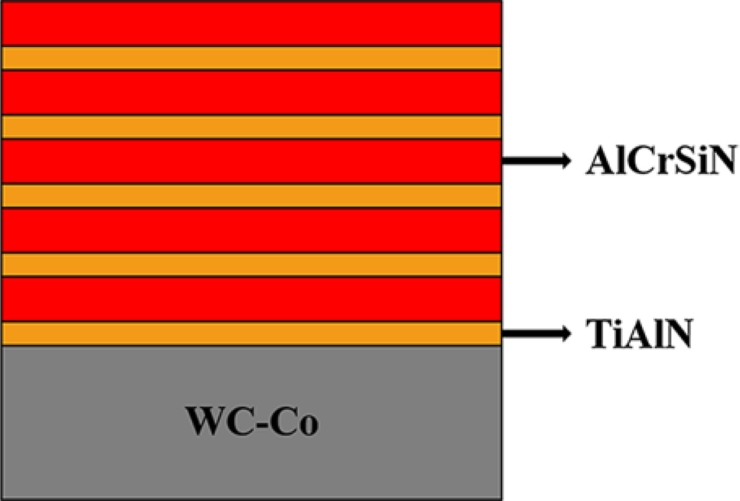

Characterization
The phase structures of the coatings were determined using an X-ray diffractometer (XRD, Bruke D8 Advance, Cu Kα, accelerated voltage 40 kV and current 40 mA). The BCT1000 ball pit tester was used to measure the coating thickness. The WS-2005 scratch tester for measuring the adhesion of coatings was used with the parameters 100 N load, 100 N m−1 loading rate and 5 mm scratch length. MICRO-Vickers hardness tester EM 500-1A was used to test microhardness under a load of 25 g for 30 s and took the average of 5 values. The hardness (H) and elastic modulus (E) of the coating were determined by a nanoindenter instrument (TI-900 Triboindenter, Hysitron, USA) and based on a load–displacement curve. The indentation was carried out under a maximum load of 40 mN, and the loading, holding and unloading times were all 5 s. The effective elastic modulus was calculated as E* = E/(1-v2), and the Poisson's ratio (v) of the coatings was assumed to be 0.25. The cross-section morphology of the samples was examined by field emission scanning electron microscope (SEM, Tescan-Mira3lMU). The thermal stability of the coating was studied by annealing the samples in the OTF-1200X tube furnace from room temperature (RT) to 600, 700, 800, 900 and 1000°C for in argon 2 h, respectively.
Results and discussion
Microstructure
The XRD patterns of AlCrSiN and TiAlN/AlCrSiN coatings are illustrated in Figure 2. It can be observed that the AlCrSiN single coating consists of a mixed-phase structure of c-AlN and c-CrN. The mixed cubic structure of AlCrSiN coating may be caused by alloying with Si, which can reduce the sub-stable solubility limit for AlN in CrN [12]. However, the TiAlN/AlCrSiN coatings are composed of c-AlTiN/c-AlCrN solid solution phase, showing a predominantly preferred orientation of (200) and minor (111) plane, which is typical of the B1-NaCl structure. While after inserting a TiAlN layer into AlCrSiN, the AlCrSiN shows a solid solution cubic phase in the multilayer coating. Therefore, it is shown that the template effect [22-25] plays a role in the growth of AlCrSiN on TiAlN template layers at the interface of nanomultilayer.
XRD patterns of AlCrSiN and TiAlN/ AlCrSiN multilayer coatings.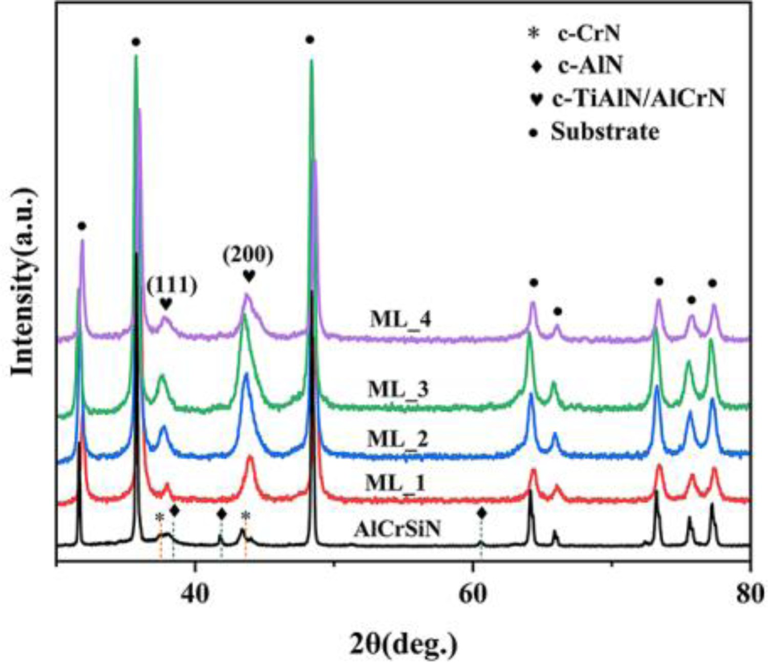
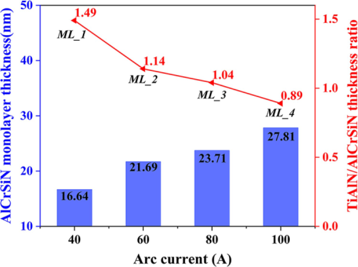
The cross-sectional SEM image of the TiAlN/AlCrSiN multilayer coating (ML_1) is shown in Figure 3. Keen-edged interface between the coating and the substrate is shown in Figure 3(a). According to Figure 3(b) of the local magnification of ML_1, the uniform alternating growth of TiAlN and AlCrSiN shows a continuous dense nanocomposite structure [11,26]. Based on the tests, the thickness of TiAlN is kept constant at 24.71 nm. The thickness of the AlCrSiN monolayer and the thickness ratio of TiAlN and AlCrSiN in the TiAlN/AlCrSiN multilayer coatings prepared under different arc currents are shown in Figure 4. The average thickness of the AlCrSiN monolayer and TiAlN/AlCrSiN multilayer coating are 4.6 ± 0.2 μm.
SEM cross-section of (a) TiAlN/AlCrSiN multilayer coatings and (b) a partial enlargement in (a). AlCrSiN monolayer thickness and thickness ratio of TiAlN/AlCrSiN coatings.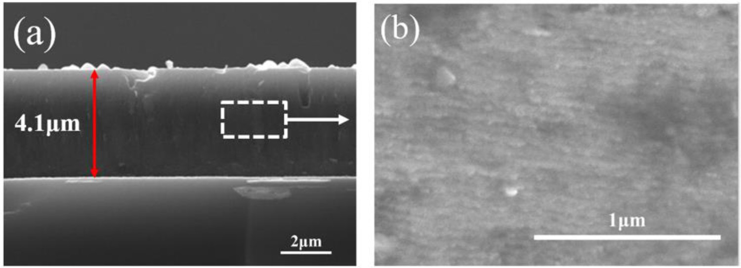
Mechanical properties
The microhardness of ML_1, ML_2, ML_3 and ML_4 are 2970.9, 3028.1, 3251.4 and 3317.4 HV, respectively. Figure 5(a) shows H, E and H/E* ratios of AlCrSiN and TiAlN/AlCrSiN multilayer coatings. The ML_4 coating has the highest H and E of 33.06 and 456.17 Gpa, respectively. It is consistent with the trend of the microhardness data. That is to say, the hardness of the coatings improved as the thickness ratio decreased. As the thickness ratio decreases, the monolayer thickness as well as the content of AlCrSiN in multilayer coating increases, and AlCrSiN has high hardness, so the hardness of TiAlN/AlCrSiN coating increases.
(a) H, E, and H/E* ratios and (b) scratch morphology of AlCrSiN and TiAlN/AlCrSiN coatings.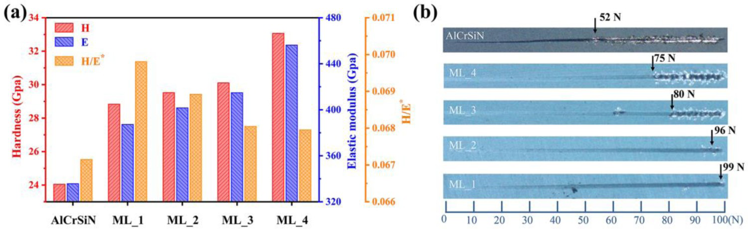
According to research [27,28], the H/E* value was found to be proportional to the crack resistance toughness of the coatings. As shown in Figure 5(a), TiAlN/AlCrSiN multilayer coatings exhibit higher H/E* values than AlCrSiN. ML_1 coating has the highest H/E* value of 0.0698, indicating the best crack resistance of ML_1. The scratch morphology of AlCrSiN and TiAlN/AlCrSiN multilayer coatings is shown in Figure 5(b). The results show that ML_1 requires the highest load for the coating to tear under the same test conditions, and ML_1 has the highest critical load Lc value of 99 N.
Thermal stability
At high temperatures, the coating may undergo defect recovery or recrystallization, accompanying by changes in microstructural and compositional [29,30]. The XRD spectra of the TiAlN/AlCrSiN coatings with various thickness ratio after annealing in Ar at 700–1000°C are shown in Figure 6. After annealing at 600 and 700°C, the coating can maintain the original face-centered cubic structure. At 800°C, the (200) diffraction peak of ML_3 and ML_4 coatings, and Al-rich and Al-poor c-AlMeN (Me = Cr, Ti) phases are formed which may come from the spinodal decomposition of c-AlTiN/AlCrN. However, the ML_1 and ML_2 coatings do not undergo phase decomposition at 800°C.
XRD patterns of TiAlN/AlCrSiN coatings after annealed in Ar at (a) 700°C, (b) 800°C, (c) 900°C and (d) 1000°C.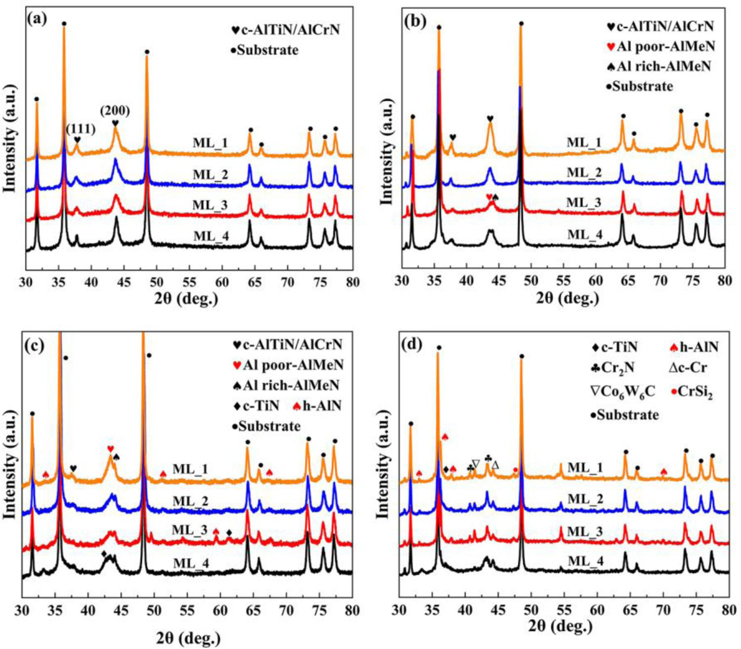
The above results show that ML_1 and ML_2 coatings with a high thickness ratio have better thermal stability. The main reason is that the thickness of AlCrSiN monolayer in ML_1 and ML_2 coatings is smaller than ML_3 and ML_4, and the stacking period of layer to layer is smaller. The template effect of the TiAlN layer is more significant, and the interlayer interface hinders lattice movement and inhibits h-AlN generation [20,26], so there is better thermal stability.
After annealing at 900°C, c-AlTiN/AlCrN decomposed into Al-rich and Al-poor c-AlMeN (Me = Cr, Ti), and h-AlN and c-TiN phases are identified, indicating that spinodal decomposition occurs in all coatings, and part of the Al-rich c-AlTiN/AlCrN phase transforms to h-AlN phase. Upon annealing at 1000°C, the h-AlN can be obviously observed. At the same time, the Cr2N phases, Cr phase and CrSi2 phase are found, indicating that the break of Cr–N bonds in the AlCrN phase at evaluated temperatures and the N-loss [31,32]. Furthermore, a part of Cr reacts with Si3N4 to form CrSi2 [11,33]. Co6W6C is also detected in the coating by XRD, indicating that the Co, W and C in the matrix begin to diffuse into the coating at 1000°C. The phase decomposition process of multilayer coatings takes place over a wide temperature range of 800–1000 °C. These results above suggest that the TiAlN insertion layer slows down the thermal decomposition of the AlCrSiN sublayer, and the thermal stability of multilayer coatings with TiAlN as a template is improved [34,35].
Figure 7 describes the microhardness, H, E and H3/E2 of AlCrSiN and TiAlN/AlCrSiN multilayer coatings after heat treatment at different temperatures in Ar. Monolayer AlCrSiN has a lower hardness than multilayer coatings after annealing at different temperatures. The result suggests that TiAlN inserting layer increases the thermal stability of TiAlN/AlCrSiN multilayer coating. Below 800°C, the hardness of the TiAlN/AlCrSiN coatings shows a slow rising trend, which is caused by the decomposed subphase as shown in Figure 6. The decomposition of sub-phases may result in the decrease of average grain size and the lattice mismatch at the phase interface, forming a coherent strain region, thereby hindering movement of dislocations [36]. From 800 to 900°C, the hardness of ML_3 and ML_4 coatings decreased slightly, which is mainly due to the decomposition of c-AlCrN/AlTiN [37] and the appearance of brittle phase h-AlN in the coating. However, the hardness of ML_1 and ML_2 coatings almost keeps constant. The result is consistent with Figure 6(b) and (c). The template effect is more pronounced with increasing TiAlN/AlCrSiN thickness ratio. Therefore, the thermal stability of ML_1 and ML_2 coatings with a high TiAlN/AlCrSiN thickness ratio is better. Above 900 °C, the hardness of the coatings decreased rapidly, which is mainly due to the cubic phase structure in the coating transforms into the hexagonal phase (Figure 6). In addition, the diffusion of matrix elements into the coatings will also cause a decrease in hardness [38].
(a) The microhardness and (b) the H, E and H3/E2 of AlCrSiN and TiAlN/AlCrSiN multilayer coatings with different annealed temperature.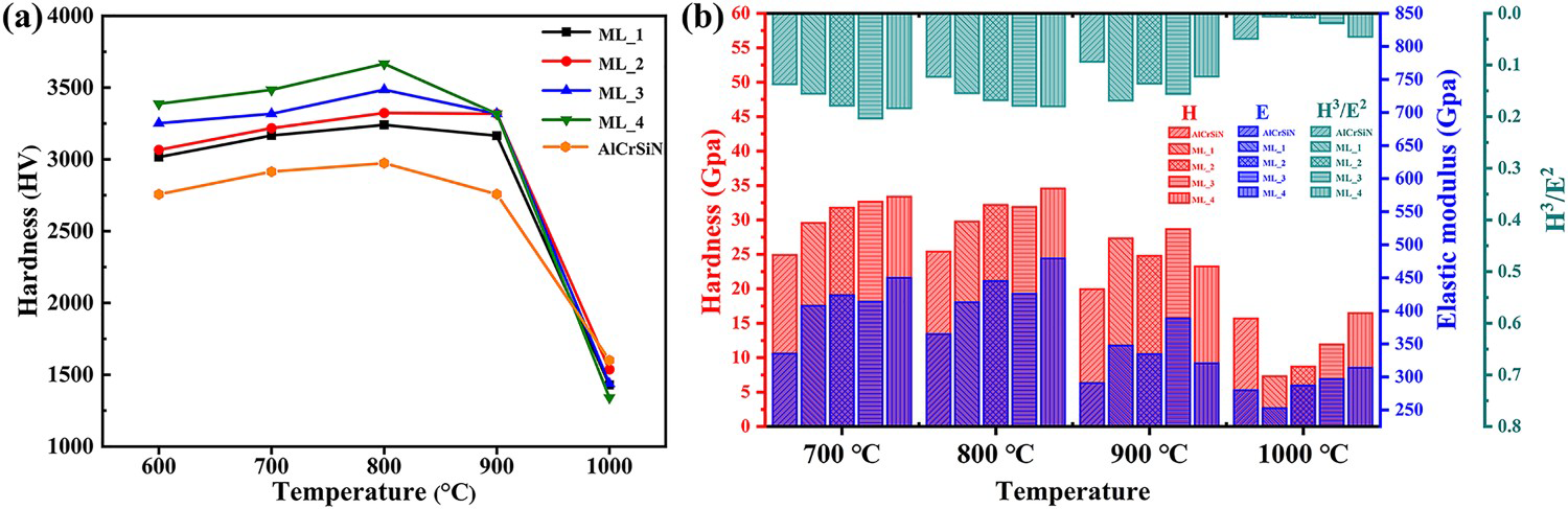
Conclusions
TiAlN/AlCrSiN multilayers with different thickness ratios were prepared by arc ion plating, and its microstructure, mechanical properties and thermal stability were investigated. The results show that the AlCrSiN single coating is a mixed c-AlN and c-CrN structure, while the TiAlN/AlCrSiN multilayer coating shows a single-phase cubic structure. As the thickness ratio of TiAlN/AlCrSiN increases, the adhesion strength of multilayer coating gradually increases up to 99 N, the hardness decreases, and the thermal stability improved. The TiAlN/AlCrSiN multilayer coating with a high thickness ratio of 1.49 was able to maintain a single (200) preferred c-TiAlN/AlCrN solid solution phase structure after annealing at 800°C in Ar for 2 h. The obtained single-phase cubic structure of AlCrSiN at room temperature and the improved thermal stability properties can be explained by the template effect of TiAlN on the AlCrSiN.
Footnotes
Disclosure statement
No potential conflict of interest was reported by the author(s).
Data availability
The data that support the findings of this study are available within the article.