
Abstract
Multiwalled carbon nanotubes (MWCNT) were electrophoretically deposited from an environmentally friendly aqueous solution on aluminium current collectors which were carbon coated by physical vapour deposition. The carbon coating proved to be stable under electrophoretic deposition (EPD) conditions up to EPD voltage of U = 50 V and avoided any undesirable oxidation of the aluminium during the deposition process. The kinetics of the deposition was described and could be easily controlled by the suspension concentration and the deposition time. The deposition rate at U = 50 V is about 0.03 mg cm−2 min−1. As anodic oxide formation could be prevented the electrical contact to the current collector was improved allowing the surface area to be increased by MWCNT to be used as a double-layer capacitor. The gravimetric capacitance obtained was about 8 F g−1.
Keywords
Introduction
Since the groundbreaking work of Iijima [1] on multiwalled needle-like tubes of graphitic carbon in 1991, the publications dealing with carbon nanotubes (CNT) are numberless as at least demonstrated by Atiq et al. in 2020 [2]. Already in 1997, Niu et al. propagated the application of CNT as electrochemical double-layer capacitors (EDLC) due to the small distribution of pore size, highly accessible surface area, high conductivity and stability [3]. The electrophoretic deposition (EPD) was published first as a suitable method to produce CNT layers from organic solvents on metallic substrates such as aluminium by Du et al. in 2002 [4,5]. Aluminium as a thin film, which was vapour deposited on silicon as a substrate for the EPD, was used later by Sakar et al. [6], but unfortunately, the authors did not report about the application of their produced layers. In 2006, Du and Pan used the EPD of CNT to form EDLC on nickel as a current collector. After a heat treatment at 500°C for 30 min in an inert or reducing atmosphere, respectively, they reported a capacitance of 21 F g−1 [7]. Unfortunately, this paper does not inform on the reference, the mass of active material or the mass of the electrode. The heavy metal nickel was also used by Kumar et al. as current collector and substrate for the EPD of CNT [8]. Thomas et al. electrophoretically deposited layers of MWCNT from an aqueous suspension on stainless steel [9]. Okamura et al. used ITO coated glass as a substrate for the EPD from an organic suspension [10]. Summarizing the literature, it seems obvious that the EPD is a facile and cost-efficient method for producing EDLC of MWCNT (see inter alia [11]). The use of a purely aqueous suspension represents an environmentally friendly solvent. The light metal aluminium as a current collector has a positive effect on the gravimetric capacity of the whole electrode in comparison to other metals. Schneider et al. have recently shown that the EPD of MWCNT on aluminium from an aqueous suspension sufficiently works, but the formation of a thin anodic oxide film on the aluminium substrate simultaneously to the EPD cannot be avoided [12]. The lower capacitance of this oxide film limits the total capacitance of the electrode and the potential of the MWCNT as EDLC cannot be exploited. Therefore, the present work focuses on the prevention of such anodic film formation during the EPD. Current collectors coated with carbon are used in lithium-ion batteries to reduce the contact resistance to the active material as well as a corrosion protection layer [13,14]. Du et al. also seem to have encountered the pore problem of the oxide-covered current collector and tried to achieve better performance by pre-coating nickel as a current collector with CNTs [15]. Kanakamedala et al. [16] used an electrospray process to produce a seed layer of CNT on an isolated substrate. Inspired by the literature, a thin and simple carbon coating, but not consisting of CNTs, on the aluminium foil is investigated in the presented work. It is suitable as a current collector of EDLC and formed via EPD from aqueous suspensions. The present work focuses on the suitability of carbon-coated current collectors (CCCC) of aluminium as a stable and robust electrode for EPD and the study of the kinetics of EPD of MWCNT from an aqueous solution on CCCC for EDLC applications.
In case of success, the produced EDLC could, in turn, offer the possibility for further modification, wet-in-wet, e.g. by electrophoretic or electrochemical deposition of transition metal oxides or polymers for hybrid capacitor applications [17-19].
Materials and methods
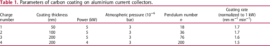
Thin aluminium foils (Al: 99.3 wt-%, thickness 15 µm) were used as current collectors coated with carbon (thickness 50, 100 and 200 nm).
The carbon coating was done by physical vapour deposition (FHR Anlagenbau GmbH) by using the horizontal inline system FHR.Line.600.H. The deposition was done by DC magnetron sputtering from a 99.99% pure carbon target in Ar atmosphere. The aluminium foils were fixed on the carrier. Before coating, a pre-treatment was carried out in vacuum by inverse sputter etching at 1 kW.
The measurement of the thickness of the carbon coating was carried out with a profilometer Tencor Alpha Step 500. The stylus-based surface profiler measured the step heights of surfaces with a resolution of 2 nm at max. 13 µm step height. The measurement was carried out ex situ in a separate coating process in which the carbon was applied to glass substrates that were in the identical position as the aluminium substrates used later. In this way, the coating parameters were validated, and the actual coating process was defined.
Parameters of carbon coating on aluminium current collectors.
The commercially available MWCNT (Baytubes® C 150 HP, outer diameter 13–16 nm, length > 1 µm, bulk density 140–230 kg m−3) [20,21] were functionalized in-house to prepare a stable and suitable aqueous suspension for the EPD process. The procedure used is based on literature [22,23,24] as well as on own preliminary studies [25] and was recently described in detail [12]. Slight modifications of the functionalization and suspension were done in the present work:
The MWCNT concentration in the functionalization routine was quadrupled amounting to 6 g MWCNT, and the separation process was additionally supported by using a centrifuge. The dispersing volume contains MWCNT (0.1, 0.2 or 0.3 g) in 40 mL ultra-pure water. The 40 mL were filled up to 250 mL (MWCNT concentration: 0.4, 0.8 or 1.2 g L−1).
The EPD was carried out in a 2-electrode cell. The carbon coated aluminium foils were used as anode material as received without further pretreatment or cleaning. The anode surface area was defined with a sample holder and amounts to 2.5 cm × 8 cm. The relatively large area allows to carry out various subsequent investigations on samples with identical genesis. A platinized titanium expanded metal was used as a cathode. A potentiostate IMP-88-PC-200 V (IPS Elektroniklabor GmbH & Co. KG, Germany) was used as power source.
To achieve the EPD voltage (U = 50 V), a ramp of 1.67 V s−1 was used. The suspension was slightly agitated. After the deposition, the samples were pulled out of the suspension under voltage control. Finally, the samples were dried and weighed again.
The adhesion of the deposited MWCNT to the CCCC was tested by simply bending the foils by hand. The bending angle was set without bending mandrel using a geo-triangle and the coated foils were then visually evaluated.
The substrate (CCCC) characterization was carried out in a standard flat cell. The 3-electrode arrangement consists of a saturated Hg/HgSO4 reference electrode, platinized expanded metal as a counter electrode and aluminium or carbon coated aluminium foil as a working electrode. The electrolyte was 74.2 g L−1 sodium acetate and 2.9 gL−1 acetic acid in deionized water.
The capacitance determination was carried out in a symmetric 2-electrode screw cell (Swagelok®, diameter 1 cm). The electrochemical setup is described in detailed in a previous work [26]. The electrolyte consisted of 1 M tetraethylammonium tetrafluoroborate in propylene carbonate. The voltage range of the cyclic voltammetry was between −2.5 and +2.5 V (dV/dt = 50 mV s−1). The capacitance was determined according to the following equation:

Results and discussion
The carbon coated aluminium foils were proved to be well adherent and robust in handling (Figure 1). Figure 2 shows only a slight thickness fluctuation depending on the position of substrates on the carrier. Undeposited areas, macropores and cracks can be excluded after visual evaluation.
Simple test of adhesion and robustness of CCCC with a thickness of the carbon coating of 200 nm. Coating thickness measured versus the substrate position on the carrier during the physical vapour deposition process.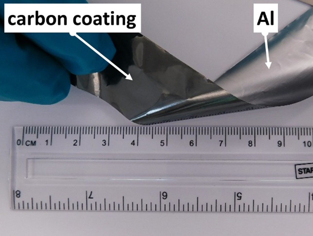
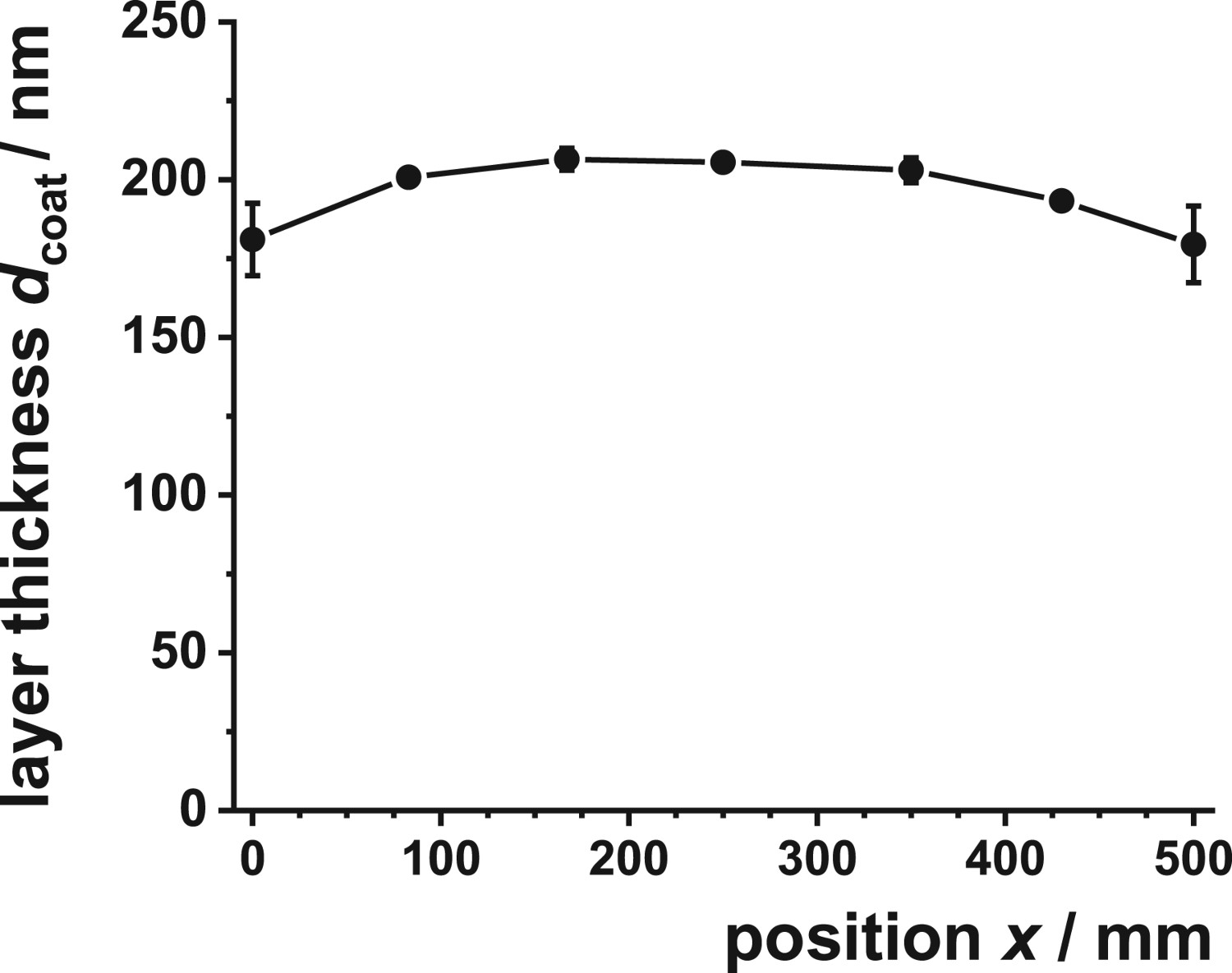
Figure 3 shows the behaviour of the CCCC in comparison with uncoated aluminium foils under potentiodynamic polarization in a highly conductive sodium acetate buffer solution (pH 5.9). The voltammogram on bare aluminium is characterized by a current rise at about 0.4 V vs. SHE and reaches a current plateau indicating the anodic oxide formation according to the high field mechanism [27].
Anodic sweep of linear sweep voltammograms on bare aluminium and CCCC with various coating thickness.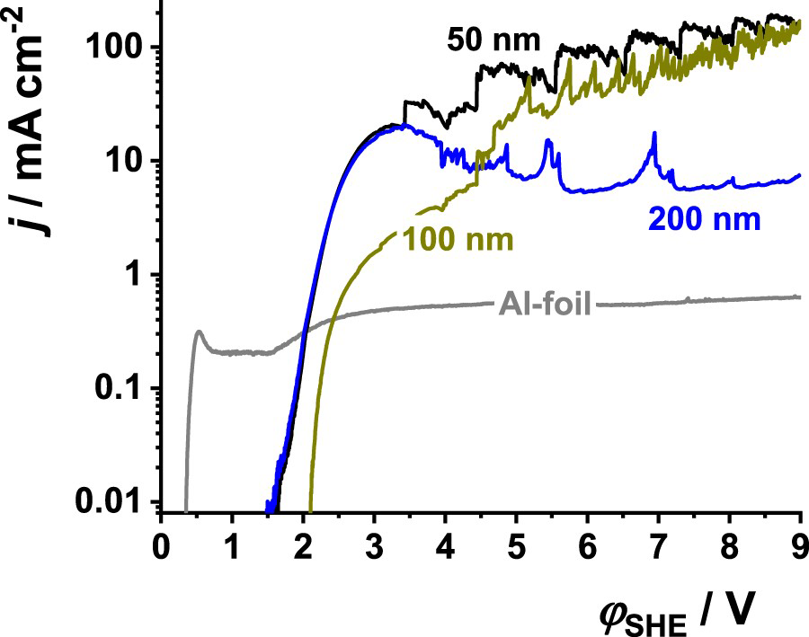
In contrast, the voltammograms on CCCC show a current rise at about 1.5–2 V vs. SHE. The current continuously increases and reaches approximately 200 mA cm−2 at 9 V in maximum. Carbon electrodes are well known as inert electrode material used in technical electrochemistry [28]. Therefore, water splitting and anodic oxygen evolution (Equation (2)), respectively, cause the increasing current.


At high current densities (>20 mA cm−2), the current oscillates due to the formation and desorption of gas bubbles. At the associated high overvoltage, the formation of carbon dioxide (Equation (4)) makes up a minor part of the consumed charge [29].


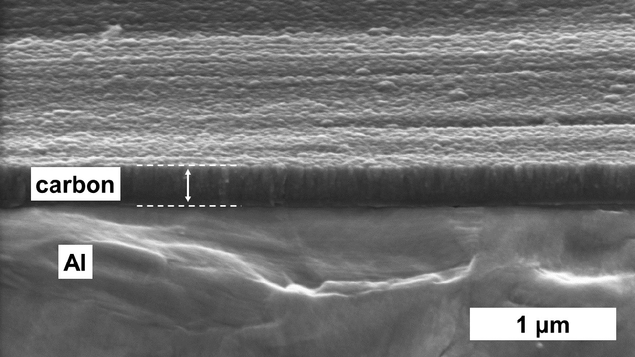
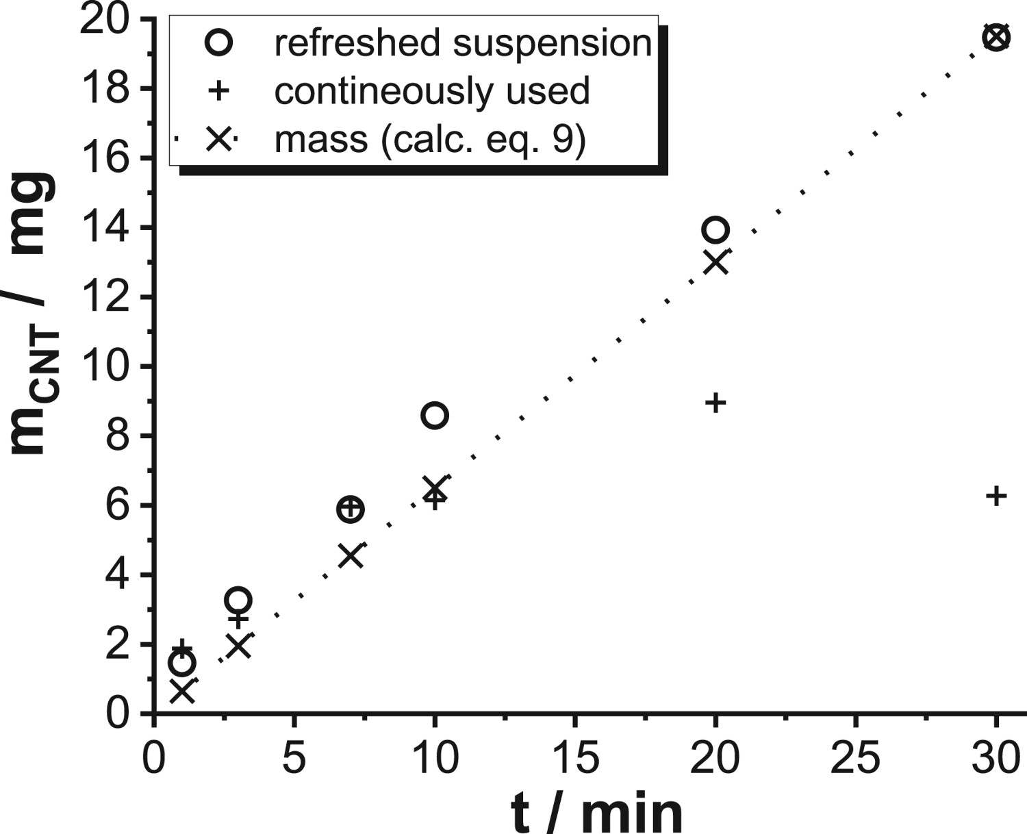
Considering the electrochemical reactions which would consume carbon as well as the desorption of the gas bubbles which results in mechanical stress on the surface similar to the cavitation, the carbon coating might be destroyed over the time. This explains the visibly exposed aluminium surface of the sample coated with only 50 nm thick carbon after the experiment. The samples coated with carbon of 100 and 200 nm thicknesses, respectively, were stable. Figure 4 shows the current characteristic of the CCCC in ultra-pure water at an applied voltage of U = 50 V, typical for EPD. All CCCC are stable as exemplarily shown for the sample with the 200 nm thick coating in Figure 5.
Voltage controlled ramp hold attempts on CCCC in ultra-pure water. Scanning electron microscope cross section of CCCC after the experiment shown in Figure 4.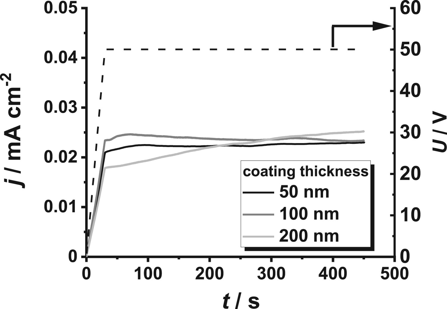
In a subsequent step, the EPD of MWCNT was carried out depending on the applied potential. With increasing applied voltage, which implies an increasing field strength E (Equation (6)), the migration speed υ (Equation (7)), as well as the gravimetrically determined deposited mass increases (Figure 6).
Migration speed and the deposited mass of the MWCNTs depending on the applied potential.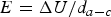

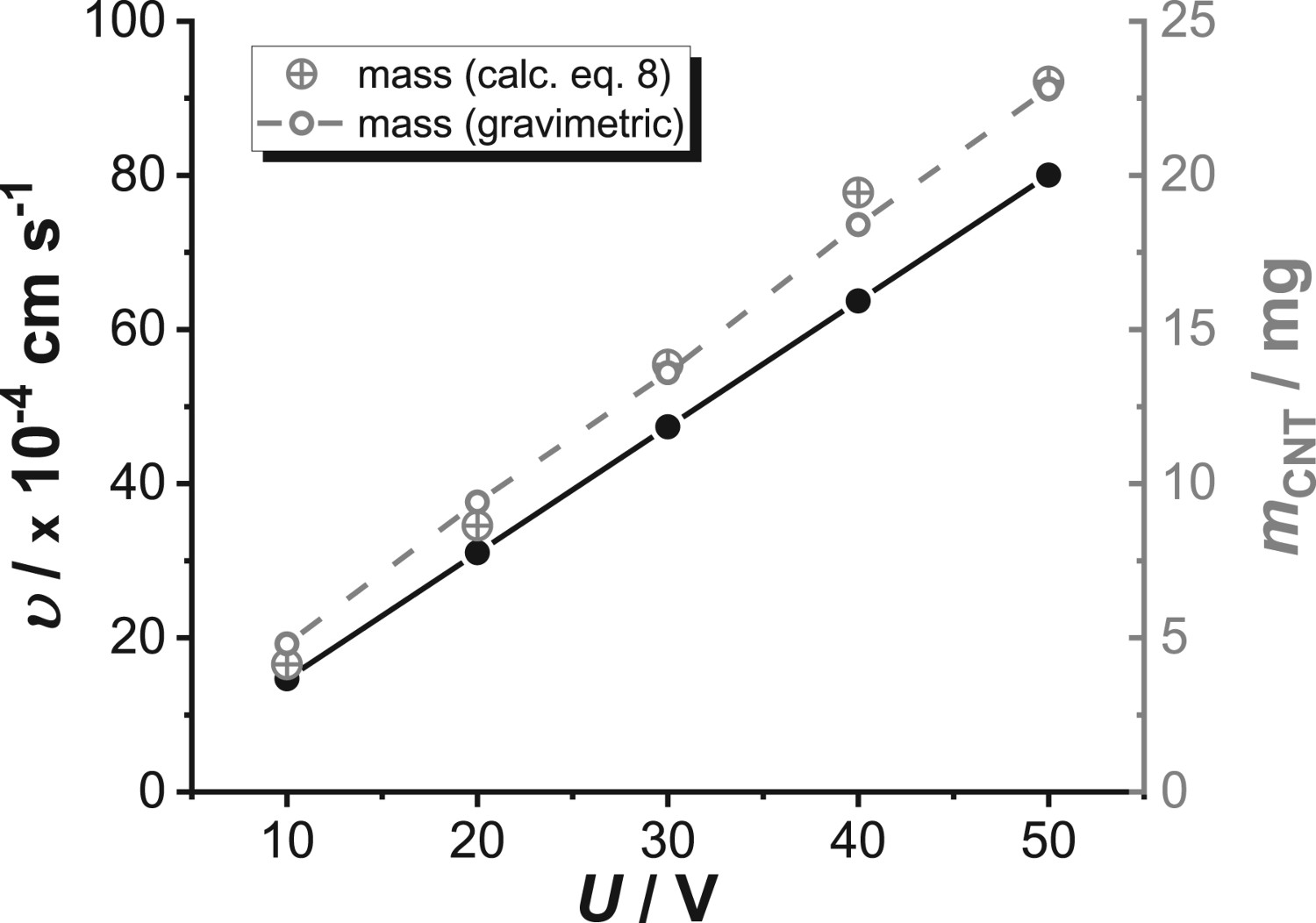
In addition to the gravimetrically determined mass, Figure 6 shows the mass calculated by using Equation (8) as first described by Hamaker [31,32]:
Deposited mass of MWCNTs depending on the time of deposition at U = 50 V from refreshed suspensions as well as continuously used suspensions.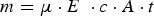
This problem can be solved by the introduction of a correction factor f which modifies Equation (9) as follows [33]:

Figure 8 shows a typical current response to the exciting voltage during the EPD of MWCNT. In agreement with the literature [34] and as in detail described in [12], the authors assume water splitting as a source of the current density. The potential drop on the electrodes due to water splitting can be assumed to be approximately 1 V. Consequently, the potential drop over the suspension is ≈ 49 V. This corresponds with a field strength of E ≈ 16 V cm−1 and is almost constant over the time of deposition.
EPD of MWCNTs on CCCC.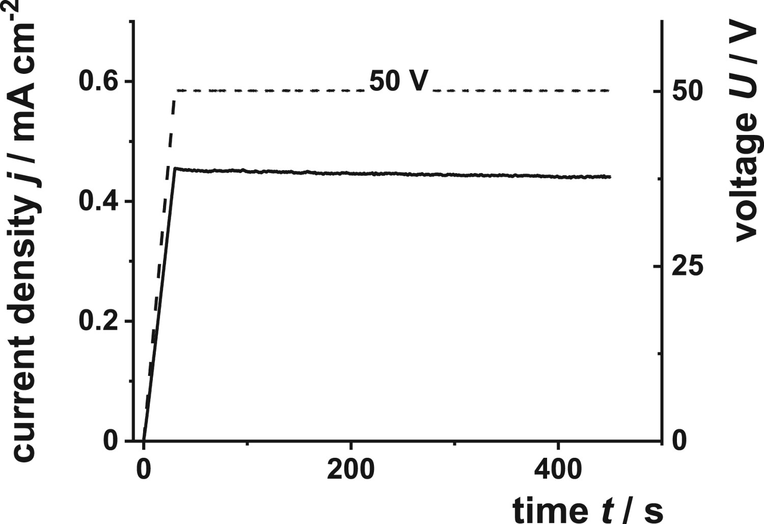
The present results confirm the CCCC as a suitable substrate for depositing CNT from aqueous suspension without simultaneously forming anodic aluminium oxide film between the MWCNT layer and the current collector (Figure 9). A further simple bending test shows that the deposited MWCNT layer is well adherent and sufficiently robust for further handling, e.g. wrapping for cylindrical capacitor designs (Figure 10). In concave bending up to 180°, no cracking or delamination was visible.
Scanning electron microscope cross section of a CCCC after EPD with MWCNTs. Simple bending test to evaluate the adhesion and robustness of CCCC after EPD with MWCNTs.
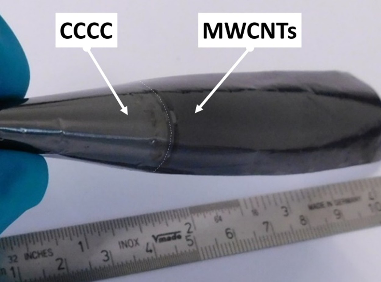
Figure 11 shows the cyclovoltammograms (CVs) on MWCNT on CCCC electrophoretic deposited with identical parameters but dependent on the concentration of MWCNT suspended in pure water. All graphs show a slight tilting, representing the electrical series resistance (ESR) (for details see [26]) of these non-ideal capacitors. The faintly hinted peaks represent a pseudo-capacitance due to the formation of C–O groups on the surface of the MWCNT [35-37]. The higher the concentration of MWCNT in the suspension the higher the current density. The increasing current density correlates with a higher active surface due to the growth of the MWCNT layer thickness with the typically open porous structure.
Cyclovoltammogramms in 1 M tetraethylammonium tetrafluoroborate in propylene carbonate to determine the double-layer capacitance of the electrophoretic deposited MWCNT layer depending on the material usage.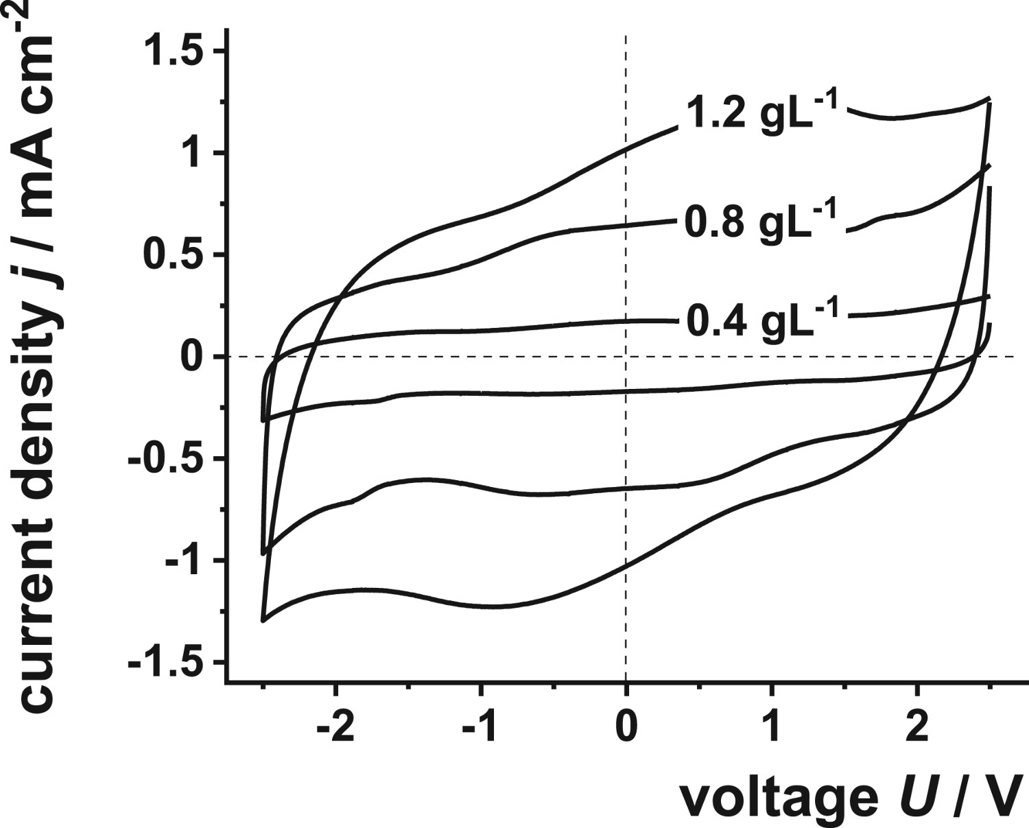
Consequently, the calculated capacitance (Equation (1)) normalized to the geometric electrode area increases with the increasing concentration of the EPD suspension (Figure 11). Again, if the current density, as well as the calculated capacitance, are normalized to the gravimetrically determined mass of the MWCNT the CVs are almost identical and the capacitance is approximately constant (Figure 12). This means, an increasing layer thickness does not necessarily block underlying active surface areas. However, this is only valid in the range of the investigated layer thickness and might change at a higher thickness as the slight tendency of the gravimetric capacitance implies (Figure 13). This should be an issue for further investigations.
CVs shown in Figure 11 normalized to the material usage. Capacitance normalized to the geometric area as well as on the gravimetric determined mass depending on the material usage.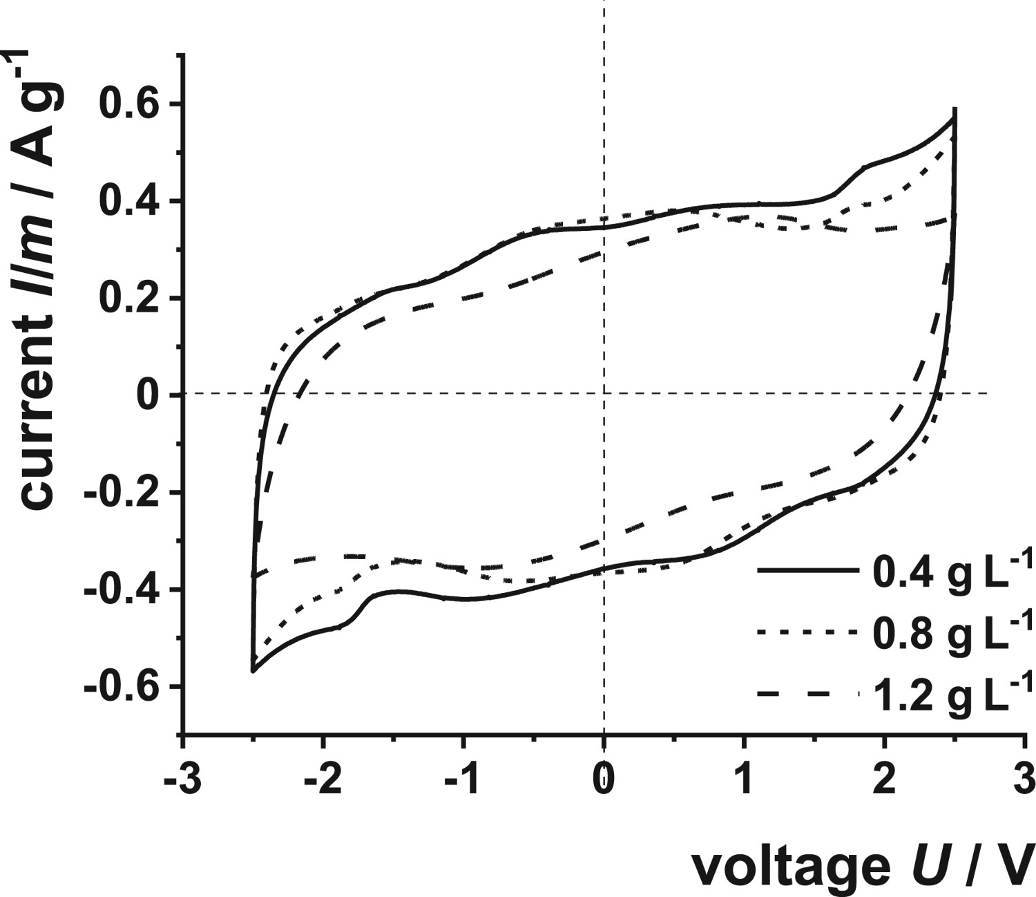
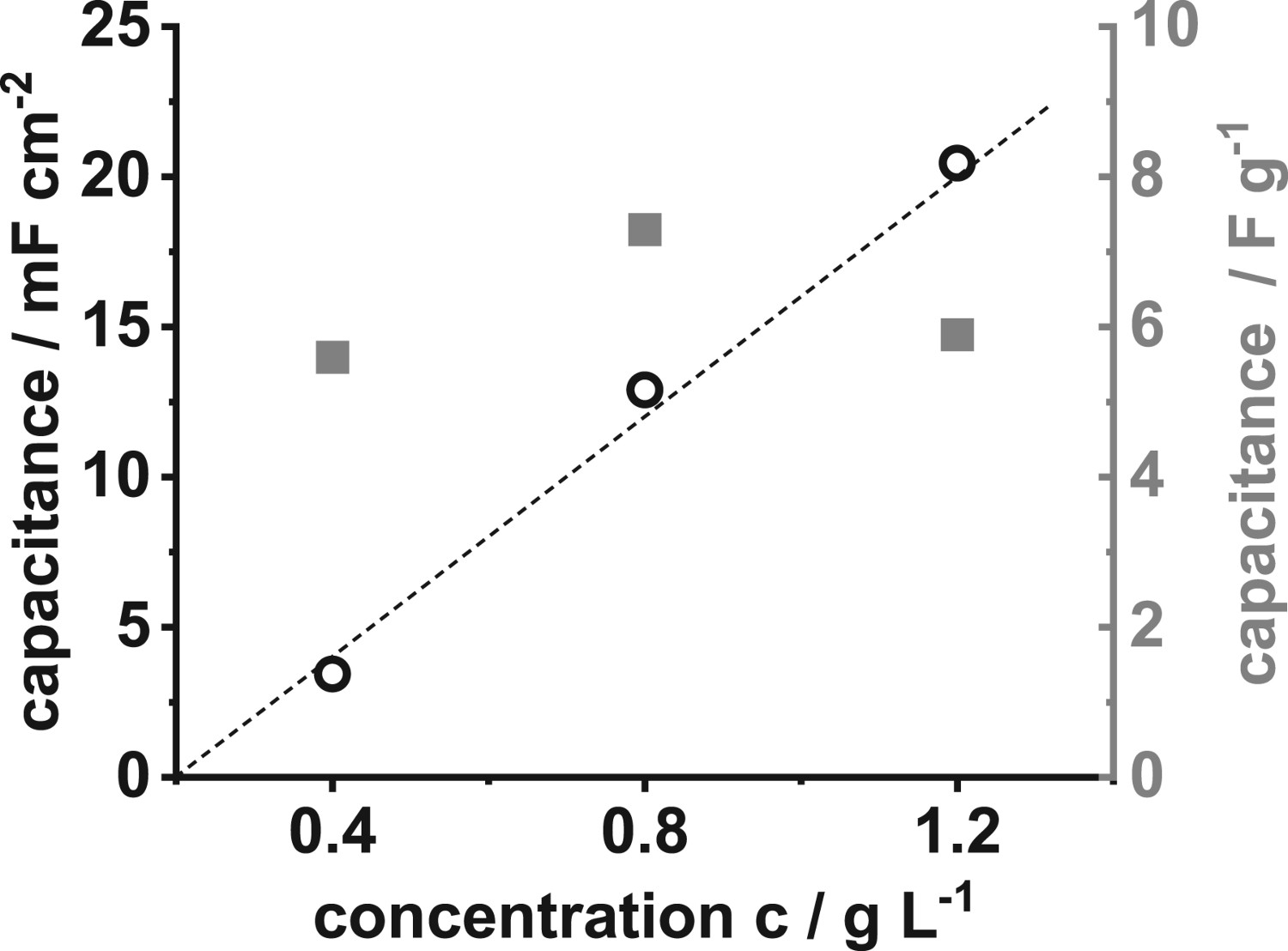
A critical evaluation of the presented results seems to be appropriated. In the almost unmanageable number of publications regarding carbon and their application as double-layer capacitors, the reported data greatly vary. Zhang et al. [38] reported about C = 13 F g−1 and Pandolfo et al. reported up to 90 F g−1 in their useful review [39]. Boccacini et al. reported specific capacitances of CNT between 4 and 147 F g−1 [40]. Unfortunately, the comparability is difficult due to the different methods used to determine the capacitance [41], or not exactly reported as when Inagagki et al. [42] complain about the lack. For example, the measured capacitance and the normalized capacitance differ by a factor of four [26]. Nevertheless, the achieved capacitance in the present papers is comparatively small (Figure 13). It should be possible to improve the capacitor performance by additional treatment of the MWCNT, e.g. heat treatment [43] or electrochemical treatment [44] to enhance the specific surface area, tuning the pore size distribution and increasing the electronic conductivity. Moreover, the EPD process offers the possibility for further modification, wet-in-wet using, e.g. transition metal oxides to create an additional pseudo-capacitive part.
Conclusion
The present work focuses on a facile and environmentally friendly technology to form EDLC on the base of MWCNT. Based on the experimental results, the following findings are obtained:
The CCCC are found to be suitable and stable electrodes for the EPD of MWCNT. A degradation of the carbon coating during the EPD was not observed. The carbon coating does not hinder the EPD of the MWCNT. The kinetics of the deposition follows the theoretical expectation expressed by the Hamaker equation. The deposition rate at U = 50 V is about 0.03 mg cm−
2 min−1. The carbon coating prevents the anodic oxidation of the aluminium substrate in the aqueous suspension, which is a prerequisite that the MWCNT layer can act as EDLC. The gravimetric capacitance obtained was about 8 F g−1.
Footnotes
Disclosure statement
No potential conflict of interest was reported by the author(s).