
Abstract
An attempt was made in this study to coat Hastelloy with copper carbide utilizing an electric discharge alloying process. Experiments were carried out in such a way that materials were initially removed from the surface, but after a prescribed time in the absence of flushing, it was coated on the surface. Experiments were conducted by varying copper powder concentration, current, pulse on time, and gap distance and experimental runs were designed using the Taguchi mixed orthogonal array. Pure dielectric medium materials were removed from the surface, at 5 g l−1 PMEDM material removal followed by deposition occurred, beyond 10 g l−1 PMEDM condition, only material deposition was observed. Surface topography revealed that the cracks formed on the coated surface with an increase in Cu concentration get intensified and penetrated the base material. The hardness and wear resistance of coated samples are enhanced owing to the presence of harder carbide particles and mechanically mixed layer formation. The mode of wear was adhesive and abrasive for the uncoated and coated samples.
Introduction
Hastelloy C276 found its application in heat exchangers and nuclear reactors owing to its exceptional corrosion resistance and excellent mechanical properties at elevated temperatures. The hardness and tensile strength of Hastelloy were measured as 88HRB and 601 MPa, respectively, making it extremely difficult to process in the conventional machining technique [1]. Ultrasonic machining, abrasive-water jet machining, laser beam machining, plasma arc machining and electric discharge machining (EDM) were some of the distinct unconventional processes utilized for cutting tougher materials [2-4]. Of the various machining techniques, EDM produces components with high precision and accuracy [5] and is suitable for hybrid processing [6]. The anti-bacterial coating on the Hastelloy surface of heat exchangers inhibits bacterial adhesion [7]. Chemical vapour deposition, electroplating, physical vapour deposition, lithography, ion implantation and thermal spraying were the different techniques used for the surface modification [8]. However, all of these approaches need expensive equipment, which raises the price of the product [9]. Hence to overcome it, hybrid processing in EDM, i.e. machining cum coating was a feasible option.
EDM can be exploited to modify surfaces, and the process was known as electric discharge alloying (EDA). In EDA surface modification was attained by four methods [10]. When a green compact electrode manufactured by powder metallurgy was utilized as the tool material, materials from the tool materials were migrated to the workpiece surface owing to slackening inter-particle bonding [11]. Instead of a rigid material electrode, a lot of thinner cross-section coating material electrodes were heaped together to produce a big cross-section electrode in the wire brush approach. This pile of electrodes was used for the coating process [12]. Powders of high concentration were incorporated in the dielectric fluid, when subjected to high temperature, they react with carbon present in the dielectric fluid and coated over the substrate [13]. Materials were deposited on the substrate when solid electrodes were connected to the negative polarity [14]. Manufacturing green compact and wire brush electrodes was a time-consuming and expensive process. In the current study, surface modification was accomplished by incorporating powder particles into the dielectric fluid and connecting the tool to the cathode.
Current, pulse on time (Ton), polarity, gap distance, pulse off time (Toff), powder concentration and flushing pressure are the important process parameters that influence the deposition of materials over the substrate [15-17]. The rate of material deposition on the surface increases as the current and Ton increase, because it produces a high-intensity spark and the generated spark is held inside the machined gap for a longer time, removing a large volume of tool materials and depositing them over the machined surface but tuning parameters beyond the threshold limit results in deeper void [18,19]. A thin electrode can be used to deposit a coated layer while keeping the powder concentration high, but a gear-shaped spinning electrode can deposit a larger area with uniform thickness [20]. The thickness of the coated layer depends on the concentration of powder in the dielectric fluid [21]. More electrons and ions are generated by energized powder particles and the spark hits at a larger gap distance [22]. The elements, namely carbon, copper, and tungsten, were deposited over the aluminium when machined in a tungsten powder mixed kerosine dielectric medium [23]. When titanium powder was suspended in the hydrocarbon oil, it reacts with discharged carbon elements and was deposited as titanium carbide on the substrate [24]. The combination of carbon and suspended particles facilitates strong metallurgical bonding, grain refinement, and exceptional mechanical properties with high temperature wear resistance [25]. PMEDM improved migration and proliferation, resulting in an alloy surface with bioactivity and biocompatibility [26]. From the above literature survey, it was clear that several researchers attempted to modify the surface through the EDA process by incorporating powder in the dielectric medium. Works related to the coating of Hastelloy by incorporating copper powder in the dielectric medium were scarcely available. In this research, copper particles were included in the dielectric medium to coat the Hastelloy with copper carbide to improve the mechanical property and biocompatibility. Experiments were conducted in such a way that initially materials were removed from the Hastelloy, followed by material coating, which was a novel approach. Investigations were made on the deposition of C2Cu2 and evaluating its properties, such as surface roughness, microstructure, hardness and wear resistance.
Materials and methods
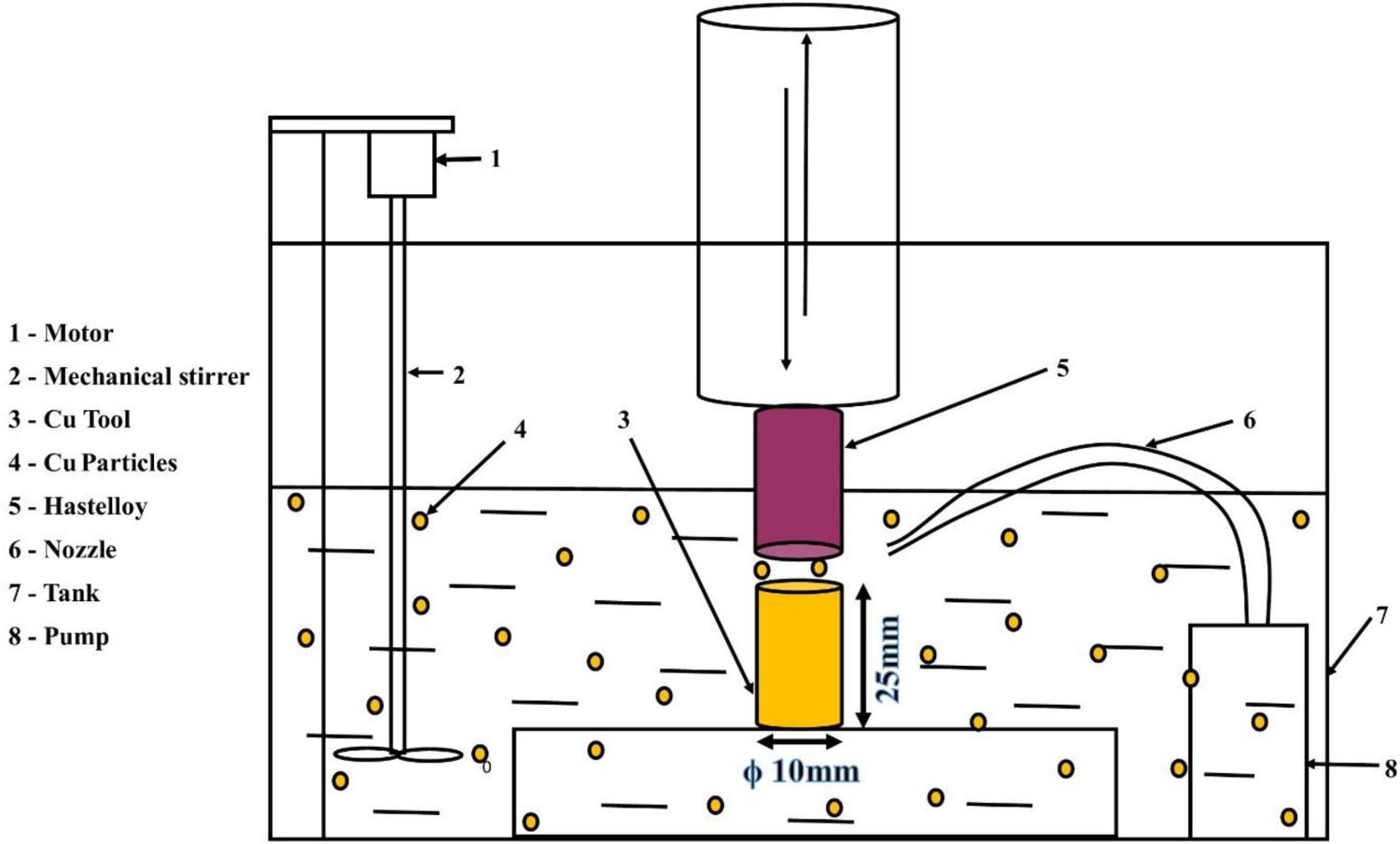
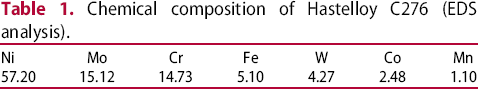
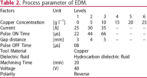
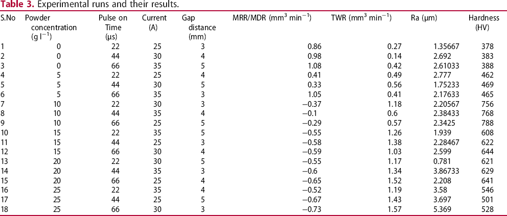
Hastelloy C276 of dimensions (L – 150 mm × ϕ – 10 mm) was procured from the Shubham industries having the chemical composition, as depicted in Table 1, was selected for investigation and the experimental set-up is shown in Figure 1. Experiments were conducted by varying copper powder concentration, current, Pulse on Time (Ton), and gap distance, with experimental runs designed using a Taguchi orthogonal array. The EDM process parameters are shown in Table 2. Throughout the experiment, negative polarity was maintained by connecting a solid copper rod to the cathode and Hastelloy to the anode. The specimens were machined for 15 min and machining performance was accessed in terms of Material Removal Rate (MRR), Tool Wear Rate (TWR) and Surface Roughness (Ra). Followed by it, the dielectric fluid flushing pump was switched off for 5 minutes to facilitate the coating of C2Cu2 over Hastelloy. As the pump was switched off for the last 5 min it caused densification of machined debris in the spark gap. As the copper was connected to the cathode, a higher volume of materials eroded from it and migrated to the anode, deposited over the Hastelloy that was connected at the negative terminal, which was referred to as the Material Deposition Rate (MDR); in this case, the weight of the workpiece before machining was higher than the weight after machining. The weight difference before and after machining was obtained using 0.0001 g precision electronic weighing machining. The ratio of the weight difference to the product of density and machined time was taken as MRR and TWR, as shown in Equations (1) and (2), respectively. The Ra
was obtained using the SJ210 surface roughness tester, and the average value from 10 places was documented as the Ra
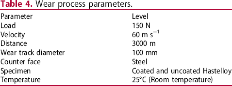
. The experimental results are depicted in Table 3. The properties of the coating were evaluated in terms of SEM with EDS mapping, EDAX, Vickers hardness and wear resistance. Vickers hardness tests were done on the specimens based on ASTM E384 standards, and wear tests were performed using pin-on disc apparatus in accordance with ASTM G99 – 05 standards. The wear test parameters are shown in Table 4. The worn surface morphology was analyzed with the aid of SEM.
Experimental set-up of electric discharge alloying. Chemical composition of Hastelloy C276 (EDS analysis). Process parameter of EDM. Experimental runs and their results. Wear process parameters.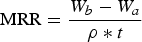
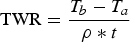
Tb & Ta – weight of the tool before and after machining
ρ – Density of the material
t – Machined time
The unit of MRR and TWR was mm3 min−1.
Results and discussion
Influence of various process parameter on MRR
The impact of various process parameters on the MRR of Hastelloy is depicted in Figure 2. MRR decreases as powder concentration increases and MRR shifts to MDR as powder concentration increases from 5 to 10 g l−1. When the powder concentration was more than 15 g l−1, no discernible increase in MDR was observed. From the results, it was confirmed that the optimal powder concentration for coating C2Cu2 was 15 g l−1 but no machining occurs. On the other hand, MRR at 5 g l−1 PMEDM was 65% lower than that of unmixed EDM condition. Nominally when foreign particles were incorporated into the dielectric fluid, MRR increases because of the bridging effect, as reported by several researchers [27-29]. Hence it was confirmed that when the flushing was turned on, the material was removed, it was turned off, it was coated over the surface, connected to the negative polarity at 5 g l−1 powder concentration. Hereon the machining characteristics were categorized into two different phenomena, Category A – machining performance at a copper concentration less than 5 g l−1, Category B – machining performance at a copper concentration greater than 5 g l−1. In category A, as the generated heat was held inside the spark gap for an extended time, the MRR increased with the rise in Ton. As a result, a large volume of materials was eroded and removed. In category B, owing to the higher concentration of Cu powder, machined debris densification occurred. Owing to this even at the flushed condition, materials were not completely eradicated. Because of its high thermal conductivity, Cu particles absorbed heat, melted and deposited over the machined surface, and the MDR rate increases with an upsurge in Ton.
Impact of various process parameters on MRR of Hastelloy.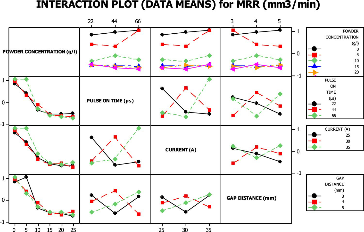
With an increase in current, it creates very high-intensity sparks, which removes a larger volume of material [30], resulting in an increase in MRR for Category A. When high concentrations of Cu powders were added, plasma widening occurs for higher parametric values of current, resulting in a reduction of discharge intensity and MDR. When machined in a pure dielectric medium, with a raise in gap distance machined debris was completely flushed away, which facilitates the increment of MRR. It was evident from the data that no coating transpired without the addition of powder particles. In the case of 5 g l−1 PMEDM, MRR reduces with a rise in the spark gap. At 5 mm gap distance and flush off condition, a higher volume of materials accumulated inside the machined gap, with the applied voltage these materials liquefied and deposited over the machined surface. Hence machining characteristics were further classified into (i) Category A1 – only machining occurs under pure dielectric medium and (ii) Category A2 – machining cum coating occurs at a 5 g l−1 copper incorporated medium. In category B, MDR increases when the gap distance augments owing to the accumulation of a greater volume of materials, as previously discussed.
Influence of various process parameter on TWR
The influence of distinct process parameters on the TWR is depicted in Figure 3. Phenomenally more volume of material was removed from the specimens connected to the negative terminal. This was owing to high-velocity discharged electrons colliding with the anode surface in a split second, generating a tremendous amount of energy and triggering anodic material melting and rapid vaporization [31,32]. The TWR increases as the powder concentration increases, with the lowest TWR observed, when machined in an unmixed dielectric medium. When the voltage is applied, suspended particles move in a zigzag pattern and bridge the space between the tool and the electrode [33]. It decreases the dielectric fluid's insulating strength, causing sparks to occur more often, which raises TWR with an increase in powder concentration. The objective of removing high tool material to facilitate the C2Cu2 coating on the Hastelloy was attained, as evidenced by the MRR experimental results at high powder concentration levels. In TWR no categorization was observed because in all the cases material was removed from the surface.
Impact of various process parameters on TWR.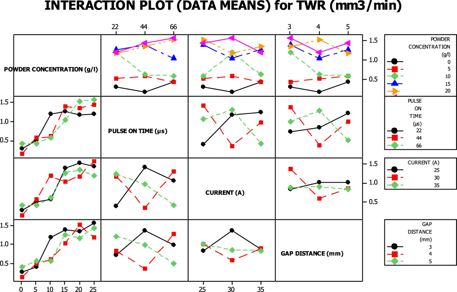
TWR increases with the increasing current in an unmixed dielectric medium because a high current produces a high-intensity spark, which removes a large volume of materials. With the addition of foreign particles, the spark occurred more frequently, owing to which at the higher parametric level of the current expansion of plasma channel occurred, which reduces the heat intensity and TWR. When the Cu powder of concentration of more than 20 g l−1 was added TWR increases with the rise in Ton and reaches the maximum of 1.57 mm3 min−1 for 66 µs Ton. In PMEDM at higher concentrations TWR reduces owing to the machined debris densification. According to the findings, even though more tool materials were removed from the surface at higher parametric levels, there was no effect on MDR. It was confirmed that coating was not feasible after a specific layer thickness. Maximum TWR was attained when the gap distance was maintained at 3 mm. Because of the small range between the tool and the electrode, higher heat intensity was achieved, increasing the TWR.
Influence of various process parameters on Ra
As the workpiece was connected to the cathode, a low-intensity spark hit the surface, causing the Ra value to decrease, as shown in Figure 4. The Cu powder concentration has very little impact on the Ra, as the flat line was observed till the concentration of 20 g l−1. Unmixed dielectric medium has a Ra of 2.21 µm, which rises slightly to 2.31 µm at 20 g l−1 powder concentration. But when the Cu concentration was increased to 25 g l−1, the Ra value drastically increased to 4.21 µm. Uncontrollable discharges of higher forte were generated at higher concentrations, lowering the surface quality. The surface quality was categorized into machined surface roughness (Ra), material deposition roughness (Rb) and machined cum deposition roughness (Rab). Ra rises as the current increases because it produces more intense sparks [34], which create cracks and craters on the machined surface, lowering the quality of the machined surface. In the case of Rb
and Rab
, the best surface quality was attained when machined at the current of 30 A, and with further increase worsens the surface quality owing to plasma densification. Because of the uncontrolled fortes, the quality deteriorates to a greater extent at the powder concentration of 25 g l−1.
Impact of various process parameters on Ra of Hastelloy.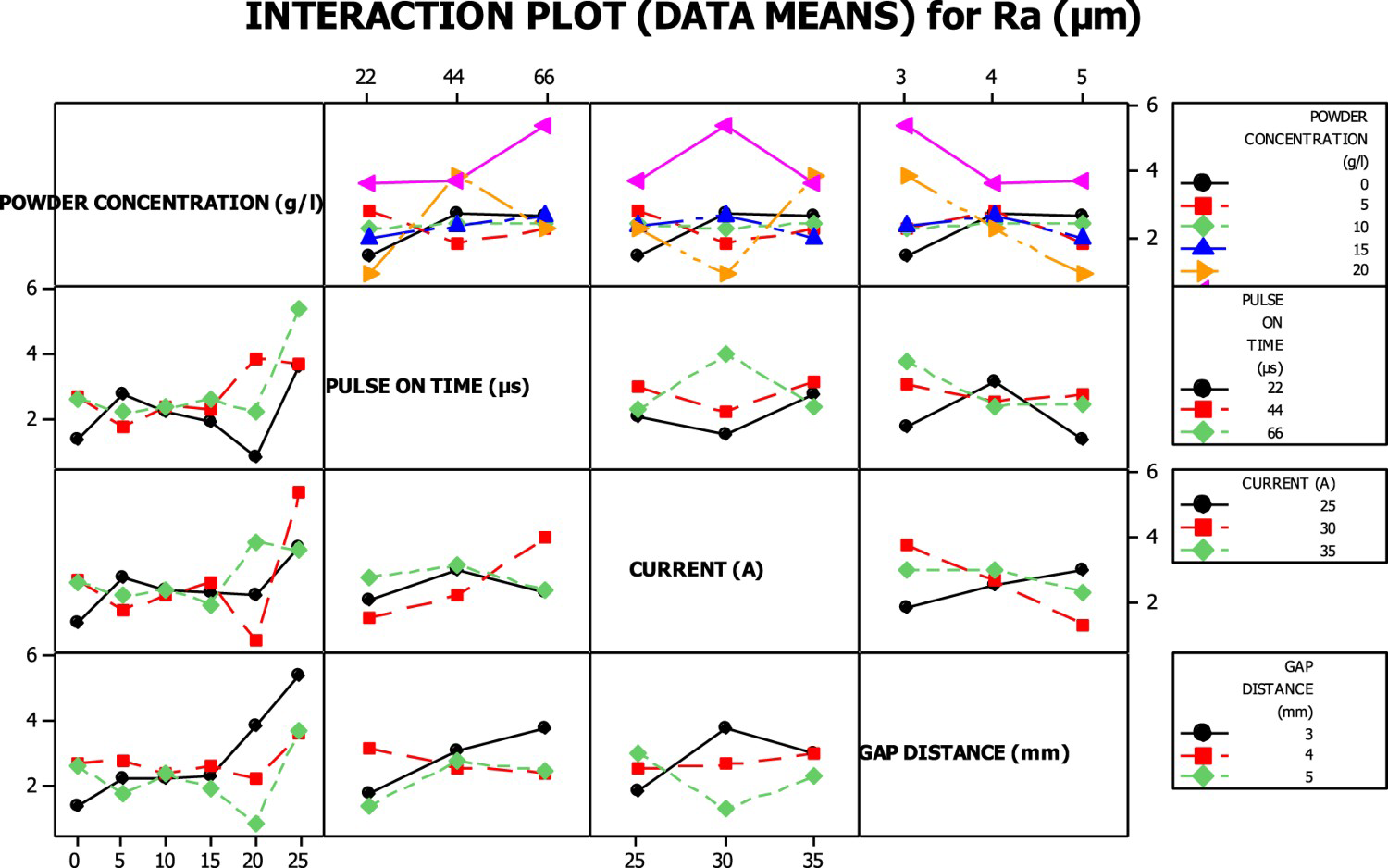
The Ra increases with an upsurge in Ton because of machined debris densification. The machined debris was not entirely flushed away as a result, and some of the particles resolidified on the surface, lowering the surface quality [35]. When it pertains to Rb and Rab , better quality was attained when machined at a Ton of 44 µs. Owing to a large amount of energy created, the electrolytes undergo pyrolysis, which results in a thin coating of carbon being formed on the cathode surface, shielding it from the compressive shock waves caused by the collapse of sparks [36]. With a further increment in Ton, this shielding breaks down, hence surface quality worsens. Ra reduces with an increase in gap distance as it facilitates the complete flushing of machined debris. The value of Rb depends on the dielectric strength of the insulation fluid and in most circumstances minimum, Rb was attained for a 4 mm gap distance.
Machined surface morphology
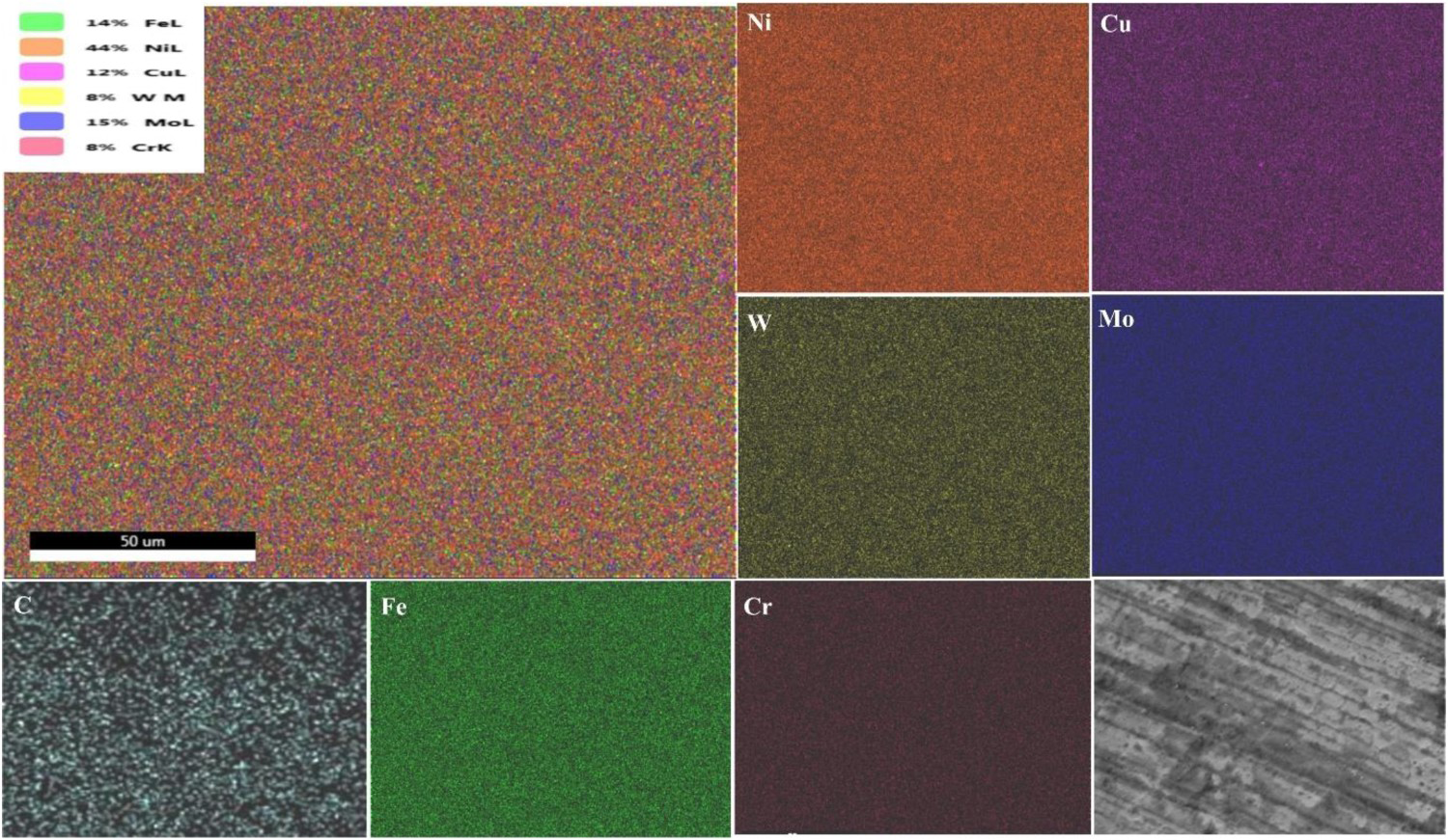
The material deposition over the machined surface was analyzed through SEM with EDS mapping. For the investigation, specimens machined in 5 and 10 g l−1 dielectric medium were chosen. As previously stated, the dielectric medium that provides machining cum coating and the optimum coating was selected. At the 5 g l−1 dielectric medium, the complete surface coating was not achieved; instead, it was coated in the pattern of the incorporation of reinforced particles in composite materials, as shown in Figure 5. In addition to the alloying elements, Cu and C were observed on the machined surface, as analyzed with EDAX mapping. The Cu element was deposited from the incorporated powder particles. During machining, dielectric fluid was subjected to a high temperature, resulting in decomposition and discharge of carbon atoms, which react with copper and are deposited on the surface as C2Cu2. When the Cu concentration in the dielectric fluid was increased to 10 g l−1, the machined surface was completely coated by the C2Cu2, as depicted in Figure 6. In both cases, the chemical composition of the Cu and C elements was observed to be higher than 20%.
EDS mapping of Hastelloy machined at a 5% Cu-incorporated dielectric medium. EDS mapping of Hastelloy machined at a 10% Cu-incorporated dielectric medium.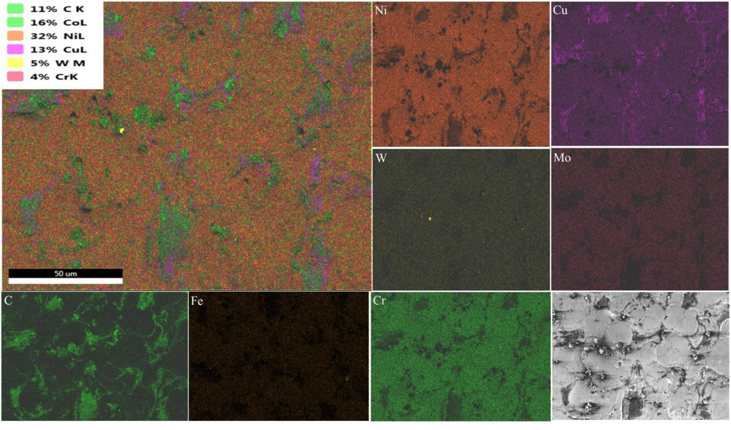
EDM is a method of machining that involves melting and vaporization. The requisite heat generated by a spark that impacts the surface, creates craters and cracks, as shown in Figure 7(a) when machined in an unmixed dielectric medium. The topography showed black spots, which was the deposition of the discharged carbon atom from the dielectric fluid. The dielectric fluid decomposed and discharged carbon atoms as the machining time prolonged. These carbon atoms are deposited on the tool, lowering the spark intensity. Hence, materials that were boiled on the surface result in the formation of the material dunes as observed in the surface topography. At higher magnification, micro-cracks, craters, globules and resolidified materials were visible on the surface topography, as depicted in Figure 7(b). Owing to the inadequate flushing, materials removed during the process were resolidified and deposited over the machined surface as the globules and the resolidified materials. The globules mimic the shape of the machined debris.
Surface topography of Hastelloy machined at a pure dielectric medium (a) At 100X (b) At 500X.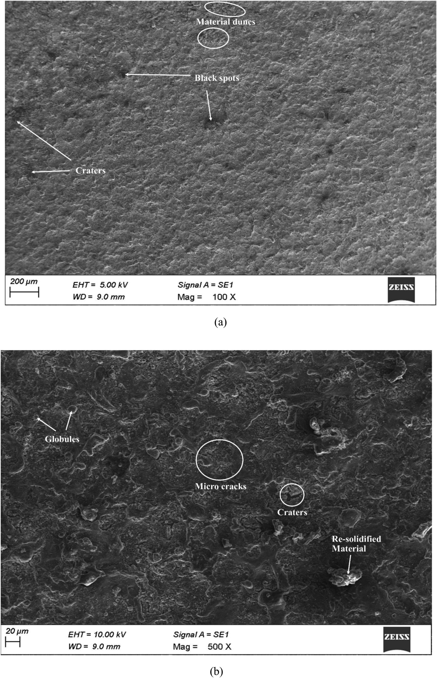
When the concentration of particles in the dielectric fluid was increased to 5 g l−1, agglomeration of coated particles was spotted all over the surface, as shown in Figure 8(a). The coating appeared in patches, with crater valleys evident at the boundaries of the patches. The globules resembled elongated orbs, which evidenced that shape of the machined debris changed with the addition of powder particles. At higher magnification material dunes and resolidified particles were clearly visible on the machined surface, as depicted in Figure 8(b). Micro-cracks were observed on the coated surface and the approximate area of the uncoated surface was computed to be 8 × 103 µm2. Interestingly cracks, craters and pits were not observed on the uncoated machined surface.
Surface topography of Hastelloy machined at a 5% Cu-incorporated dielectric medium (a) At 100X (b) At 500X.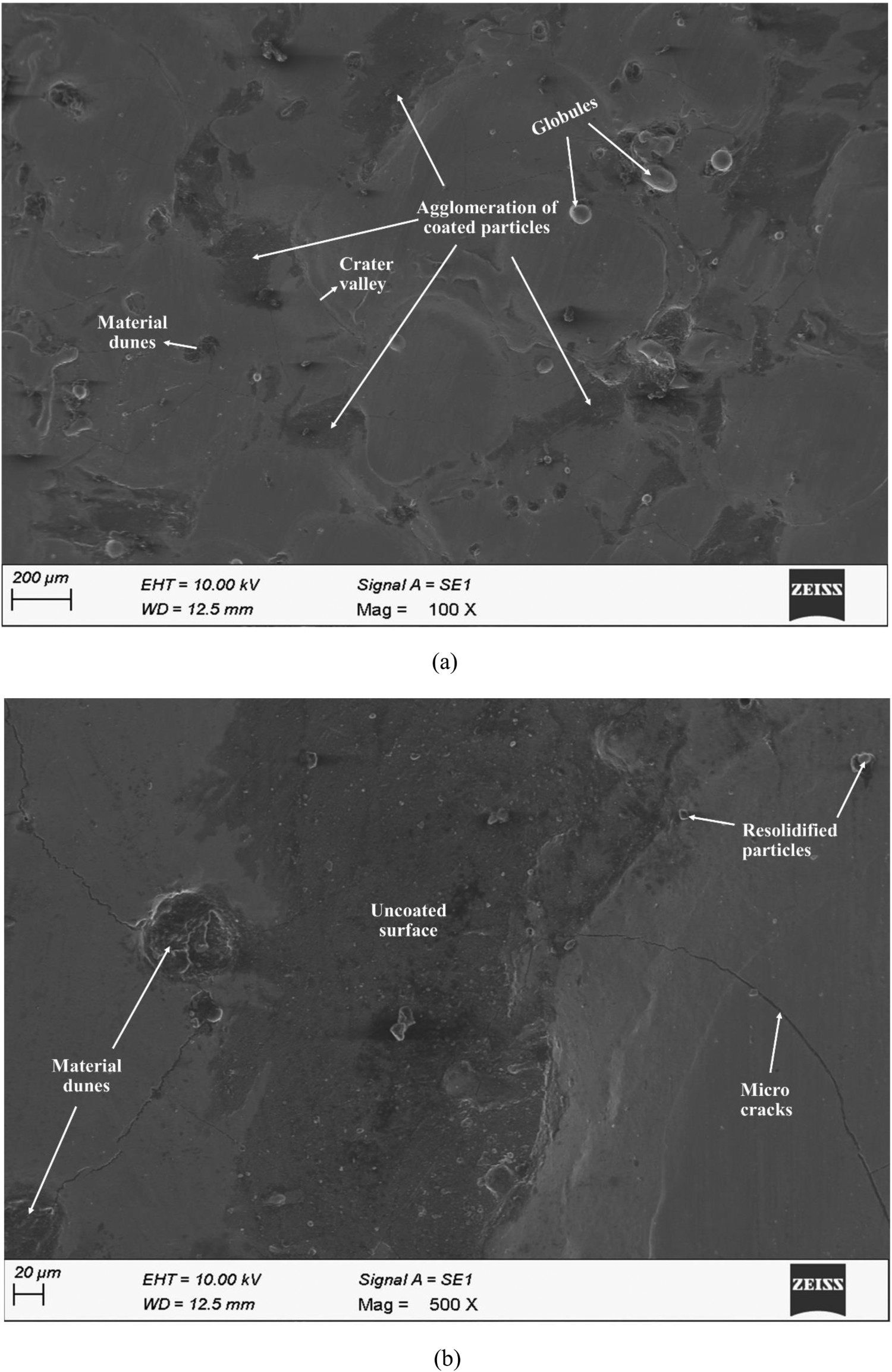
When machined in a 10 g l−1 Cu incorporated dielectric medium, the topography showed materials dunes and resolidified layer, as depicted in Figure 9(a). The material dunes confirm the carbon coating over the tool materials. The quantity of resolidified layer formed on the surface was very low, in comparison with machined in a pure dielectric medium. Although some aggregation of coated particles was observed, the machined surface was entirely coated with C2Cu2. The coated layer has surface cracks that start at the surface and move perpendicularly towards the interferential zone. The area of the uncoated machined surface was ciphered as 1 × 103 µm2. At higher magnification, the topography showed resolidified materials and cracks, as shown in Figure 9(b). The length of the crack ranges from 200 to 300 µm, which demotes the quality of the coated material.
Surface topography of Hastelloy machined at a 10% Cu-incorporated dielectric medium (a) At 100X (b) At 500X.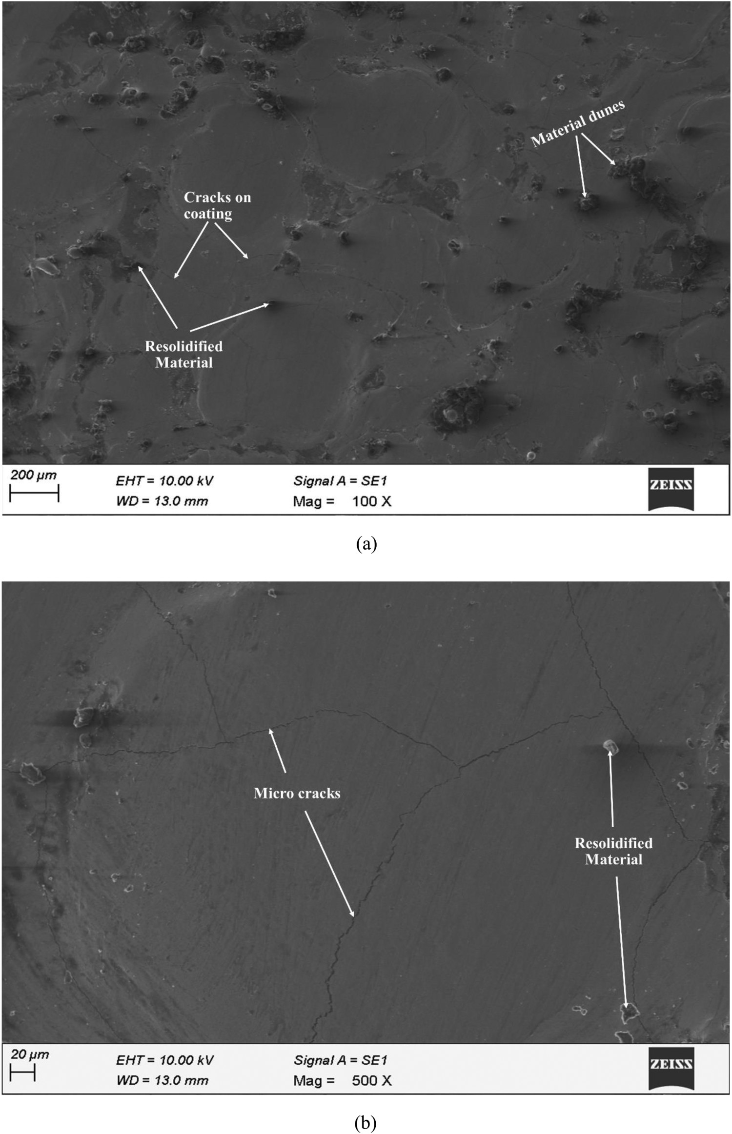
Identical machined surface topography was observed when machined in the 15 and 20 g l−1 Cu powder incorporated dielectric medium. Coating occurred in patches, and the integrated particles coated the entire machined surface. Globules and the material dunes were the features visible on the surface, as depicted in Figure 10(a). As discussed, crater valleys were observed on the borders of the coated patches. At higher magnification, cracks were clearly visible on the coated surface. The intensity and width of the crack were higher than that of cracks that appeared on the surface coated with a 10 g l−1 incorporated dielectric medium. The crack has an uneven shape and can be observed on the crater rims. The topography also revealed some of the resolidified material on the machined surface, as portrayed in Figure 10(b).
Surface topography of Hastelloy machined at a 15% Cu-incorporated dielectric medium (a) At 100X (b) At 500X.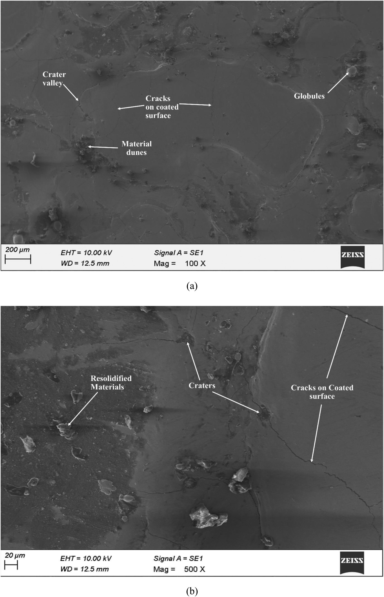
At a higher concentration of 25 g l−1, a novel feature known as a black hole was spotted on the surface, as seen in Figure 11(a). Its pits formed during machining and were filled with carbon atoms, providing it the appearance of a black hole. Owing to the inadequate flushing, globules were revealed on the surface along with the agglomeration of coated particles. The surface was coated in patches, with the uncoated machined surface surrounding the coating. At higher magnification cracks were visible on the coating and on the uncoated machined surface. The crack was formed on the coated material and penetrated deep into the parent material. As portrayed in Figure 11(b) globules and craters valleys were clearly visible on the surface. The micrograph confirmed that the Hastelloy was coated with C2Cu2 but in all the parametric combinations cracks were formed on the coated surface. With an increase in the concentration of powder particles the intensity of the spark increased and at higher concentrations penetrated inside the base metal.
Surface topography of Hastelloy machined at a 25% Cu-incorporated dielectric medium (a) At 100X (b) At 500X.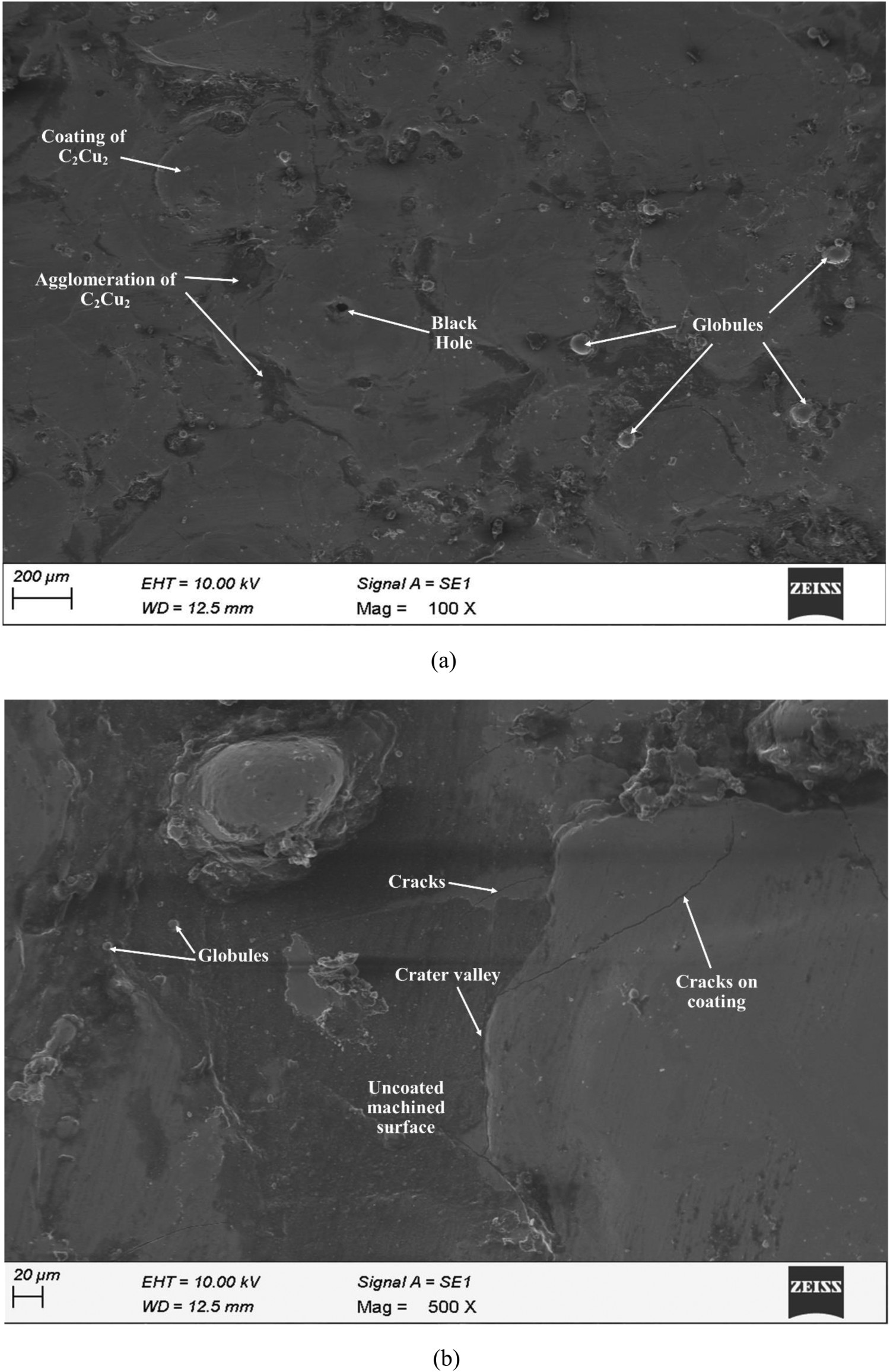
Hardness
The mean Machined Surface Hardness (MSH) of the specimen machined in a pure dielectric environment was 383HV and it was increased to 770HV when 10 g l−1 of Cu powder particles were incorporated into the dielectric fluid. The harder C2Cu2 coating on the machined surface was responsible for the increase in hardness value [37]. With a further increase in the concentration of Cu powder in the dielectric medium the hardness value decreases owing to the following factors. (i) Owing to alloying element dispersion, EDC hardness varies randomly across the coating, with more deformation occurring near cracks and sludges. (ii) Coating governs the dispersion of alloying elements and appropriate compositions result in high hardness values. (iii) A densely packed carbon element has better resistance to hardness, but an amorphous carbon element exhibits plastic deformation, which determines the hardness of copper carbide molecules. At a 5 g l−1 incorporated dielectric medium, the specimen exhibits lower hardness owing to the coated particle agglomeration.
Wear
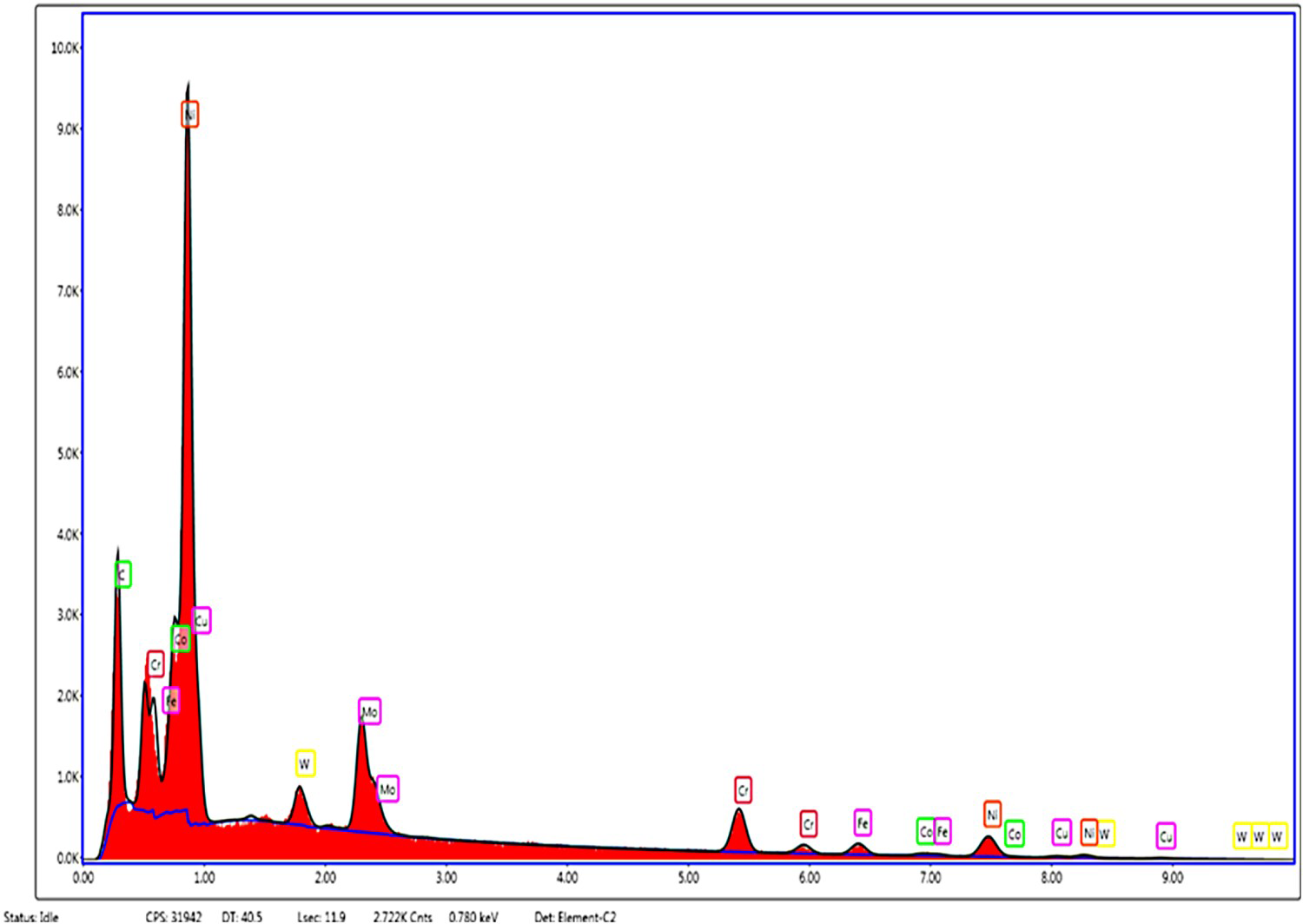
The wear rate was expressed in terms of mm3 min−1 and specimens coated with C2Cu2 exhibited a lower wear rate in comparison with uncoated samples, as depicted in Figure 12. The enhancement in wear rate was attributed to the fact that the copper particles dispersed in the dielectric fluid migrated to the surface as the harder C2Cu2. According to Archard law, material that possesses high hardness offers high resistance to the wear rate [38,39], which was well correlated with the experimental results. When coated sample slides, C2Cu2 abrades the material from the counter face, resulting in the formation of a Mechanical Mixed Layer (MML). This MML prevents direct metal contact and hence reducing the wear rate [40]. With prolonged sliding time, this MML breaks down, resulting in abrasive wear [41]. The presence of Fe in the EDAX analysis confirms the formation of MML, as shown in Figure 13. The composition of Fe element in the base alloy was 5.1%, which was raised to 14% on the worn surface. When it pertains to the wear of coated samples, the only difference was the rate at which it occurs, yet all samples have comparable wear. Wear was identical under the same loading conditions, as the debris was formed because of micro-abrasion, when the carbide accumulated over the nickel.
Wear of coated and uncoated Hastelloy. EDX analysis of the worn surface.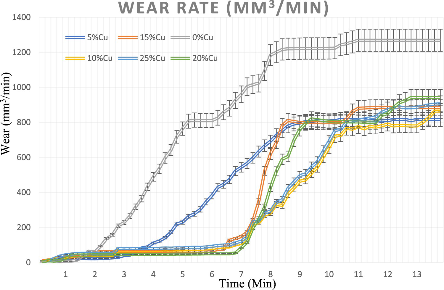
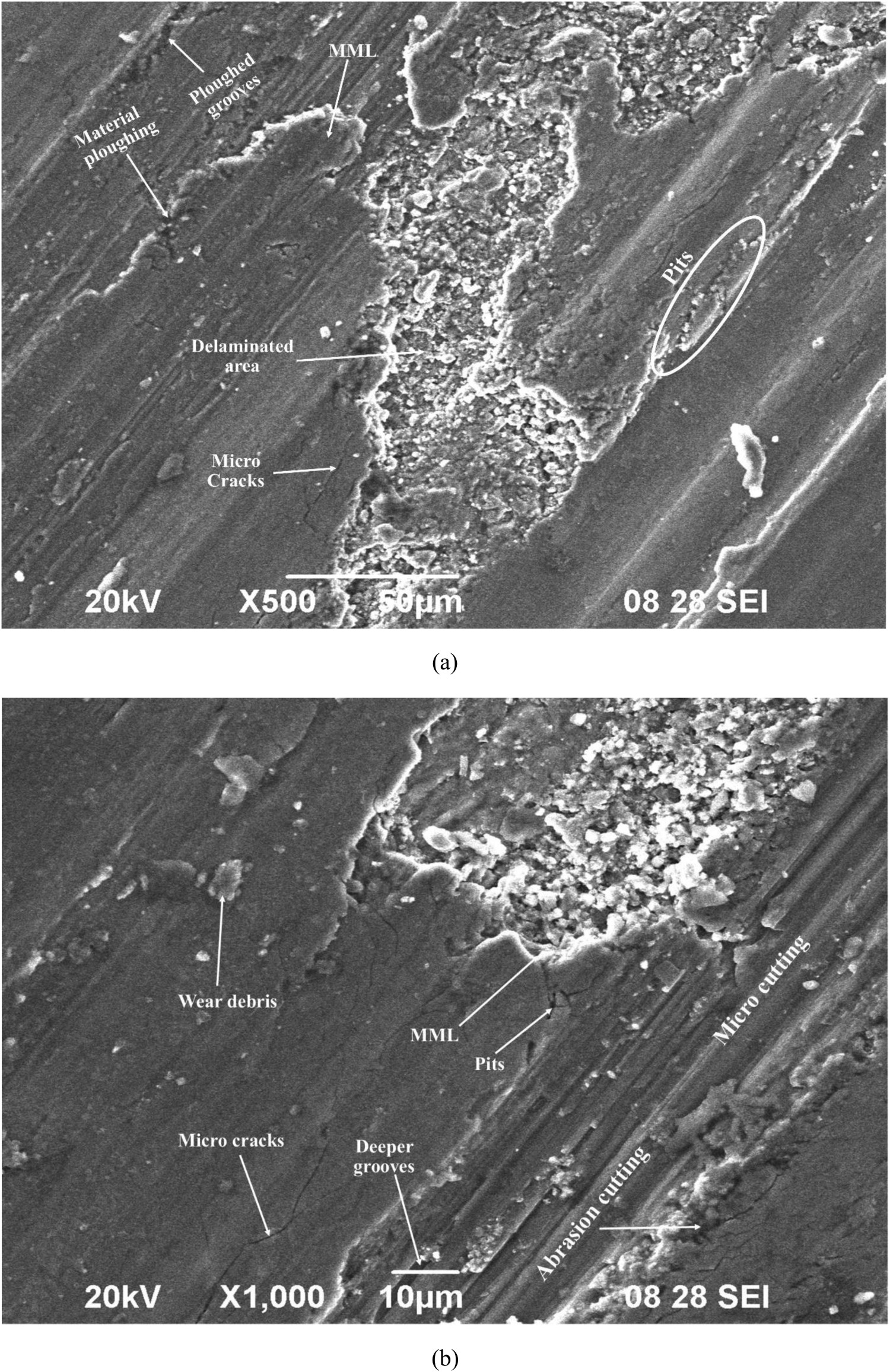
The worn surface of coated and uncoated samples was examined using an SEM to analyze the wear mechanism. When the uncoated samples were slid at the prescribed load and velocity, the wear occurred by micro-cutting, as shown in Figure 14(a). The materials were plastically deformed and flowed in the sliding direction. Some of the debris was reattached to the surface, confirming that the material reaches its deformation temperature while sliding. At higher magnification, materials were ploughed from the surface and the edges of ploughed surface were blended, as shown in Figure 14(b), which confirms the absence of abrasion cutting. The size of the worn debris ranges 6–7 µm and was ovaloid. When the coated samples were slided, owing to the abrasion of the pin and disc, MML was formed. When these layers break down resulted in delamination wear, as portrayed in Figure 15(a). Micro-cracks and micro-pits were observed on the worn surface morphology. The edges of the delamination area were sharper, indicating that abrasion was the mode of wear. At higher magnification, micro-grooves, deeper pits and micro-cracks were observed on the surface, as shown in Figure 15(b). The size of the worn debris varies from 4 to 5 µm and wear occurred by means of abrasion and micro-cutting. Materials were ploughed out as a result of abrasive wear, abrasive grooves and scratches were clearly visible.
Worn surface morphology of Hastelloy machined in a pure dielectric medium (a) At 500X (b) At 1000X. Worn surface morphology of Hastelloy machined in a 10% Cu-incorporated dielectric medium (a) At 500X (b) At 1000X.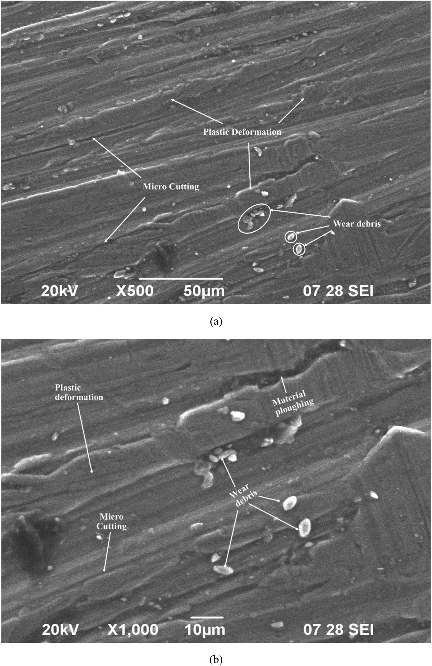
Conclusion
When connected to the reverse polarity, machining in the Cu-incorporated dielectric medium occurred in three categories. Only MRR, MRR cum MDR at 5 g l−1 and MDR above 10 g l−1 Cu mixed dielectric medium. The optimal MDR was attained by incorporating 10 g l−1 of Cu particles into the dielectric fluid; subsequent increases in concentration have no effect on MDR. TWR increases with an increase in the concentration of Cu powder because of bridging effect, in some cases, it was higher than the MRR. MDR was unaffected even when more tool materials were removed from the surface at higher parametric settings, which confirmed that coating was ineffective after a certain layer thickness. The concentration of Cu powder has a very minimal impact on the Ra of the Hastelloy. At higher powder concentrations, uncontrollable discharges of higher intensity were generated, causing damage to the surface quality. The best surface quality was attained when the current was tuned at 30A, and increasing it further increases the Ra owing to plasma densification. The coating of C2Cu2 was confirmed through EDAX mapping and agglomeration of coated particles occurred at 5 g l−1, whereas the surface was completely coated at 10 g l−1 dielectric medium. Cracks on the coated surfaces, craters, globules and resolidified materials were the distinct features observed on the machined surface topography. With an increase in Cu concentration, cracks on the coated surface intensified and penetrated inside the base material. The hardness and wear resistance of the coated samples improve as a result of the deposition of harder carbide particles and the formation of MML on the surface. Abrasive wear was evident on the coated surface, whereas uncoated specimens were worn owing to micro-cutting.
Footnotes
Disclosure statement
No potential conflict of interest was reported by the author(s).