
Abstract
In the current work, single and multi-level micro-texturing on Ti–6Al–4V surfaces was performed through electrical discharge micromachining. The wetting properties of the single-level features obtained through EDMM have been studied, which revealed a higher water contact angle (CA) of ∼110° with respect to an untextured surface (water CA ∼38°). The concept of dimples overlapping (% of overlap between adjacent dimples) has been adopted to propose a novel technique for the simultaneous machining of multiple micro-features through a simpler cylindrical tool electrode, which otherwise necessitates multi-step fabrication or preformed tools. Adopting the proposed concept, multi-level textures consisting of micro-dimples surrounded by micro-pillars were machined on the Ti–6Al–4V surface. With multi-level textures, the water CA increases significantly compared to the untextured surfaces. The maximum water CA ∼ 104.2° was obtained with a 300 µm diameter tool and 25% dimple overlap, thereby rendering the surface hydrophobic.
Introduction
Over the years, there has been a pursuit for modification in the surface characteristics of commonly used materials to obtain the required properties. The researchers have explored surface topography alteration via. micro/nano-patterns [1] and the application of appropriate coatings. Recent studies reported a considerable enhancement in anticorrosive and tribological properties of Cr-based coatings [2-5], while surface texturing over a large area to obtain several exceptional functionalities is another method to produce engineered surfaces. Textured/engineered surfaces offer numerous advantages over untextured surfaces of the same material, which include an increase in hydrophobicity for water repellence, hydrophilic surfaces for biological applications (tissue growth and protein adhesion), corrosion resistance, heat transfer enhancement, anti-icing or self-cleaning properties, drag reduction, cutting tool performance improvement, etc.[6,7]. Micro-texturing can be done using a variety of methods in the material subtraction regime besides material addition methods [8]. Among the material removal methods of surface texturing, advanced machining processes (AMPs) along with conventional machining processes have been utilized. Laser surface texturing (LST) has successfully been implemented for micro-dimples array machining on the inner cylinder of an automobile engine, which resulted in reduced friction and wear of the cylinder inner liner due to lesser contact between the piston and inner cylinder and the retention of lubricating oil in the micro-dimples [9]. In a study reported by Yang et al.[10] laser-induced periodic surface texturing was performed on Ti–6Al–4V, and it was observed that low-temperature annealing induced super-hydrophobicity to the alloy surface with a maximum contact angle (CA) of ∼145°. Electrochemical texturing (ECT) using the through mask technique has also been reported for micro-dimples fabrication on flat, cylindrical surfaces [11]. Using a polydimethylsiloxane (PDMS) mask, large-area surface structuring consisting of squared micro-dimples, the micro-pillars array could be machined via. ECT [12]. However, using the through mask technique, the features’ depth cannot be increased beyond a specific limit, as tool feed is not possible in this case. Without the masking technique, it becomes challenging to control the features’ dimensional accuracy due to the stray current effect of ECT or its variants. Micro-textures such as dimples, triangular-shaped cavities, and blended edge cavities have been machined on hypodermic needles, primarily using LST and ECT processes, to monitor the needle's insertion at the target point [13,14]. However, some of the studies pertaining to LST have reported increased insertion force due to the skin's tendency to conform to the micro-features surface (increases the effective/actual area) and sharp boundaries of the micro-features [15]. In one of the studies, ECT was utilized for processing needles’ surface. It resulted in blended edge micro-features caused by electrochemical dissolution, reducing the needle insertion force [16]. Recently, Khaskhoussi et al. [17] utilized chemical surface texturing approach using HF/HCl and HNO3/HCl on 6082 Al alloy substrate; here maximum contact angle of ∼180° was obtained through HF/HCl etching.
Micro-textures, namely, array of dimples, channels, pillars and protrusions, are commonly used as single-level micro-textures [18]. One of the prominent advanced means of machining, i.e. electrical discharge machining (EDM), has limited employment towards surface texturing, though there have been instances wherein the plain machined surfaces processed through EDM have been treated as a textured surface. This has been possible due to the exceptional ability of surfaces machined through EDM, which are shielded by a series of coinciding craters [19]. In addition, the creation of a recast film of material over the newly generated surface assists in promoting some desirable characteristics owing to the transfer of material from tool and dielectric in this layer [20,21]. Additionally, endeavours have been developed to deposit the materials on the substrate using the EDM procedure using reverse polarity [22]. Therefore, the recast/deposited layer has been instrumental in improving the corrosion, wear, and frictional behaviour of the surface [23-25]. Heat transfer enhancement has also been reported with EDM-machined surfaces [26]. However, the process has not received much attention for micro-textures machining, namely a series of dimples, channels, pillars, etc. The electrical discharge micromachining (EDMM), a variation of the EDM process, is a promising alternative for micro-texture fabrication, which produces higher accuracy and precision of the features. The process has extensively been used in the microfabrication of intricate profiles. Further employing simultaneous motion to the tool electrode in three axes and rotation about its axis, various three-dimensional features (channels, pillars, pockets, slots, etc.) are successfully machined using a simpler tool via. the ED-Milling operation [27,28]. Therefore, the EDMM process is envisaged to be an appropriate competitor for micro-textures machining; thus, it is indispensable to sightsee the competencies of the EDMM for surface texturing. A compound tool comprising an array of tools in a single electrode has been employed to simultaneously fabricate micro-features on large-area through the EDM process [29]. Besides single-level textures, there is a need for hierarchical and multi-level textures, which are getting acceptance in various surface modification and differential finishing applications. Multi-level textured surfaces are engineered surfaces comprising more than a single feature within an area of perusal. Differential roughness on the substrate caused by multiple features can improve bio-tribological characteristics. However, the fabrication of multiple features poses several challenges due to increased machining methods, deterioration of pre-machined features in multi-step fabrication, and poor accuracy. Generally, secondary techniques are adopted to generate minor features on the existing major textures or to produce a multi-level machined surface [30]. In the present work, a simplified method of multi-level textures fabrication has been proposed using dimples overlapping for the simultaneous manufacture of multiple micro-features through the EDMM process.
Ti–6Al–4V, a grade-V alloy of titanium, has extensively been used in a plethora of modern-day engineering applications. Higher surface free energy and chemical action of Ti–6Al–4V result in higher water spreading (wetting) affinity, making it a popular biocompatible alloy [31]. At the same time, by virtue of this property, implants made of this alloy are vulnerable to bacterial infection [32]. However, in many applications, wherein water repellence, corrosion and wear resistance are of prime interest, surface modifications become indispensable to enhance the water-repellence behaviour of Ti–6Al–4V alloys [33-35]. The biochemical reaction of the corroding fluids (acid, base or any other fluid) is prohibited by the passive layer formed by the air and surface oxidation [36]. In aerospace applications, components made of Ti–6Al–4V are vulnerable to failure due to ice and water accumulation [37]. Other applications, namely solar cells and bio-sensors made of Ti–6Al–4V, demand the surface to be hydrophobic [38,39]. Therefore, micro-texturing turns out to be a vital method for improving the water-repellence of titanium alloys. This work proposes multi-level texturing on Ti–6Al–4V using the EDMM process to enhance the water repellence behaviour assessed through increased water contact angle.
Materials and method
Experimental setup
The experimental investigations were carried out using a micro-machine tool (DT-110, Make Mikrotools. Pte. Ltd. Singapore), as depicted in Figure 1. Tungsten carbide (WC) was used as a tool electrode as it has a high melting/vaporization temperature and stiffness, making it a suitable tool material for lower tool wear and higher stability of micro-sized tools. The electrodes (anode, i.e. Ti-6Al-4V workpiece and cathode, i.e. WC tool) are energized through a resistance–capacitance (R–C) based power generator wherein discharge energy can be varied by changing the capacitance values at a given open-circuit voltage. EDM-oil was used as a dielectric, which was filtered and re-circulated continuously in the machining zone.
Experimental setup (DT-110 micro-machine tool) used for single-level and multi-level texturing using EDMM.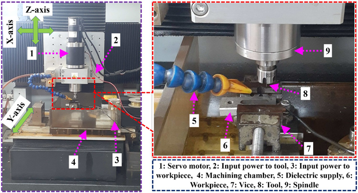
Preliminary experiments
Input parameters selected for single and multi-level texturing.
Surface generation through EDM machining
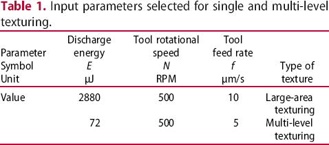
The EDM machined surface (EDMed) has unique characteristics primarily due to (a) the presence of a series of overlapped craters and (b) recast layer formation due to resolidification/redeposition of the molten metal. The EDMed is composed of a series of craters. The formation mechanism of a simple feature, namely a dimple, a pillar or a protrusion through the amalgamation of a series of craters, has been shown in Figure 2 (a), wherein C1-C4 depict four craters. These craters with certain overlapping result in generating a feature, say a dimple (D). Further, multi-level features are created by overlapping between the adjacent dimples to form a surface consisting of multiple features. Figure 2(b) shows a machined feature by combining two dimples (D1 and D2).
Schematic illustration of textured surface fabrication mechanism.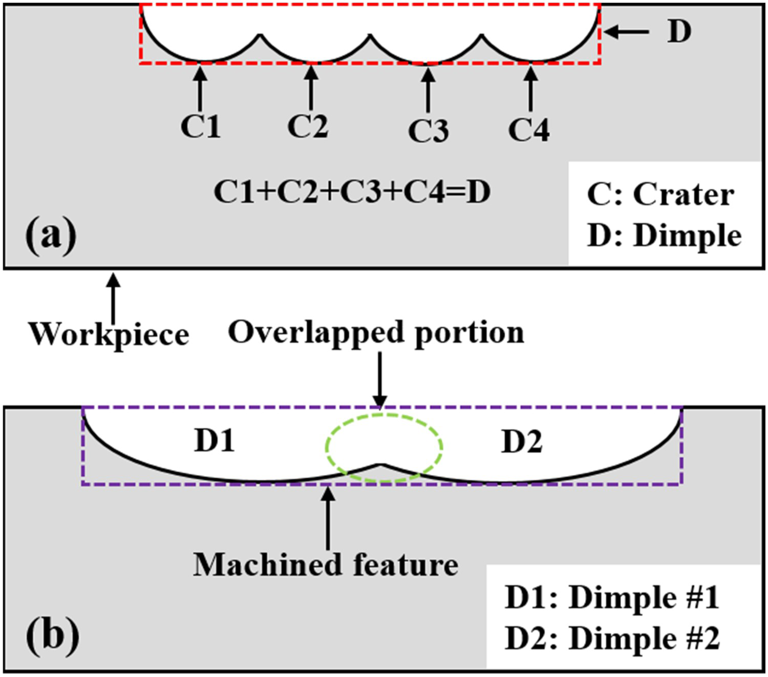
Results and discussion
Single-level textures fabrication using EDMM
Single-level textures refer to distinct micro-features, i.e. micro-dimples with the pitches between dimples greater than the diameter of a single dimple rather than simultaneous machining of more than one feature. Therefore, at a time, one kind of micro-feature is machined.
Micro-dimples array fabrication and wettability test
Micro-dimples array was fabricated on the Ti–6Al–4V sheet while maintaining a pitch between two dimples such that there is a separation between the dimples’ edges. A WC tool electrode of average diameter 148 μm (after dressing through block-electric discharge grinding, i.e. block-EDG process) has been employed (refer to Figure 3(a)) for micro-texturing at the discharge parameters and their values given in Table 1 (row 2).
(a) Micro-tool machined using Block-EDG process (average diameter ∼148 μm), (b) optical image of an array of micro-dimples machined on Ti–6Al–4V using the tool machined in (a), (c) SEM image of the selected features, and (d) water CA measurement on textured surface.
Optical microscopic (OM) image (Figure 3(b)) reveals the series of micro-dimples created on a Ti–6Al–4V surface with a constant depth of 50 μm, whereas the centre spacing between them in x- and y-axes is maintained at ∼350 μm. The average diameter of the machined dimples was measured to be ∼160 μm, and the variation in dimple diameter from the initial dimple (dimple No. 1) to the last dimple (dimple No. 99) was within 5%, which is well within an acceptable limit. Microstructural examination via. scanning electron microscopy (SEM) of a dimple's surface reveals the presence of overlapping craters, resolidified metal and debris, as shown in Figure 3(c). Contact angle measurement was done using the Goniometer (drop shape analyzer, Kruss Scientific, Germany) with water as the dropping phase (droplet volume 5 µl) in the air surrounding media. The contact angle (CA) measurement of the water droplet is shown in Figure 3(d), which offers a significant increment in water CA, i.e. ∼105.5°, compared to that of untextured surface, i.e. water CA ∼ 38°. The increase in water CA can be attributed to the entrapped air within the dimples, implying an upward tangential force on the water droplet. Moreover, the adhesion of the water droplet to the surface decreases due to a film of air being created at the interface of the water and the machined surface.
Figure 4(a,b) displays 3-D and line graphs of a few dimples, which confirm uniformity in dimples’ depth and a slight reduction in dimples’ diameter along with their depth ascribed to the side erosion of the micro-tool. Examining the 3-D topography of a single dimple suggests a bowl shape outline (Figure 4(c)), with a maximum diameter at the top and a slight reduction in the diameter with the depth, as depicted in the line graph (x- and y-directions) and of a single dimple shown in Figure 4(d).
(a) 3-D profilometer image of an array of micro-dimples, (b) line graph showing cross-sectional view of the dimples, (c) 3-D profilometer image of a single dimple depicting a bowl-shaped cavity, and (d) cross-sectional view of the dimple in the x-and y-direction.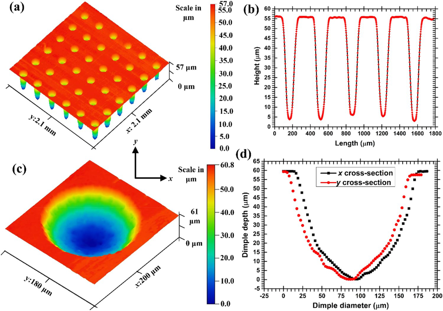
The linear machining rate (µm/s) depicts the rate at which a micro-feature, say a dimple or pillar, is machined. The average linear material removal rate at 72 µJ discharge energy, tool feed rate of 5 µm/s and tool rotational speed of 500 RPM was evaluated to be around 0.4 µm/s.
Wettability study of textured surface with varying dimples depth
Further, micro-dimples array fabrication on a relatively large Ti–6Al–4V surface (area ∼6 mm × 6 mm) was accomplished with a standard WC tool of diameter 500 μm and the high discharge energy, i.e. 2880 μJ, to reduce the overall machining time. Dimples’ depth was varied from the initial value of 25 μm to 50, 75 and 100 μm to analyse the influence of dimples’ depth on the variation in water CA. As depicted in Figure 5(a), a considerable increment in water contact angle was attainable (∼98° CA) on the textured surface of dimples depth of 25 μm from the untextured surface (∼38° CA). Moreover, there was a slight increase in water CA when the depth of dimples was further increased to 50, 75 and 100 μm (maximum CA of ∼110°). The increase in water CA can be accredited to the increased volume of trapped air within the dimples with an increase in the depth of dimples, implying a surface tension force on the water droplet, as represented in Figure 5(b). The surface tension force arising due to the entrapped air counterbalances the weight of the portion of the liquid droplet. Thus, a slight increment in water CA has been observed as dimples depth increases. However, the relative increase in water CA was not significant (∼10%) with greater dimple depth compared to 25 μm, as the additional trapped air volume may not further contribute to the water repellence phenomenon. Therefore, the optimum dimples’ depth in the given conditions varies from ∼75 to 100 μm.
(a) Variation of water CA on the textured surface with variable dimples depth (E: 2880 μJ, N: 500 RPM, f: 10 μm/s, dimples’ pitch in x-and y-axes: 750 μm), and (b) water contact angle measurement and entrapped air in the micro-dimples.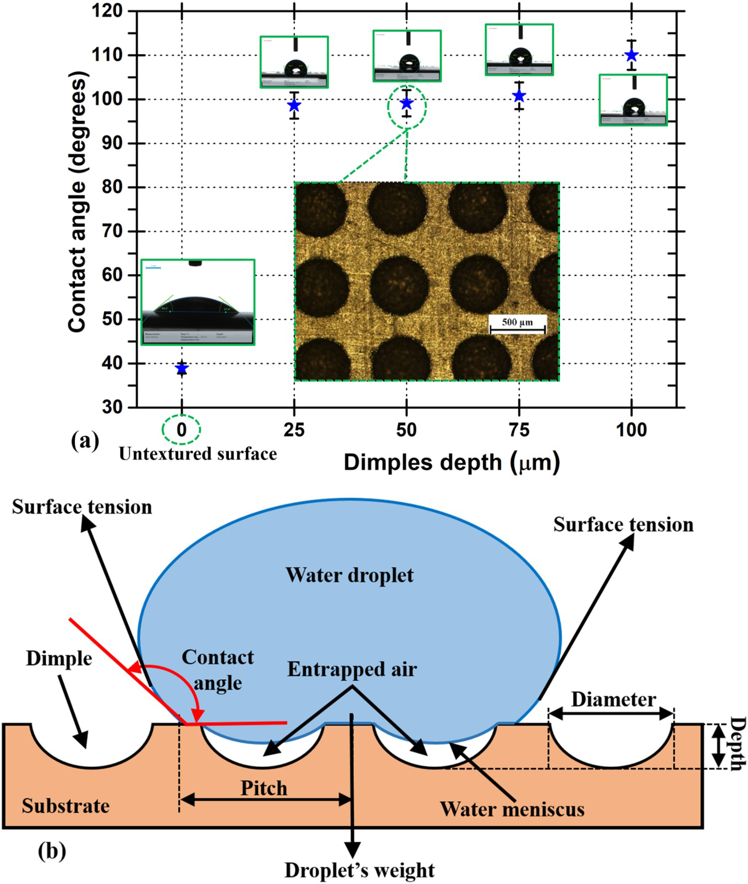
The linear machining rate (µm/s) is as high as 1 µm/s when a higher level of discharge energy (2880 µJ) was used with a tool feed rate of 10 µm/s, compared to that of around 0.4 µm/s at lower discharge energy of 72 µJ.
Multi-level textures fabrication through varying dimples overlapping
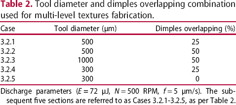
The EDMM process has been utilized for creating multi-level textures by varying the overlapping between the dimples. The multi-level surface generated by overlapping between dimples can induce differential surface roughness due to multiple micro-features (varying depths), contrary to single-level textures wherein the surface either consists of micro-dimples or micro-pillars separately. Optimizing the overlapping between adjacent dimples makes it possible to generate a surface comprising micro-pillars surrounded by micro-dimples. Dimples overlapping were calculated from the approximate average diameter of a dimple at a given set of input process variables (through preliminary experiments). The combination of dimples overlapping for a specific tool diameter (Table 2) has been selected to create multi-level micro-textured surfaces. The lower the overlapping between the dimples, the higher is the size of the micro-pillars for a given diameter of the tool electrode. However, increasing the overlapping dimples results in smaller pillar dimensions and higher numbers of dimples for the specific area of the substrate, i.e. higher machining time. Therefore, there is always a trade-off between the size of the resultant pillars and the productivity of the process. Figure 6(a,b) illustrates the machining of multiple micro-features through the variation in dimples overlapping, i.e. zero overlapping and a finite overlapping between the dimples. Ti–6Al–4V has been used as a workpiece substrate having a water contact angle of ∼38° for the untextured sample. However, there is a significant increase in water CA when multi-level textures are machined on the surface. The discharge parameters used for each combination were E Schematic illustration of multiple micro-features machining through dimples overlapping (a) for zero overlapping, i.e. dimples circumference touching, and (b) for a finite overlapping between the dimples. Tool diameter and dimples overlapping combination used for multi-level textures fabrication. Discharge parameters (E 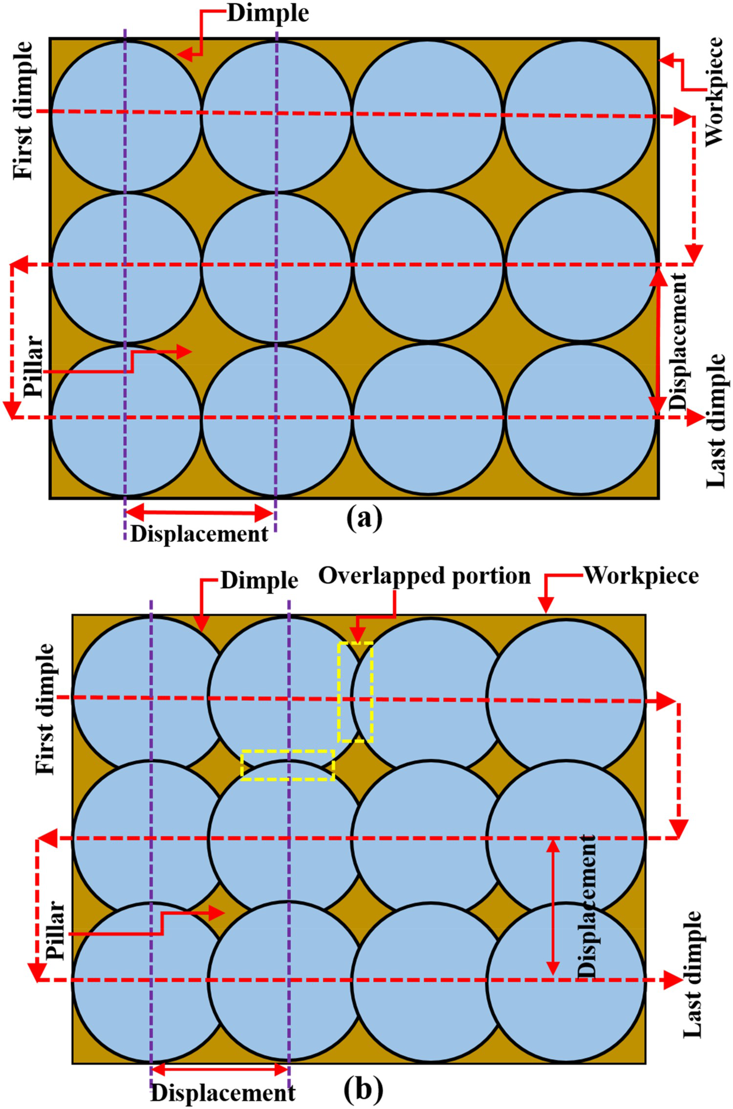
With 500 µm diameter tool electrode and 25% dimples overlapping
WC tool of diameter 500 µm and 25% overlapping between adjacent dimples was employed to create multiple features on the Ti–6Al–4V workpiece. Figure 7(a–d) present the optical picture, 3-D view, SEM image and a line profile, respectively, of the resultant multi-level textures, comprising of micro-dimples array surrounded by diamond shape micro-pillars. The diamond shape micro-pillars resulted from the unmachined portion of the workpiece between the four adjacent dimples. As the four dimples (two from each row) overlap, a small portion remains unmachined at the intersection of all the dimples. This unmachined portion adopts a diamond pillar's shape having a height approximately equal to an individual dimple's depth (∼20 µm). The diamond-shaped pillars’ average dimensions are ∼110 × 110 × 20 µm3 (refer to Figure 7(a,b)). Due to overlapping between two dimples, it has been observed that the peripheral region of the previously machined dimple was further eroded due to sparking during the machining of the overlapping zone. Thus, the shape of the dimples is visualized as hemispherical with an elevated portion near the centre (convex dimple), as shown in Figure 7(b). Water contact measurement in Figure 7(e) reveals the surface to be relatively hydrophobic, i.e. CA ∼98.6° as compared to ∼38° for an untextured Ti–6Al–4V surface. The trapped air between the micro-features prevents water penetration to the bottom of the surface, which eventually increases the water CA, as discussed in Section ‘Wettability study of textured surface with varying dimples depth’.
Multiple micro-features machined using dimples overlapping (a) optical microscope image, (b) 3-D view, (c) SEM image, (d) line graph of the multi-features, and (e) water droplet CA measurement. (Tool diameter: 500 µm, dimples overlapping: 25%, i.e. dimples pitch: 435 μm in x- and y directions, dimples depth: 20 µm).
The global profile variation (waviness) of the multi-level machined features and surface roughness (local or closely spaced irregularities) is visualized in Figure 8(a). The average surface roughness value (Ra) of the multi-level textured surface is measured as 2.1 µm compared to that of an untextured surface (0.10 µm), inducing definite surface roughness to the machined surface. As revealed in Figure 8(b), the SEM image of the dimple's surface shows the existence of resolidified molten metal (which forms a recast layer), a few micro-cracks originating on the surfaces and dispersed debris. Effective evacuation of resolidified molten metal and debris particles is indispensable for the improved machining efficiency of the EDM process.
(a) Surface roughness and profile measurement of the multi-level textured surface, and (b) SEM micrograph of the machined dimple's surface.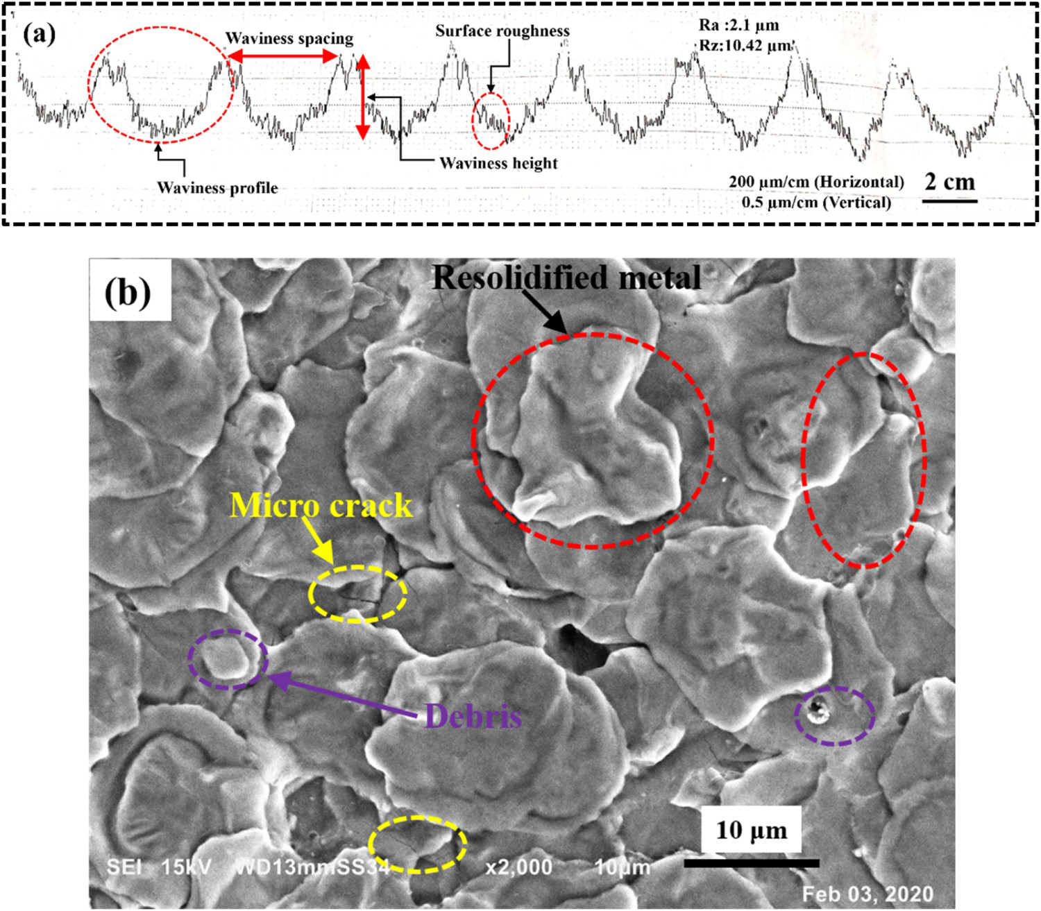
With 500 µm diameter tool electrode and 50% dimples overlapping
Using a WC tool with a diameter of ∼500 µm and 50% dimples overlapping between neighbouring dimples, a relatively smoother surface with minor pillars of height less than ∼10 μm between the convex dimples was achieved. Figure 9(a) reveals a nearly smooth surface with dimples boundaries slightly visible through the OM image. The edge between two dimples were eroded as the subsequent dimples were intended to machine such that the newly machined dimples’ circumference coincides with the centre of the previously machined dimple. However, the machined surface characteristics may differ near the dimple's boundaries due to the coinciding dimples. Similar to the previous case (Section ‘With 500 µm diameter tool electrode and 25 % dimples overlapping’), the dimples exhibit a convex shape, i.e. micro-protrusions, with a height of ∼20 μm. Minor pillars of significantly smaller dimensions between convex dimples were observed in the 3-D image, as shown in Figure 9(b–c), illustrating the uniqueness of the process of creating multiple micro-features. Although the water contact measurement (Figure 9(d)) shows a slight increase in CA from the plain Ti–6Al–4V surface, the surface is still hydrophilic, probably due to the smaller height of pillars and relatively smoother surface.
Multiple micro-features machined using dimples overlapping (a) optical microscope image, (b) 3-D view, (c) line profile of the multi-level textures, and (d) water droplet CA measurement. (Tool diameter: 500 µm, dimples overlapping: 50%, i.e. dimples pitch: 290 μm in x-and y- directions, dimples depth: 20 µm).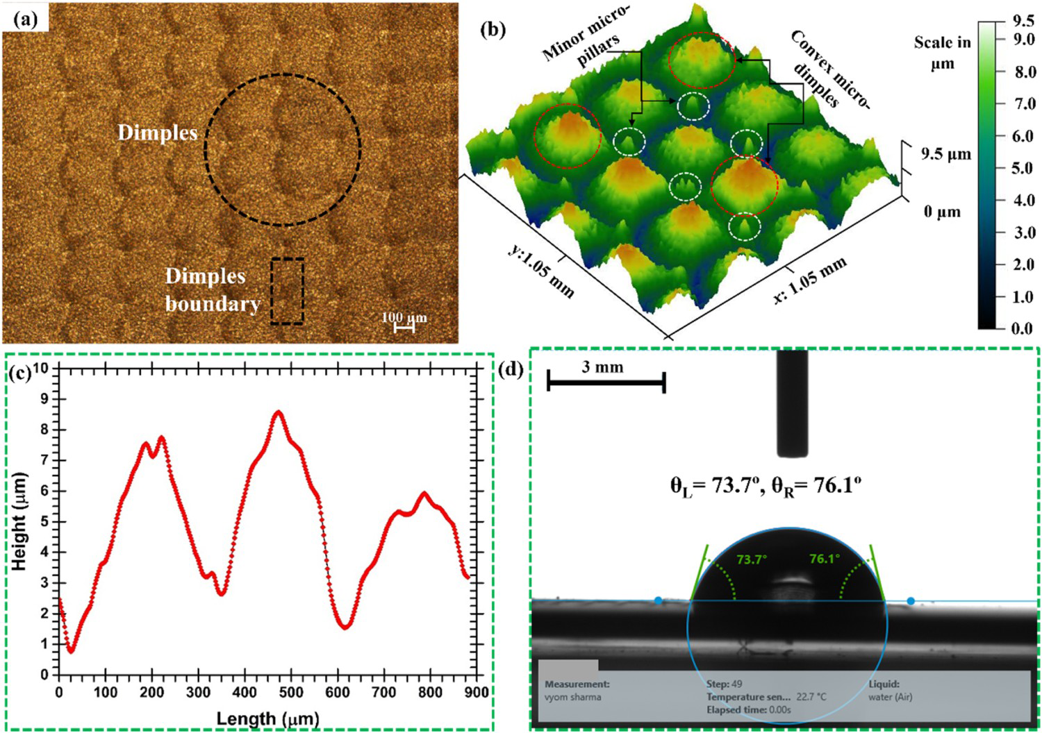
With 1000 µm diameter tool electrode and 50% dimples overlapping
Further, employing a WC tool of mean diameter ∼1000 µm and adopting dimples overlapping 50% of the dimple's diameter, three levels of the features were created, as shown in the OM image, profilometer image and line graph (refer to Figure 10(a–c)). The topography features consist of near square-shaped pillars with maximum height, hexagonal shape pillars of relatively lower height and the depressed bottom portion due to the machining of adjacent dimples. The 3-D image, as shown in Figure 10(b), indicates the multi-level micro-features. Owing to the overlapping between the dimples, the adjacent dimples resulted in machining the previously machined feature. Water contact measurement in Figure 10(d) reveals the hydrophobic nature of the surface (CA∼95.8°) with respect to the untextured Ti–6Al–4V surface (CA ∼38°).
Multiple micro-features machined using dimples overlapping (a) optical microscopic image, (b) 3-D view, (c) line profile of the multi-level textures, and (d) water droplet CA measurement. (Tool diameter: 1000 µm, dimples overlapping: 50%, i.e. dimples pitch: 540 μm in x-and y- directions, dimples depth: 20 µm).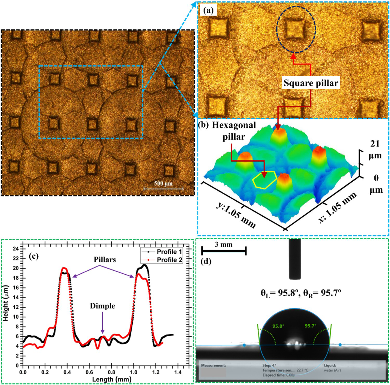
With 300 µm diameter tool electrode and 25% dimples overlapping
The diamond-shaped micro-pillars of sizes ∼100 × 100 × 50 µm3 and micro-dimples in between the pillars were machined, as shown in Figure 11(a), with the help of a 300 µm diameter tool and 25% dimples overlapping. The machined features from the optical profilometer and line images (Figure 11(b,c)) show a unique pattern wherein slightly higher depth micro-pillars surround a series of micro-dimples. Thus, it represents a surface of multiple features with varying depths. A line graph of the machined feature (Figure 11(c)) at a selected region confirms the presence of micro-dimples and micro-pillars simultaneously. Concave-shaped micro-dimples can be observed (Figure 11(b)), and the engineered surface offers two levels of patterns containing shallower dimples between the adjacent pillars. A higher water contact angle of ∼104.2° was obtained in Figure 11(d) caused by relatively larger features’ depth (∼50 μm).
Multiple micro-features machined using dimples overlapping (a) optical microscope image, (b) 3-D view, (c) line profile of the multi-level textures showing pillars (rectangular peaks) and dimples (valleys between the pillars), and (d) water droplet CA measurement. (Tool diameter: 300 µm, dimples overlapping: 25%, i.e. dimples pitch: 275 μm in x-and y- directions, dimples depth: 50 µm).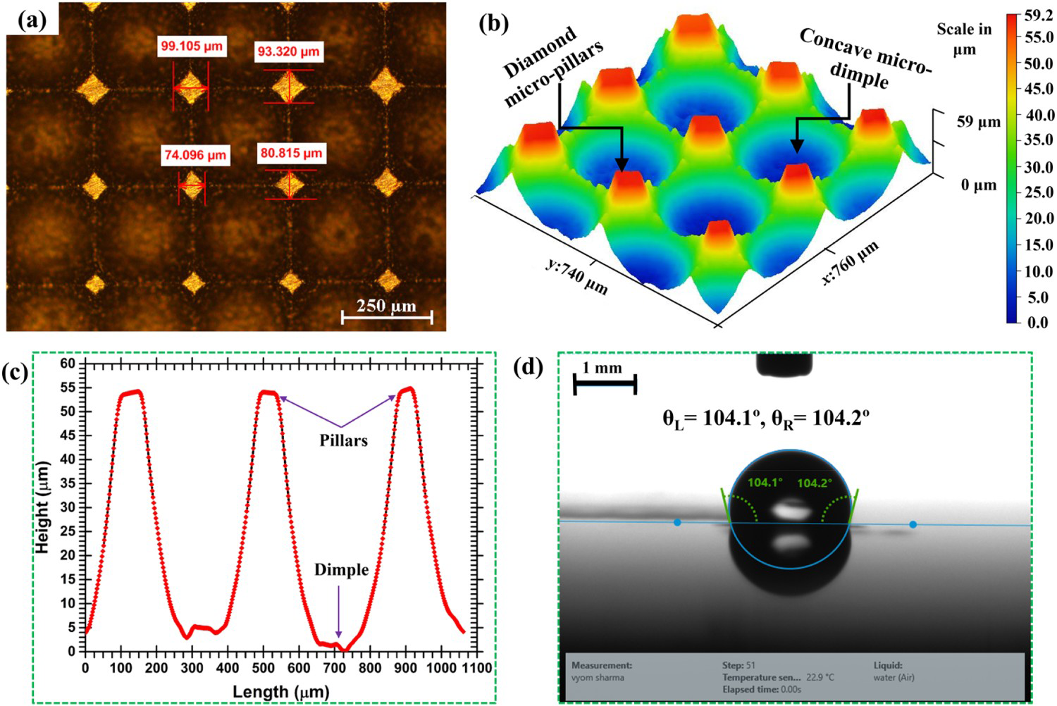
With 300 µm diameter tool electrode and no dimples overlapping
No dimples overlapping refers to a case wherein dimples’ boundaries nearly touch one another. It is essentially different from the array of micro-dimples discussed in Sections ‘Micro-dimples array fabrication and wettability test’ and ‘Wettability study of textured surface with varying dimples depth’, where there is a definite spacing between the boundaries of dimples. Diamond-shaped micro-pillars of average sizes ∼212 × 212 × 50 µm3 were achieved with zero dimples overlapping by employing a tool of ∼300 μm diameter. Figure 12(a–c) depicts the optical image, 3-D view and line profile, respectively, of the fabricated surface consisting of micro-dimples and micro-pillars. Figure 12(d) reveals the water contact angle measurement (water CA of ∼91.7°) on the textured surface with hydrophobic nature.
Multiple micro-features machined using dimples overlapping (a) optical microscope image, (b) 3-D view, (c) line profile of the multi-level textures showing pillars (rectangular peaks) and dimples (valleys between the pillars), (d) water droplet CA measurement. (Tool diameter: 300 µm, dimples overlapping: 0%, i.e. dimples pitch: 300 μm in x- and y- directions, dimples depth: 50 µm).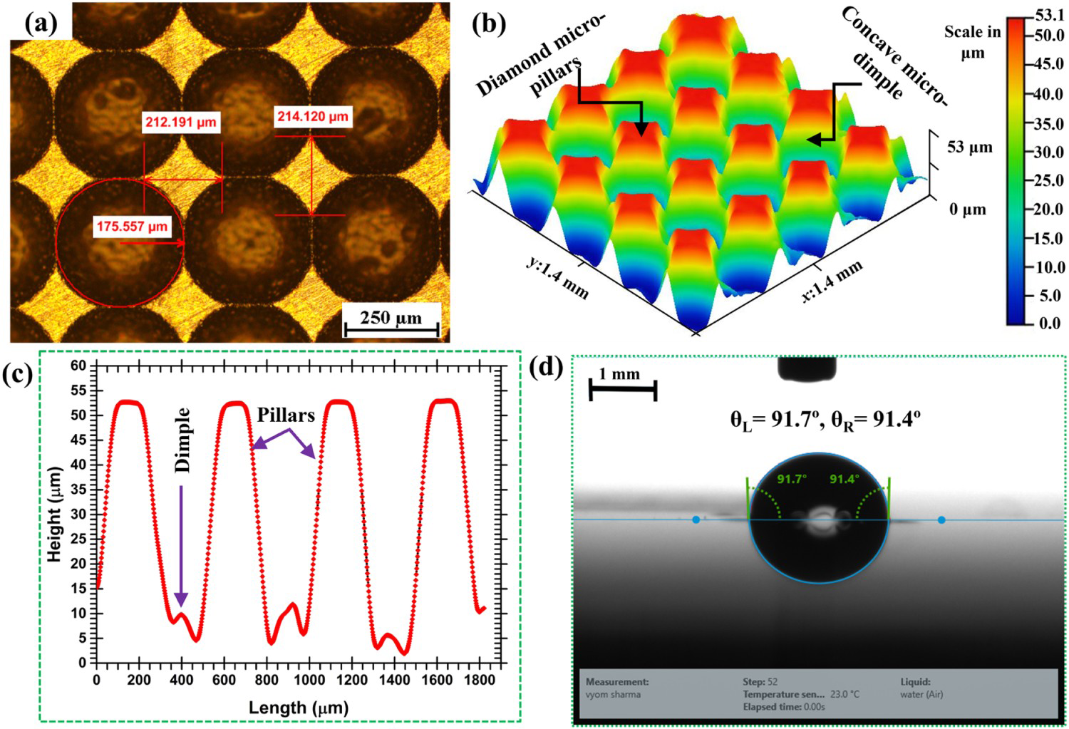
Water contact angle on the multi-level textured surfaces
The bar graph (Figure 13) compares water CA obtained with different multi-level textured surfaces corresponding to Table 2. Except for case 3.2.2, other textured surfaces behave as hydrophobic surfaces (water CA > 90°) as opposed to the smooth surface (water CA of ∼38 °). The phenomenon of air entrapment in the micro-sized cavities and the resultant force of surface tension on water droplet explain the increase in water CA, as explained earlier in Section ‘Wettability study of textured surface with varying dimples depth’. The size of micro-pillars, i.e. cross-sectional area, depth, and pitch between the pillars, predominantly influences the water contact angle, i.e. the hydrophobicity of the textured surface. Area density (ratio of the cross-sectional area of the pillars to the total substrate area) is an important factor, which determines the water contact angle. Area density is influenced by the size of the pillars. The relatively higher surface energy of Ti–6Al–4V facilitates water spreading on the surface, resulting in lower water CA on the smooth surface.
Measured water CA on the different multi-level textured surfaces compared to the untextured surface. (Cases 3.2.1–3.2.5 in the abscissa show different cases as per Table 2).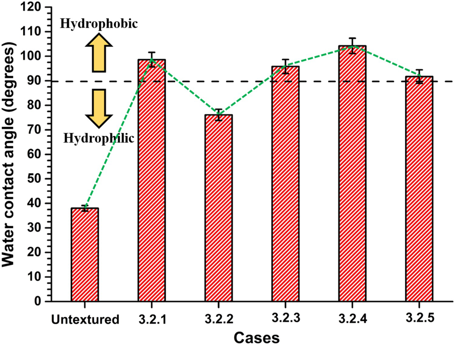
Conclusions
The current study focused on machining the array of micro-dimples (single-level textures) on large surface areas and generating multi-level textured surfaces with multiple features through dimples’ overlapping using the EDMM process. The following conclusions are derived from the study:
A block-EDG machined tool has successfully demonstrated for array of micro-dimples machining on Ti–6Al–4V with uniform diameter and depth of the features. The machined surface was hydrophobic (water CA∼105.4°) compared to the smooth hydrophilic surface (CA∼38°). A significant improvement in water repellence behaviour (increased water CA from 38° to ∼ 100°) of the Ti–6Al–4V sheet with a micro-dimples array of dimples depth 25 μm was observed when textures were machined on larger surface using a tool of 500 µm diameter. An increase of ∼189% in water CA was achieved for dimples depth of 100 µm than the untextured Ti–6Al–4V surface, depicting the hydrophobic behaviour (water CA ∼110°). Multiple micro-features were created simultaneously with varying dimples overlapping. Diamond-shaped micro-pillars were successfully machined surrounding the convex/concave micro-dimples, which are otherwise difficult to generate via. single-step fabrication. Except for a single case, all multi-level textures reported in the manuscript have depicted hydrophobic behaviour offering the proposed technique for multi-level engineered surface creation.
Overall, the single and multi-level textured Ti–6Al–4V surfaces exhibited hydrophobicity compared to the untextured surface. Though the proposed concept of multi-level textures was executed on a smaller surface area and smaller features’ depth, future prospects would include the implementation of the proposed methodology to manufacture textures on a large-area for bio-tribological, corrosion resistance, solar cells, biosensors and heat transfer applications.
Footnotes
Disclosure statement
No potential conflict of interest was reported by the author(s).