
Abstract
The material deposition in aqueous solution, also known as chemical bath deposition (CBD), is a well-established technique for the fabrication of semiconducting thin films. The success of the CBD technique is mainly based on the relatively easy implementation and operation requirements. The CBD has importantly contributed to the development of sensors, optical devices and solar cells applications. In this review, the origins and current state of the art of the CBD technique, the involved physicochemical processes, the growing mechanisms, and the analytical techniques for the estimation of optimal physicochemical conditions for the film deposition are discussed. Emphasis on authors’ experience on CBD of CdS, ZnS, Zn(OH)2, and ZnO films are here highlighted, following methodologies for a high control of the deposited materials, such as the species distribution diagrams and the solubility curves.
The chemical bath deposition technique
Origins, generalities and importance
Chemical bath deposition (CBD) technique is a widely used methodology for the growth of materials in thin film geometry with thicknesses ranging from few nm to several microns. This growing method is one of the simplest, cheapest, and easiest to control and implement. The process can be envisioned as a technique where the product is generated and deposited in the same place (the chemical bath). The prepared materials are very comparable with other synthesis pathways using more complex/expensive techniques in terms of quality, physical properties, and adequate conditions for further applications, especially for the commercial interests. Such a technique has been used for many years, for different aims and for a variety of compounds. Great efforts to elucidate the influence of each of the involved parameters have been developed and spread among the scientific community, from the variation of experimental conditions to theoretical approaches based on physicochemical foundations and experimental observations. This review aims to bring a general overview of the CBD technique, the historic evolution and key findings throughout the years, the effect and influence of the major-importance parameters on the resulting materials and the well-established rules of this specific technique. Authors’ perspectives and critical analysis are highlighted, with the aim of bringing clarity on the next steps, missing areas and gaps on the current knowledge.
According to Hodes [1], the very first report citing the usage of the CBD technique was in 1869 by Puscher. Some years later, at the beginning of the twentieth century, the rising of the photoconductivity phenomenon promoted the use of the CBD technique for the deposition of PbS films as reported by Rosenheim et al. [2,3]. Other pioneer groups on the usage of CBD according to Ezekoye et al. [4], are the groups of Bode [5], Hass [6] and Chopra [7]. However, it is considered that a main boost for the spreading and renaissance of the CBD technique took place with the rising of the photovoltaic cells based on thin-film geometry, particularly the CdS/CdTe solar cells [8-11].
The CBD process is carried out using an aqueous solution at a low temperature (usually below 100°C) and atmospheric pressure, using distilled/deionized water as host medium. The control of the main parameters during the chemical bath process is relatively easy and systematic. The most common reported materials are metal chalcogenides (sulphides and selenides) followed by tellurides [1,12]. Chalcogenides deposition by CBD consists in the slow precipitation of the basic material when the metal ions and chalcogenide ions react in alkaline aqueous solutions [13]. Metal selenides deposited by CBD such as CdSe [14], ZnSe [15] PbSe [16], CdZnSe [17] and CdSSe [18] can be cited. Another important group of deposited materials by CBD are the oxides, where the main mechanisms reported are the hydrolysis of metallic salts with boric acid/fluorocomplexes [1]. Other relevant semiconducting material is Ge [19,20]. However, a main drawback for Ge is the strong covalent character of the Ge–Ge bond [19], which requires temperatures above 200°C, being this beyond the CBD temperature range.
The basic experimental setup of the CBD technique consists in an aqueous solution in a glass container, heated by a hot plate, see Figure 1. The solution is usually stirred for homogenization purposes. The temperature and pH of the solution are measured and controlled during the process. The substrates introduced to the chemical bath must remain chemically stable to avoid chemical modification of the solution. The substrates can be placed at different positions within the chemical bath [21].
Experimental setup for the CBD technique.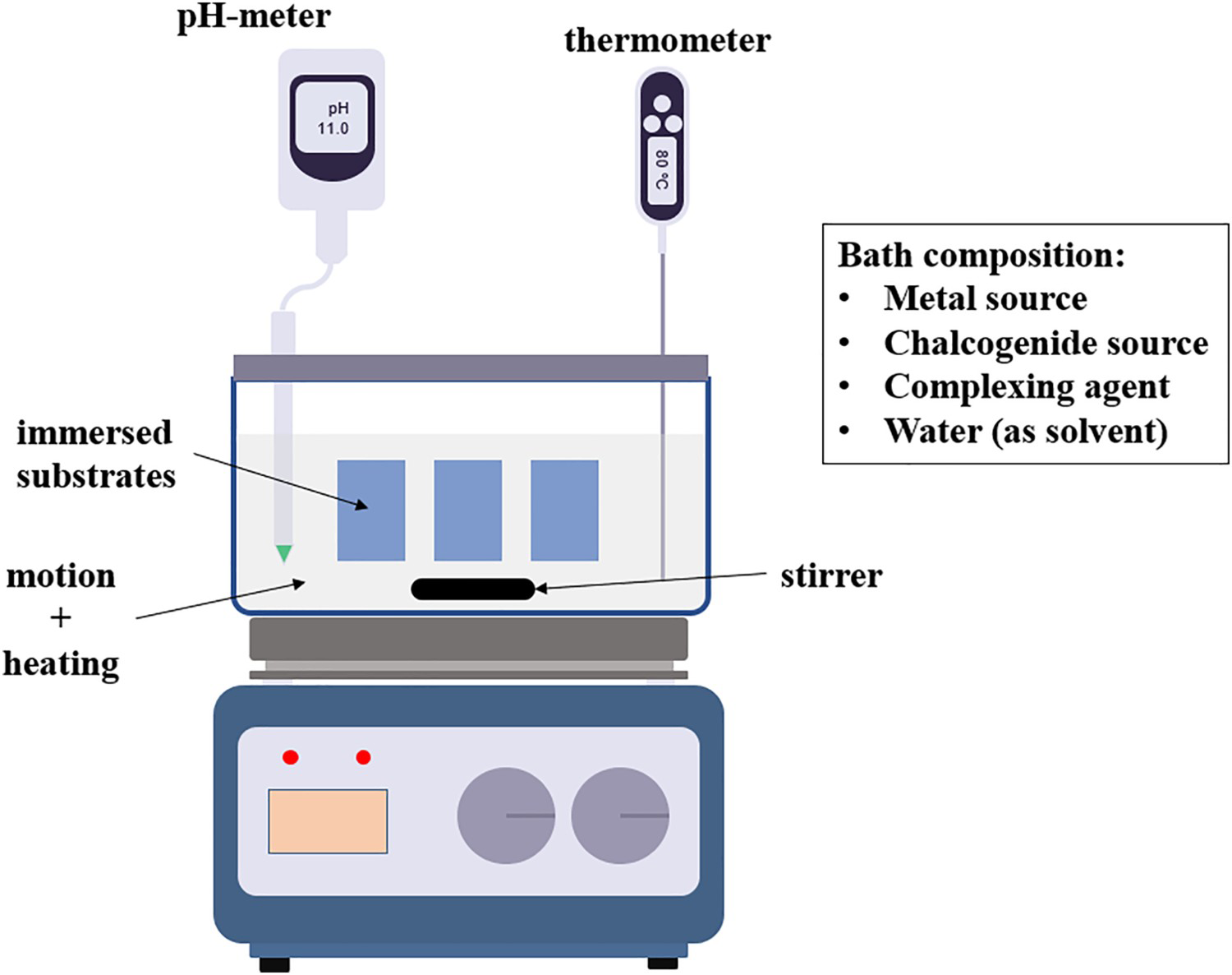
One of the main environmental concerns for the CBD technique is the use of ammonia as complexing agent due to the high volatility and toxicity [22]. However, the use of ammonia can be avoided by changing it to less harmful compounds such as citric acid [23], tri-sodium citrate [24] or even removing it from the growth solution [25]. Efforts have been recently made to adapt the CBD methodology for better considering the sustainability of the process [26,27].
Chemical process: an overview
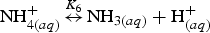
General steps involved in the sequence of the CBD technique are already recognized and can be found elsewhere [1,4,28-30]. As a first step, the creation of species occurs mainly promoted by the so-called ion-by-ion or cluster-by-cluster mechanism, where material quantity increases. Such processes occur at the nucleation sites which generally depend on the type, quality and conditions of the substrate [1,28,29,31]. Such species travel in a medium and then condensate at the substrate. A key concept here is the solubility product (Ksp
), a value which must be exceeded by the ionic product to initiate the formation of the species; otherwise, the solid phase will be dissolved back [4,12,32,33]. Ksp
mainly depends on bath temperature, type of solvent, and particle size [32]. The material is then deposited onto substrates immersed in the bath. The film thickness is correlated with parameters such as the pH, the deposition rate and the bath temperature [4,28]. Figure 2 illustrates the main processes involved in the CBD technique.
Chemical bath deposition main processes.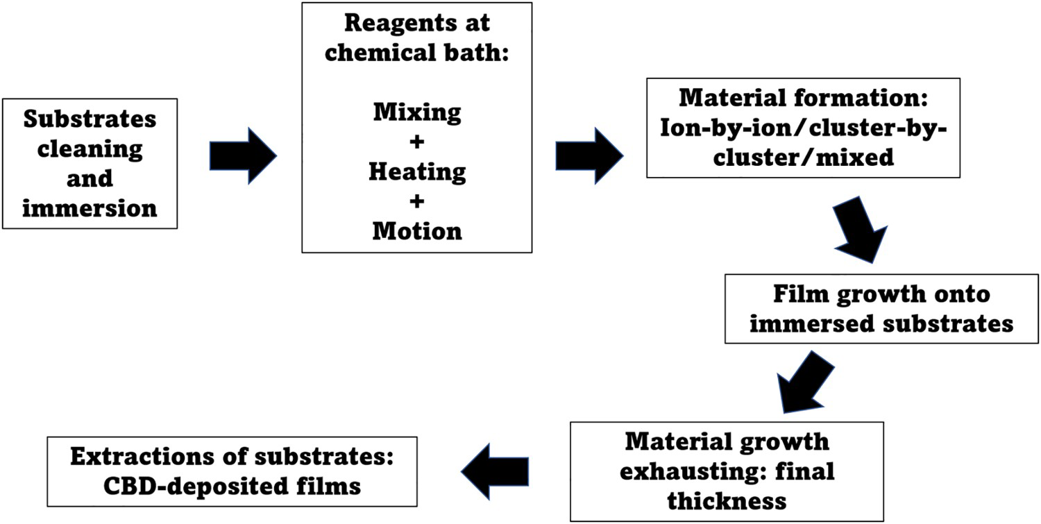
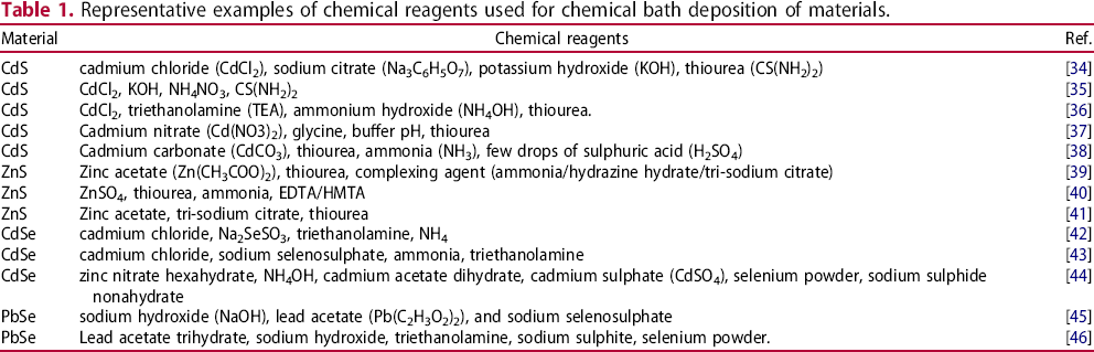
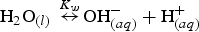
Representative examples of chemical reagents used for chemical bath deposition of materials.
Role of substrate: cleaning, type, and orientation
Owing to the versatility of the CBD technique, a wide variety of substrates can be used. The glass substrate has been the most used due to the transparency (for optical applications), but the use of flexible polymeric substrates has also been reported. Polymeric substrates have become popular and of technological relevance due to the potential applications in flexible electronics and photovoltaic devices [47,48]. Some studies on polymer nanocomposite substrates for deposition of semiconducting CBD thin films have been reported, envisioning future applications in photovoltaic devices; novel conducting polymers may help on the back contacts requirements [47]. As a very first step, substrates undergo a formal cleaning process, usually consisting in cleaning with detergent, rinsing water and different types of solutions such as trichloromethylene, isopropyl alcohol, acetone, trichloroethylene. Ultrasonic bath is usually used for cleaning the substrates immersed within the mentioned solvents. The cleaning process prepares the surface to correctly form nucleation sites for the material, improving the adhesion conditions for the thin films. Some reports have proposed the coating of the substrate prior the deposition of films by CBD; the presence of a monolayer can be used to generate specific patterning as can be found at [1]. The orientation of the substrates within the chemical reaction at CBD has been also explored [49]. The crystallographic conditions strongly depend on the nature of the substrate, which can be understood from the ion-by-ion and/or cluster-by-cluster growth process inherent to the CBD technique. However, it is important to mention that, as Froment and Lincot stated [50], the lateral homogeneity of CBD films is good, even on irregular surfaces, since the growth is often under kinetic control. Such a characteristic represents a great advantage for the CBD, not shared by other deposition techniques.
Alternative CBD conditions
Although the CBD process and equipment are generally well-known, alternative conditions, stimuli, or additional devices adapted to the technique have been reported. Such modifications intend to improve and/or better control specific parameters and reactions to promote enhanced conditions for the resulting thin films. Different strategies such as microwaves [51-64], hydrothermal [65,66], light [67,68], seed-layer [69,70], ultrasonic wave [71], and surfactants [72] have been reported as additional/alternative conditions for the CBD. Some advantages that such strategies have offered are time reduction [51,54,60], energy saving [64,67] and enhanced physical properties for the further applications [66,69,72].
Applications related to CBD-grown materials and comparison with other techniques
A very relevant field where most of the semiconductors obtained by CBD are implemented is the photovoltaic energy field. For example, a very reported application for CdS thin films is the use as a window layer in the CdS/CdTe solar cell structure [73-75]. Jun Wang et al. [73] reported a comparative study where different techniques were used for the CdS fabrication: magnetron sputtering, homogeneous precipitation and CBD. The effect of change of reactants in the chemical bath and the use of thermal annealing have been also explored in terms of the CdS/CdTe solar efficiency [74,75]. Magorian Friedlmeier et al. [76] carried out a comparative study between CBD-deposited CdS and ZnS as window layers in the CIGS cell; the solar cell efficiency was higher than the reported using different deposition methods, such as sputtering and atomic layer deposition [77,78]. Another absorbent material grown by CBD is SnS [79], with the main advantage of modifying its structure from cubic to orthorhombic [80]. Also, by the modification in the stoichiometry of the SnxS1-x compound during the CBD, the bandgap energy can be tailored improving the absorption efficiency of the material [81].
The chemical bath deposition, processes in equilibrium
The CBD chemical reactions
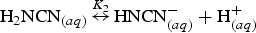
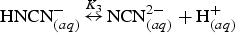
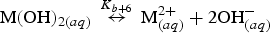
The first group of chemical reactions to be considered in the CBD technique is the hydrolysis of all the reactants with the solvent, commonly water. The cation source comes exclusively from a soluble binary salt whose anion is almost inert in solution. This anion should be a weak base to avoid a precipitation competition with the chalcogenide anion, such as Cl– [82, 83], SO4 2– [82-84], CH3COO– [82-84] or NO3 – [82,83]. Although the anion participates in the collateral chemical reactions, due to its relatively low concentration (≈1 mM) its influence is often neglected. Nevertheless, its presence affects the overall activity within the solution which impacts the morphological properties of the thin films. For example, Cl– and SO4 2– increase film density and promote smoother surfaces [82,83]. On the other hand, in the hydrolysis of metallic cations they will react with the hydroxide ions of water. According to their coordination sphere, it involves from 4 to 6 complexing reactions. Also, the anion source, which is typically thiourea, involves around 5 chemical reactions. The hydrolysis of the thiourea, for example, converts the cations into sulfidric acid and cyanamide. The other 6 reactions are the hydrolysis of these subproducts. Finally, the hydrolysis of the complexing agent source should originate an anion able to coordinate the metallic cation. If a counter-ion is also generated, it should play as an ion spectator with no role in the reaction system.
The second group of chemical reactions is the complexation reaction of the metal ion with the complexing agent. Depending on the coordination sphere of the cation, it could participate from 4 to 6 complexing reactions. A third group of chemical reactions that takes place is responsible for the deposition of the chalcogenide material. If the reactants and bath conditions are well selected, only the sulphide and hydroxide precipitations should occur in solution, which adds two additional reactions. Thus, in a simplified system, reactions of hydrolysis, complexation and deposition of chalcogenide render from 17 to 19 chemical reactions can simultaneously occur in the solution at the CBD technique.
Hydrolysis and complexation
The complexation process involves the formation of the coordinate covalent bond between a positively charged species M, typically a transition cation, and an anion or molecule with free electron pairs known as ligand L, see Equation (1),

In the CBD of chalcogenides, M is commonly Cd2+, Zn2+, or Hg2+. For these cations, theoretical studies point that their coordination numbers normally range from 4 to 6 (Zn2+) and from 6 to 7 (Cd2+, Hg2+) [85,86]. Besides, complexation is an important process of the CBD technique because it enhances the deposition control and avoids the excessive formation of precipitates. As many of these reactions are carried on aqueous solutions, water can react with M in a process called hydrolysis as follows,

The solubility product
The precipitation begins when the amount of M overcomes the capacity of water to retain it in solution, or when M forms a more stable compound with other species, according to Equation (4),

The chemical reactions
The main chemical reactions considered for the CBD of metallic sulphide (MS) for divalent cations are,
Thiourea dissociation,
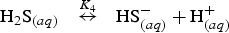
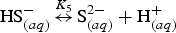
Dissociation of hydrogen sulphide,
Decomposition reaction of ammonium to ammonia,
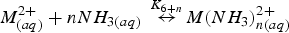
Divalent metal complexation with ammonia ligands,
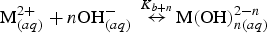
Divalent metal complexation with hydroxyl ligands,
Solid phase formation of MS,
Water dissociation,
If M = Zn, n = 1–4; if M = Cd, n = 1–6.

n = 1–4, both for M = Zn and Cd.
The b counter in Equations (12)–(14) depends on the identity of the metal (if M = Zn, b = 10; if M = Cd, b = 12). This counter contemplates the sequential position (namely numbering) of the remainder reactions considering the last complexation reaction of zinc or cadmium with ammonia ligands. If M = Zn, the last complexation reaction with ammonia ligands permits the formation of Zn(NH3)4
2+ species, Equation (11); then, the following zinc complexation reactions with hydroxyl ligands are expressed at Equations (A.11)–(A.14) (see section A in Supplementary Information). If M = Cd, the complexation reaction with ammonia ligands allows the formation of Cd(NH3)6
2+, Equation (12), and in consequence, the complexation reactions for cadmium with hydroxyl ligands are numbered from (B.13) to (B.16) in the section B of the Supplementary Information.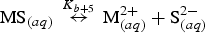
The last group of chemical equations will depend on the complexing agent. For the reactants used for Zn or Cd films deposition developed by our group, the complexing agent was NH4NO3. Thus, Equations (10) and (11) are necessary for the other ammonium-based complexing agents, such as NH3 or NH3OH.
For ZnS, the reaction constants Ki
in Equations (5) to (15) depend on the absolute temperature T. These parameters can be readily calculated at any temperature from Equation (16) [87],

Importance of the selected chemical reagents
Reagents and substrates used for depositing different materials through the CBD technique.
An adequate selection of chemical reagents prevents contamination of the precipitate, which directly affects the solubility. Kokotov et al. [112] observed that the presence of contaminants (Fe2+, Fe3+, Mn2+) in the ethanolamine complexing agent solution improves the ZnO deposition. Authors attributed this effect to the formation of hydrated oxides (FeOOH and MnOOH) which adsorb heavy metals ions and act as nucleation centres for ZnO growing.
Kinetics of growth
Film thickness
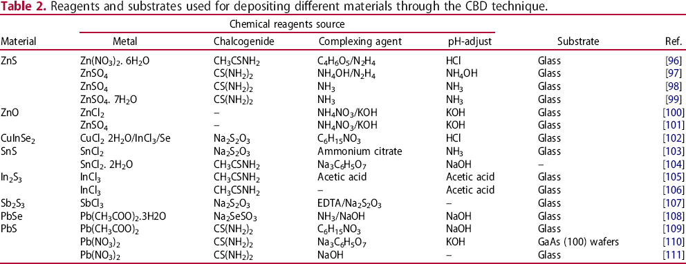
The most used methodology for analysing the growing behaviour of the nanomaterial in the precursor solution is measuring the film thickness as a function of deposition time. The value of thickness can be measured in situ or post-deposition of the material by means of SEM images or a profilometer [113,114]. Regardless of the type of compound to be synthesized, the film thickness as a function of growing time follows a general behaviour which is composed by three zones: induction, growth, and saturation [115, 116]. In the induction zone, the nucleation process of the material occurs. During this time, the chemical reactions begin in the precursor solution, resulting in the formation of the first nuclei of the material (Figure 3(a)). Subsequently, these nuclei initiate a diffusion process through the solution until it reaches the surface of the substrate (Figure 3(b)). The substrate adsorbs the particles, which acquire larger size through aggregation or coalescence (Figure 3(c)), starting the growth zone. The increase in thickness of the material presents a linear behaviour with time. The number of nuclei depends on the concentration of the precursors, therefore, after a certain time, the source of ions reduces and the solution cannot create more nuclei, which inevitably leads to a slowdown or stoppage of the growth of the nanomaterial (Figure 3(d)).
Scheme of the stages of growth of nanomaterials by CBD as a function of time. (a) Nuclei formation, (b) nuclei diffusion towards the substrate surface, (c) nuclei agglomeration and thin film growth initiation, (d) saturation of the deposition solution and end of growth.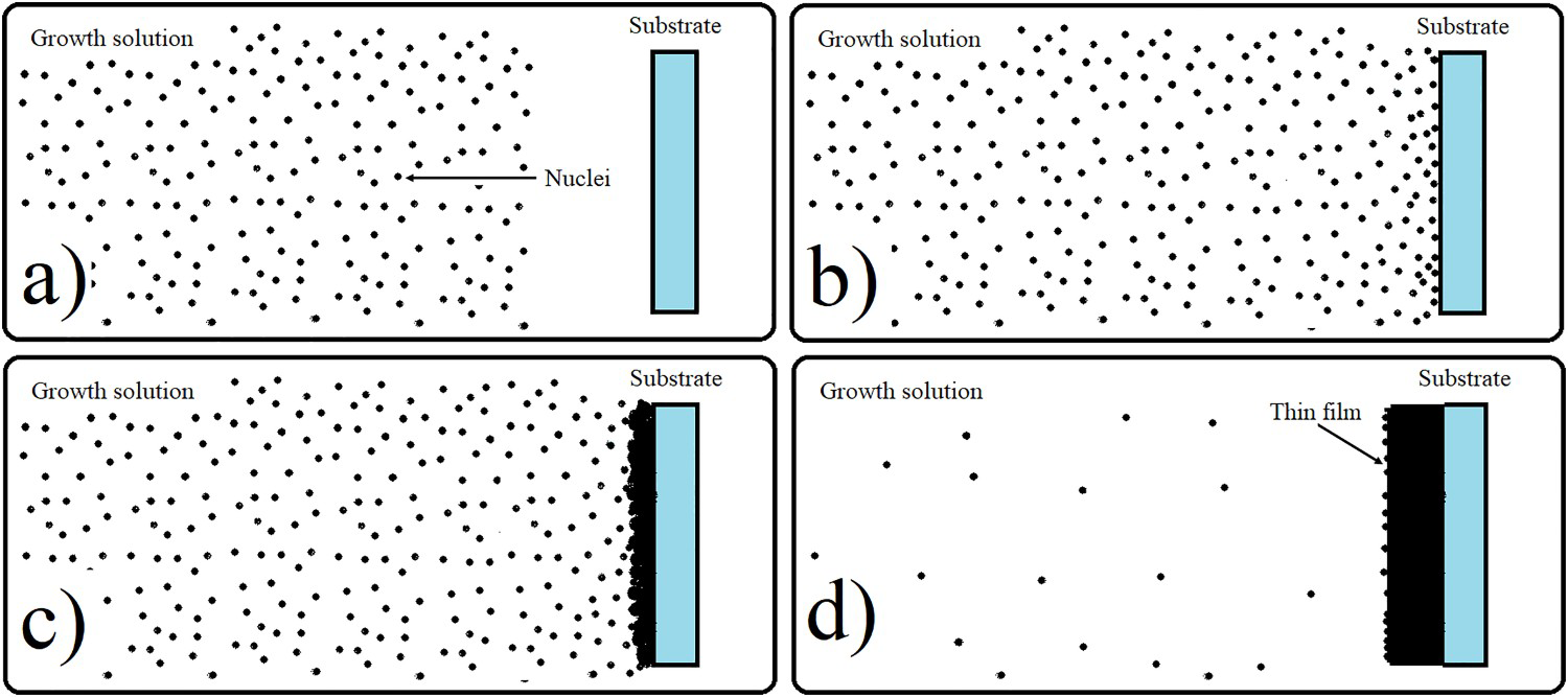
In the saturation zone, the deposition time is over because no more free ions are in solution. At this time, the deposited film requires to be withdrawn from the aqueous solution, because re-deposition can occur, and the quality of the surface of the films can be modified and/or damaged, and other compounds can be deposited on the surface. This behaviour is nicely explained in the work of Rodriguez-Guadarrama et al. [117], where authors obtained tin sulphide (SnS) by mixing SnCl2, thioacetamide, and tartaric acid. In general, the growing zone begins when the ionic product is greater than the solubility product
Values of
 of the compound. When this condition is fulfilled, the material will precipitate onto the substrate. Figure 4 shows the
 values of various metallic sulphides. Semiconductors with low
 values have lower induction periods since the ionic product can be overcome with relative facility, while semiconductors with high
 values have higher induction periods [118]. This effect of the Ksp
value has been reported by Liu et al. [119]. Authors found that ZnS presents slower growing rate than CdS since the
values have higher induction periods [118]. This effect of the Ksp
value has been reported by Liu et al. [119]. Authors found that ZnS presents slower growing rate than CdS since the
 value of ZnS is higher than for CdS.
 for some metal sulphides. Data were obtained from Ref. [118].
The duration of the growing zone also depends on the initial parameters such as temperature, pH of the solution, and concentration of the chemical reagents, among others [120-126]. For example, Moreno-Regino et al. [124] studied the CdS films deposition when the concentration of the complexing agent is modified. By varying the NH4OH concentration from 0.18 M to 0.36 M, they observed that the thickness of the films decreased from 350 nm to 250 nm, considering 50 min of deposition time and bath temperature of 90°C. This effect is attributable to the formation of the complex species in the growth solution. By increasing the concentration of the complexing agent (NH4OH), the amount of free cadmium ions in the solution decreases, causing thickness reduction. Altiokka [125] reported that sodium thiosulphate acts as an inhibitor in the PbS growth solution, which led to an increase in the deposition time of the material. Temperature is another important factor used for modifying the thickness value as can be seen in Figure 5. The first plot corresponds to the growth of CuS [127] while the second corresponds to the growth of ZnS [128]. From both works, it was observed that increasing the temperature causes a decrease in the induction time; however, CuS grows slightly faster than ZnS at the same temperature.
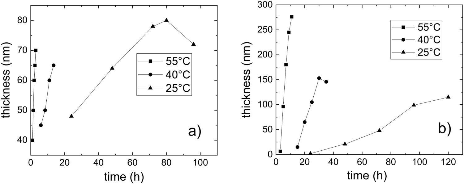
Rondiya et al. [129] reported a similar behaviour of the thickness as a function of temperature for the synthesis of CdS. Unlike the two previous works, they only modified the temperature, keeping constant the concentration of the chemical reagents, the pH of the solution, and the deposition time.
Growing rate
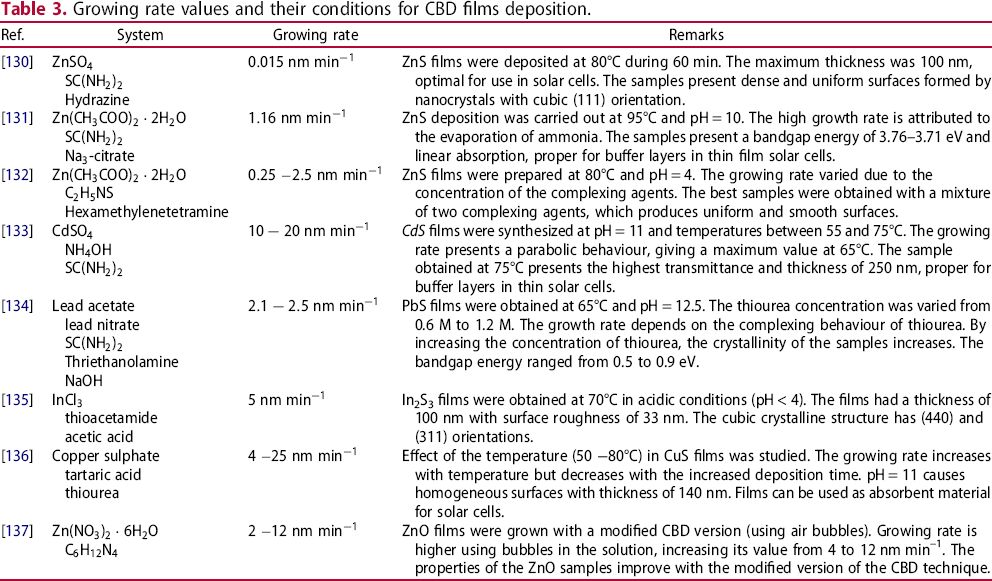
Growing rate values and their conditions for CBD films deposition.
Activation energy and order of the reaction
The growing rate (ν) depends on the temperature, concentration of the reagents and pH of the solution. If only the temperature (T) of the solution is varied during the deposition of the material, the relation between the growing rate and temperature can be estimated by means of the Arrhenius equation,
Activation energy (Ea
) values for the ZnS films reported by different research groups. Data were taken from Ref. [138].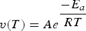
 is a constant that depends on the tank parameters,
 is the activation energy, and
 is the universal gas constant. From Equation (17), the value of the activation energy of the system can be obtained by calculating the slope of the linear relationship of the logarithm of the growing rate vs the reciprocal of the absolute temperature. The value of Ea
can explain the growth mechanism of the material. Figure 6 shows the values of the activation energy calculated by different groups for ZnS films.
is the universal gas constant. From Equation (17), the value of the activation energy of the system can be obtained by calculating the slope of the linear relationship of the logarithm of the growing rate vs the reciprocal of the absolute temperature. The value of Ea
can explain the growth mechanism of the material. Figure 6 shows the values of the activation energy calculated by different groups for ZnS films.
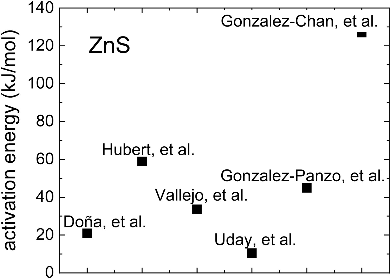
The differences on the Ea
values observed in Figure 6 can be explained in terms of the bath temperature and concentration of the chemical reagents. Doña and Herrero [139] reported that the growing process is limited by the adsorption of the complexing agent on the substrate. Hubert et al. [140] reported that the Ea
value (60°C to 90°C) is related to chemical reactions involving successive surface reactions with adsorbed intermediate. In other work, Vallejo et al. [141] determined that the low Ea
value obtained (50–80°C) indicates that the growing rate could be due to a physical process, such as diffusion or adsorption. Bhaskar et al. [142] determined that the growing rate is controlled predominantly by temperature instead of chemically controlled process given the low Ea
value of their system (30°C to 80°C). Gonzalez-Panzo et al. [143] and González-Chan et al. [138] not only determined the Ea
value in their respective experiments, but also determined the reaction order (δ) of the deposition as a function of the thiourea concentration, based on the modification of the Arrhenius equation,
Growth mechanisms
The growing mechanisms of the films through the CBD technique can be carried out by the ion-by-ion or by clusters [144]. In the ion-by-ion mechanism, the ions are free in the solution, which condense on the surface of the substrate to react and form the film. However, this process is not simple due to the release of ions in the solution. The particles can instantaneously precipitate without forming the nanolayer. To avoid this rapid precipitation, various complexing agents are used in the solution. On the other hand, the cluster mechanism requires the formation of preformed colloidal particles in the solution which are adsorbed on the substrate and form the film. For this, it is required the formation of a metallic hydroxide that will act as the colloidal particle. Nevertheless, it is difficult to identify the type of growth mechanism from the experiments. In several cases, there are depositions that involve various growing mechanisms. Readers can refer to section E in Supplementary Information where the growth mechanisms of some materials such as CdO, CdS, ZnS, PbSe and CuS are discussed in detail [145-154].
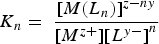
The algorithm for calculating the optimized chemical conditions for CBD
The algorithm to optimize the chemical conditions for films growing by the CBD technique is shown in Figure 7. This tool represents a generalized version of the algorithm for obtaining the species distribution diagrams (SDDs) and the solubility curves (SCs) of the ZnCl2-SC(NH2)2-NH4NO3-KOH deposition system proposed by Trejo-Ramos et al. [155]. The system is generalized as MCl2-SC(NH2)2-NH4NO3-KOH (M = Zn, Cd), and consists in the development and solving of equilibrium reactions in terms of the metallic ions M2+ and the respective mass and charge balances of the formed species (explained in Sections 2.3 and 2.4), to obtain the SDDs and the SCs for either the CdCl2-SC(NH2)2-NH4NO3-KOH and the ZnCl2-SC(NH2)2-NH4NO3-KOH systems. Readers are referred to section F of the Supplementary Information for the specific details of each step presented in Figure 7. Also, a detailed discussion of the use of SDDs and SCs for the study of ZnS, ZnO and Zn(OH)2 [156-181] are also presented at such section in the Supplementary Information.
Generalized algorithm for obtaining the SDDs and SCs for depositing M2+ (M = Zn, Cd) for CBD technique. a) to o) means the sequential steps for solution (reprinted from Ref. [155], with permission from Elsevier).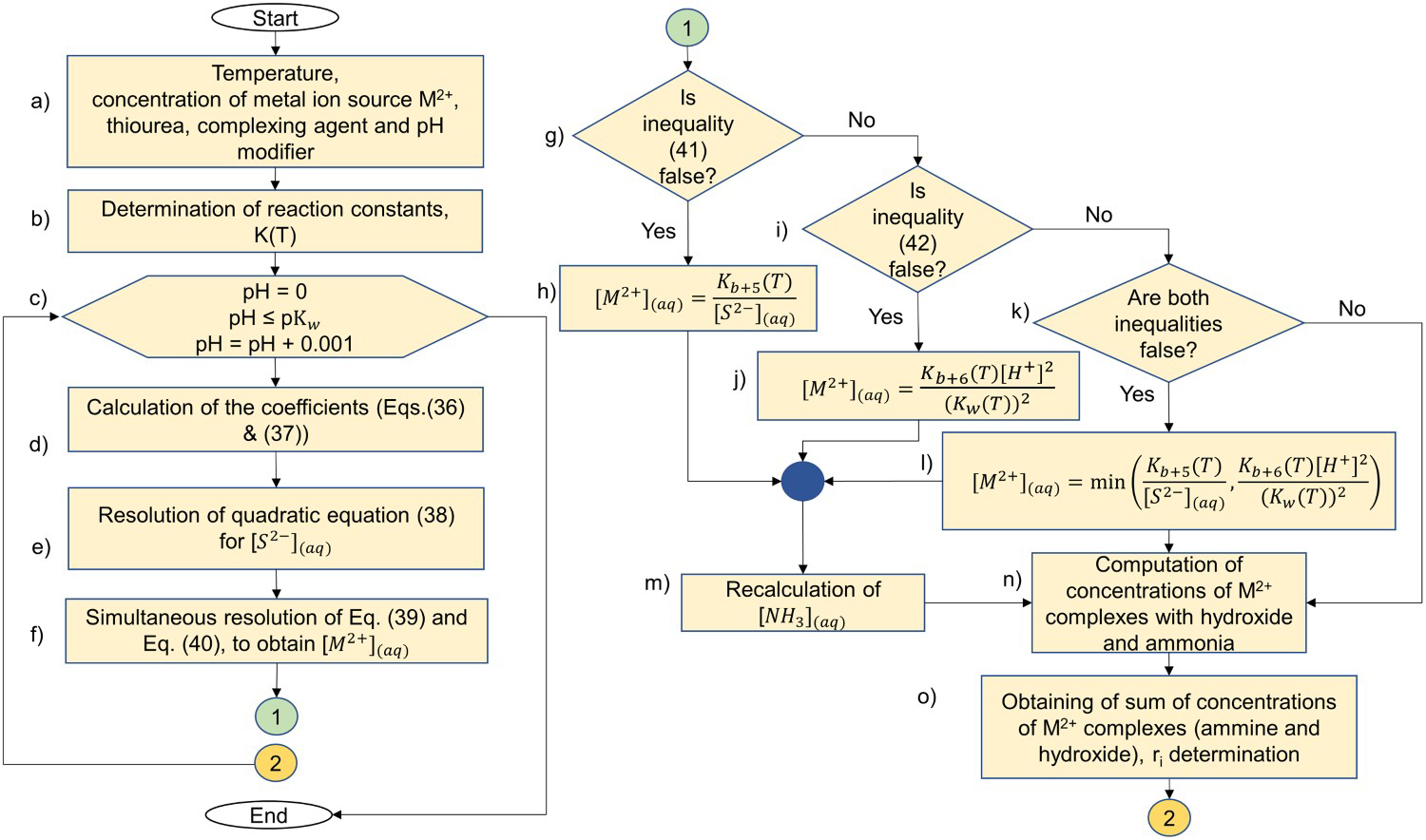
Some recent advances on chemically deposited materials
When binary or ternary thin film materials are prepared by the CBD technique, the properties of most interest for further applications are the morphology, the crystalline structure, the optical or electrical properties and the stoichiometry [182-191]. For solar cells applications, for example, large grain size and certain thickness value are useful for improving the efficiency [192,193]. The crystalline structure obtained on the deposited films can be correlated with possible contamination and polymorphism conditions. A high orientation or low intensity of not-expected X-ray diffraction peaks confirm a better crystalline structure or a reduction of the contaminants, respectively. On the other hand, the bandgap energy, absorbance, transmittance and reflectance are optical properties related with the quality of the deposited film, as well as with the stoichiometry [194]. In the following sections the use of low temperatures (room conditions) for the CBD and the generations of SDD and SC for some specific materials will be presented as recent topics on the CBD area.
Films deposition at room temperature
CdS films were deposited at relatively low temperature, 30°C, by Archbold et al. [195]. Authors used nitrogen gas bubbled over the substrates for 75 min. In a different study, Garadkar et al. [196] deposited CdS films by successive ionic layer absorption and reaction (SILAR) technique including cadmium acetate, thiourea and aqueous ammonia as chemical reagents. CdS presents a low solubility product, Ksp = 10−28. Recently, Wan et al. [197] reported an aqueous methodology to prepare CdS clusters from the CdCl2-KOH-CS(NH2)2 system and 3-mercarpotopropionic acid (MPA) as ligand at RT and pH = 11.7. Authors remark the presence of butylamine (BTA, CH3-(CH2)3-NH2) for assisting the thiourea decomposition in presence of CdCl2 for CdS clusters formation with an absorbance peak at 360 nm proper for quantum dots. Kadam et al. [198] reported formation of CdS-nanoflakes by precipitation technique at RT, useful for photocatalysis. The bandgap energy of 2.48 eV and the mixed cubic-hexagonal crystalline structure obtained are useful for catalytic materials under solar applications. In Ref. [199] CdS nanocrystals were deposited in aqueous solution at RT which permits to control the phase, size, and morphology of the nanocrystals. The sulphur (from thioacetamide) and cadmium ions are controlled via the pH in a wide range (1.5–10.5) of the solution and by means of ligands of ethylene-diamine-tetraacetic acid, sulfo-salicylic acid, and ethylenediamine to form precursor complexes.
In a proposal by our group, CdS films were prepared near RT (25 and 30°C) by using the CdCl2/NaOH/C2H4(NH2)2/CS(NH2)2 system using bubbling argon gas during deposition. Deposition times from 1.5 h to 4 h were required due to the low temperature used. In the reaction, CdCl2 is easily dissociated and reacts with the hydroxyl ions provided by the NaOH to form the cadmium hydroxides [200]. The CdS formation corresponds to the cluster mechanism explained in Section 3. Energy band gap and stoichiometry were analysed in terms of the presence of argon and as a function of the room temperatures used.
Zinc sulphide (ZnS) is the most appropriate and studied semiconductor in the last years for substituting CdS in the thin film devices given the damage of Cd to the environment [201,202]. ZnS has a higher bandgap energy value (3.72 eV) but its growth by the CBD technique is not as straightforward as that for the CdS. This is due to the higher value of its solubility product (Ksp = 10−25) in comparison with the CdS (Ksp = 10−28). In addition, the chemical reactions are highly dependent on the bath temperature and the chemical concentrations of the reagents; deposition time can be modified by changing these parameters. In this case, the SDDs and the SCs take a relevant role for obtaining the best chemical concentrations of the reagents to achieve the desirable material. A challenge for ZnS deposition is to grow it near room temperature conditions. Figure 8 shows the SDDs obtained at 25, 40, and 55°C for the ZnCl2-NH4NO3-KOH-CS(NH2)2 system. The shaded area shows the pH conditions under which ZnS can be synthesized with adequate properties for solar cells applications. The change of pH
SDDs obtained for the CBD-ZnS system at different solution temperatures. in the growth solution allows to estimate the quality of the deposited material; as the temperature increases,
 decreases, which results in a more stable deposition.
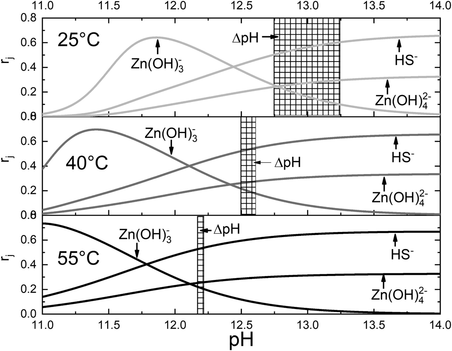
Figure 9 shows a typical thickness vs. time plot obtained for ZnS films deposition at 25°C. Three zones are observed: the induction, the growing, and the saturation zone.
Three zones of growth observed during CBD-ZnS deposition.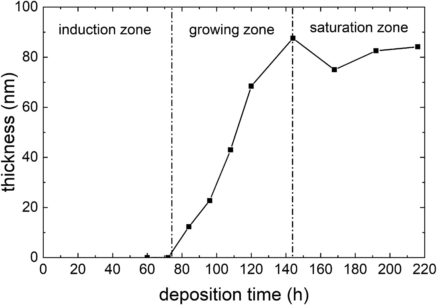
Kinetic parameters of ZnS synthesis at different temperatures.
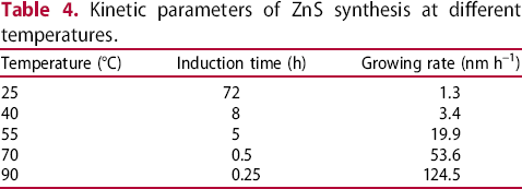
Figure 10 shows the surface micrographs for different magnifications of the CBD-ZnS films deposited at 25°C, 40°C, and 55°C. The grain size increases with the temperature. The Eg
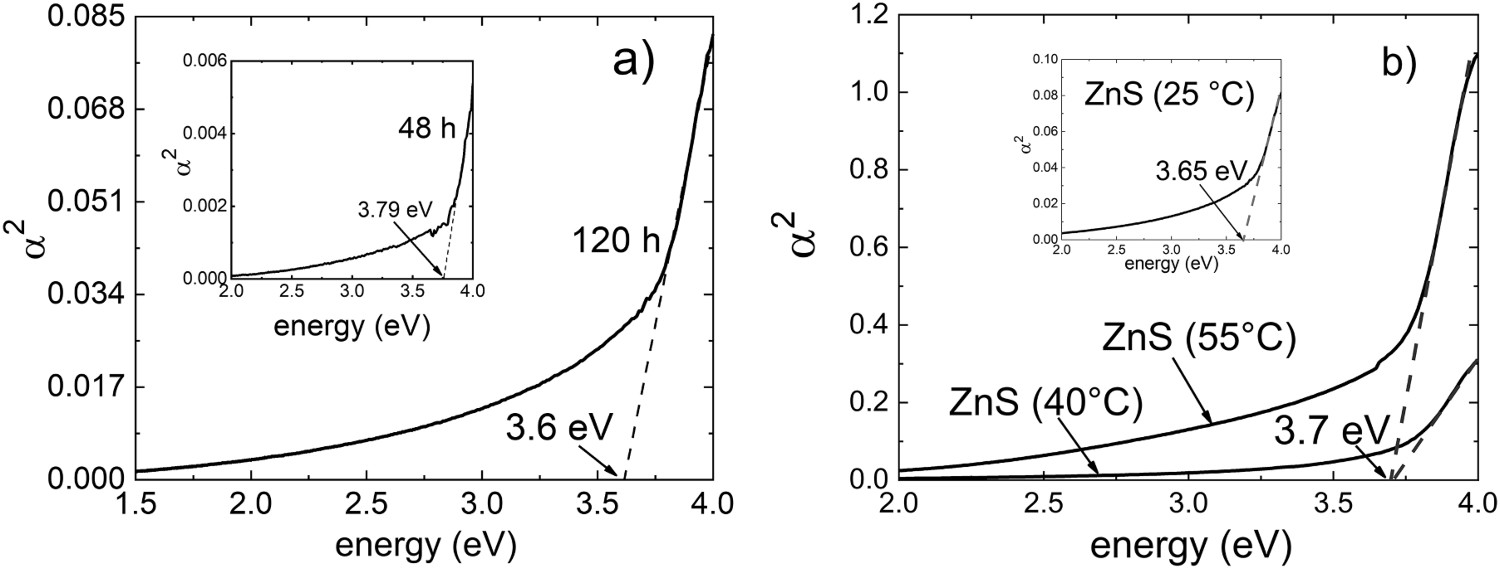
of the films was optically measured obtaining values of 3.60–3.79 eV as shown in Figure 11. The Eg
formation is shown for the films deposited at 25°C until to reach the 120 h of deposition. For this films, higher values of Eg
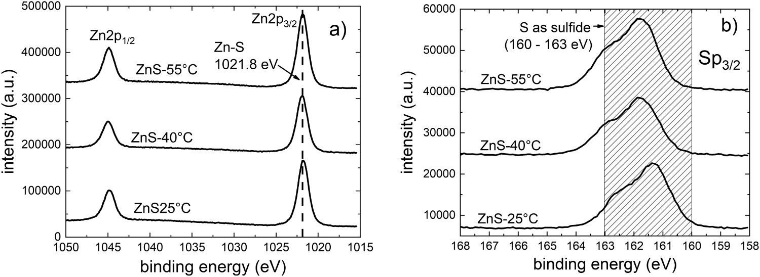
were measured; this is related to the very low thickness achieved which promotes a quantum confinement effect [203] (3.79 eV at 24 h). The XPS results (Figure 12) show the peaks of zinc (Znp3/2) and sulphur (Sp3/2). The elemental composition shows that the [Zn]/[S] at.-% ratio improves with temperature, obtaining values of 0.367, 0.428, and 0.906, for 25°C, 40°C, and 55°C, respectively. Zn deficiencies for films at 25°C and 40°C may be caused due to the presence of other compounds such as ZnO or Zn(OH)2.
SEM images of the CBD-ZnS films deposited with different temperatures during 120 h (50,000×) at 25°C, 35 h (10,000×) at 40°C, and 11 h (10,000×) at 55°C. Bandgap energy values of the CBD-ZnS films deposited at: (a) 25°C for different time deposition, (b) bandgap energy values obtained at 25, 40, and 55°C after final deposition time. XPS results of the Zn2p and Sp3/2 windows indicating Zn–S bonding's for the CBD-ZnS films deposited at different temperatures.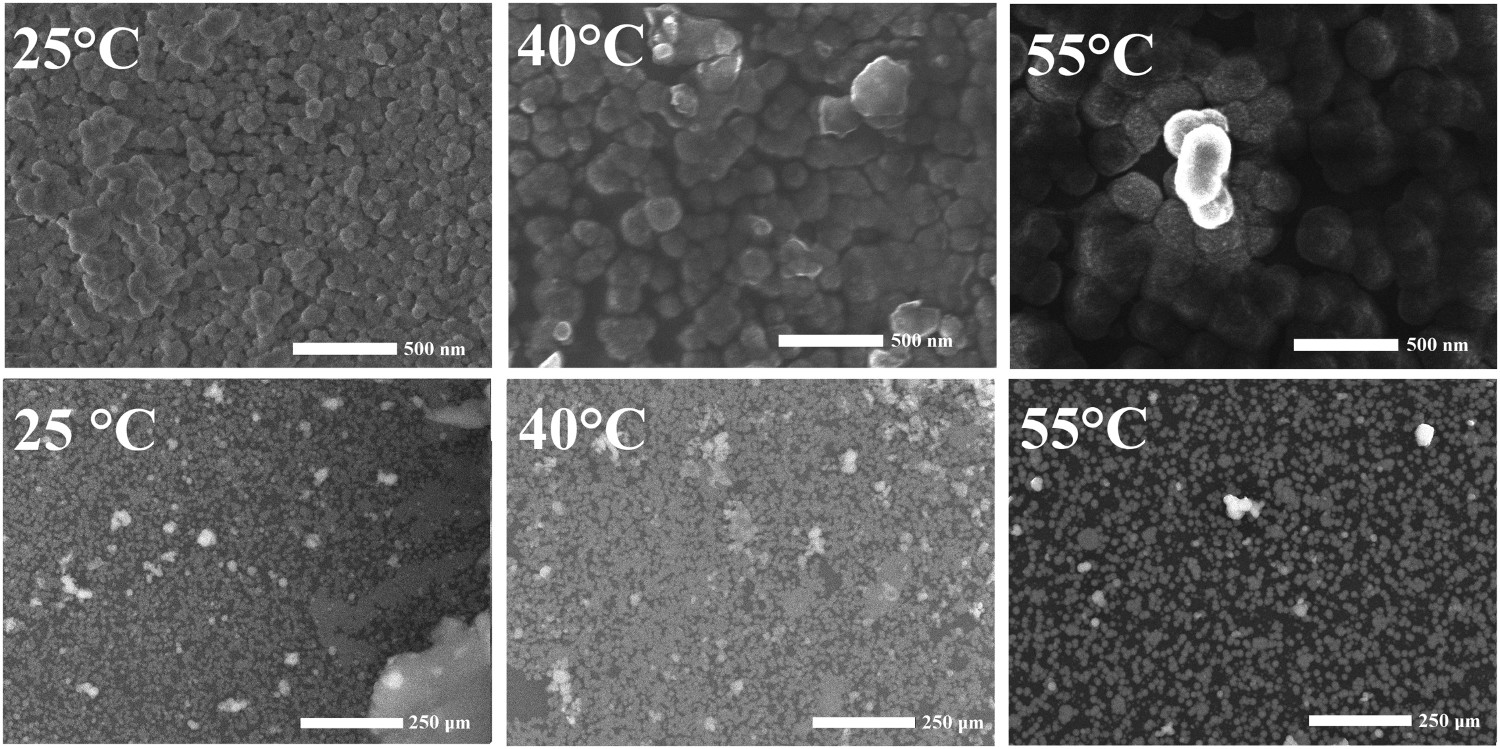
Use of SDDs and SCs for CBD deposition of ZnS, Zn(OH)2 and ZnO
A desired feature for ZnS deposition is to reduce the number of chemical reagents in order to simplify the number of chemical reactions. Thus, the use of the ZnCl2-KOH-CS(NH2)2 system, where the ammonium nitrate is not included, has been proposed [152]. Figure 13 shows the plot of the SDDs for this chemical condition determined at 40°C. The plot seems most simple, given that lower number of chemical reactions are involved for ZnS formation. The chemical reactions in this case are [204],
SDDs obtained for the ZnCl2-KOH-CS(NH2)2 system at 40°C. Ammonium nitrate is not included in the solution.


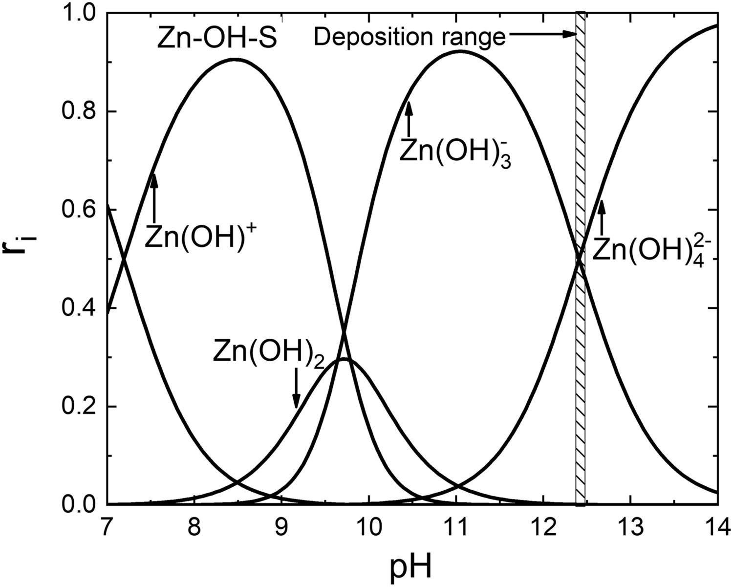
Zn2+ ions react with OH- ions to form some intermediate complexes. These complexes react with the S2– ions for form the ZnS, Equations (19)–(22). Analysing the other SDDs, the optimized pH value for ZnS deposition is showed by the vertical area marked at pH = 12.4; this is, the crossing point between the Zn(OH)3
– and Zn(OH)4
2– complex ions. The most probable chemical reactions forming the ZnS are,


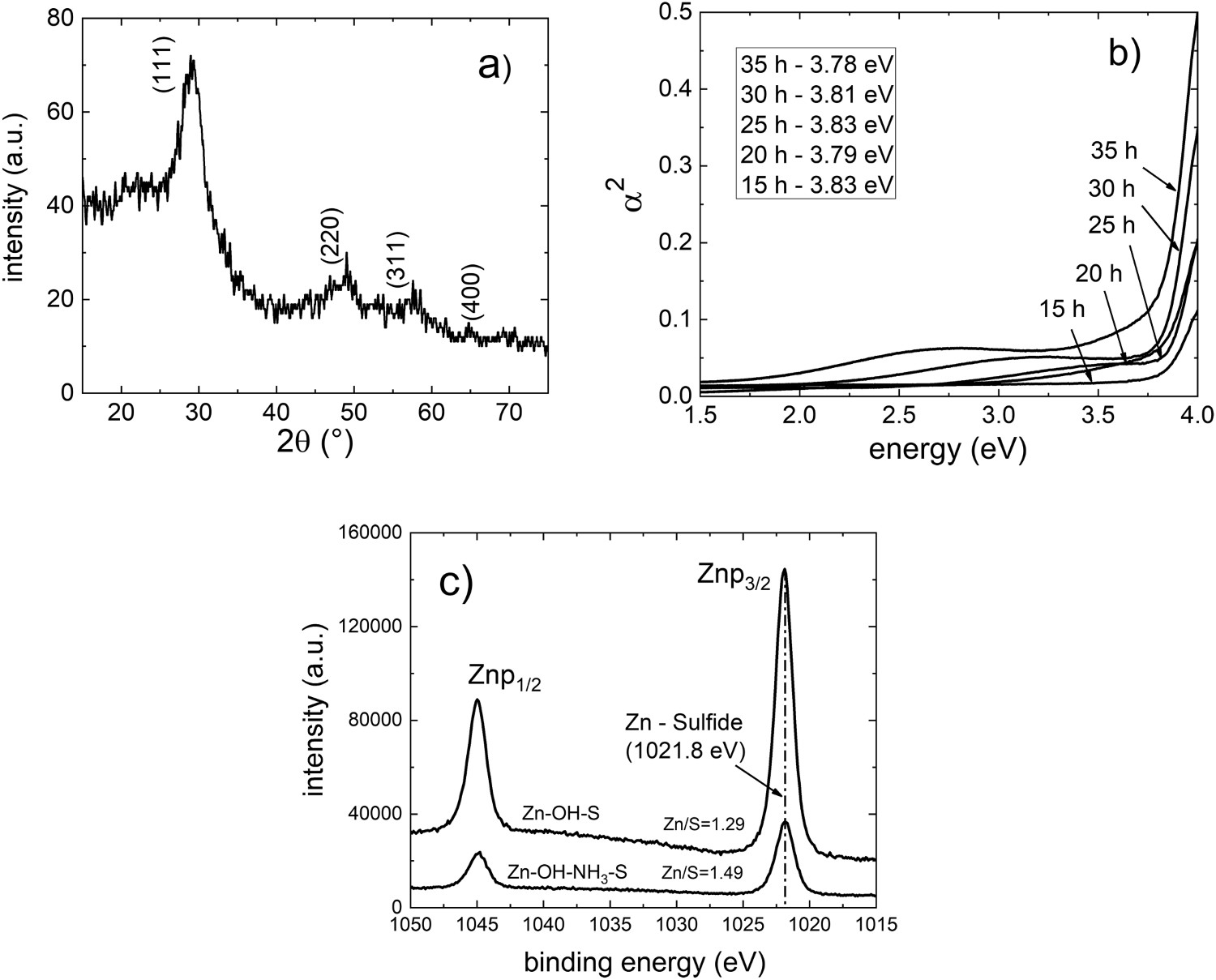
The most outstanding improvements of this methodology are observed in the crystalline structure (Figure 15(a)), where three diffraction peaks of the ZnS cubic structure were obtained, and a correct visualization of the absorption edge for obtaining the Eg
value (Figure 15(b)). It is important to note that all the obtained Eg
values are consistent with the values reported for ZnS. Figure 15(c) shows a comparison of the Znp3/2 peak as obtained by XPS for a system with and without ammonium nitrate. An increase in the intensity of the Zn peak can be noted when there is no ammonia in the solution. Given that Zn ions do not form ligands with this compound, a greater availability of these ions for obtaining hydroxide compounds lead to the formation of ZnS by means of Equations (23) and (24). Better stoichiometry was obtained for ZnS films deposited without ammonium nitrate.
Micrographs of the CBD-ZnS/glass films deposited at 40°C: (a) with and (b) without ammonium nitrate during 35 h. Scale bar is 1 μm. Reprinted from Ref. [152] with permission from Taylor and Francis. (a) Diffractogram of the CBD-ZnS films deposited in absence of ammonium nitrate during 35 h, (b) α2 vs energy plot for obtaining their bandgap energy, (c) Zn ligands measured by XPS for the CBD-ZnS films obtained with and without ammonium nitrate.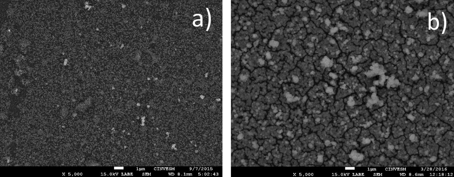
The formation of the zinc-hydroxide, Zn(OH)2, is sometimes undesirable and appears as a consequence of non-appropriate chemical conditions of the solution when ZnS or ZnO are deposited by CBD [205,206]. Some authors report the formation as an impurity generated along with the desirable compound, highlighting the difficulty of its reduction or elimination [207,208]. With the use of the SDDs and the SCs, it is possible to deposit only this compound or to avoid its formation when another compound is wanted to be deposited. Figure 16 shows the SDDs for the ZnSO4-KOH-NH4NO3 system used for obtaining Zn(OH)2 at RT for certain reagent concentrations. According to Figure 16, the main differences for the synthesis of Zn(OH)2 and ZnS are the lack of thiourea as a chemical reagent in the solution and the deposition range that is located on the left side of the crossing point between Zn(OH)3
- and Zn(OH)4
−2. Thus, the probability for depositing Zn(OH)2 is higher due to the wide pH range (from 10 to 12.8) of the precursor Zn(OH)3
-. At these chemical conditions, the solution suffers important changes of the pH during the deposition time of 120 h and room temperature condition (25°C).
SDDs and conditions for obtaining the Zn(OH)2 compound at room temperature (25°C).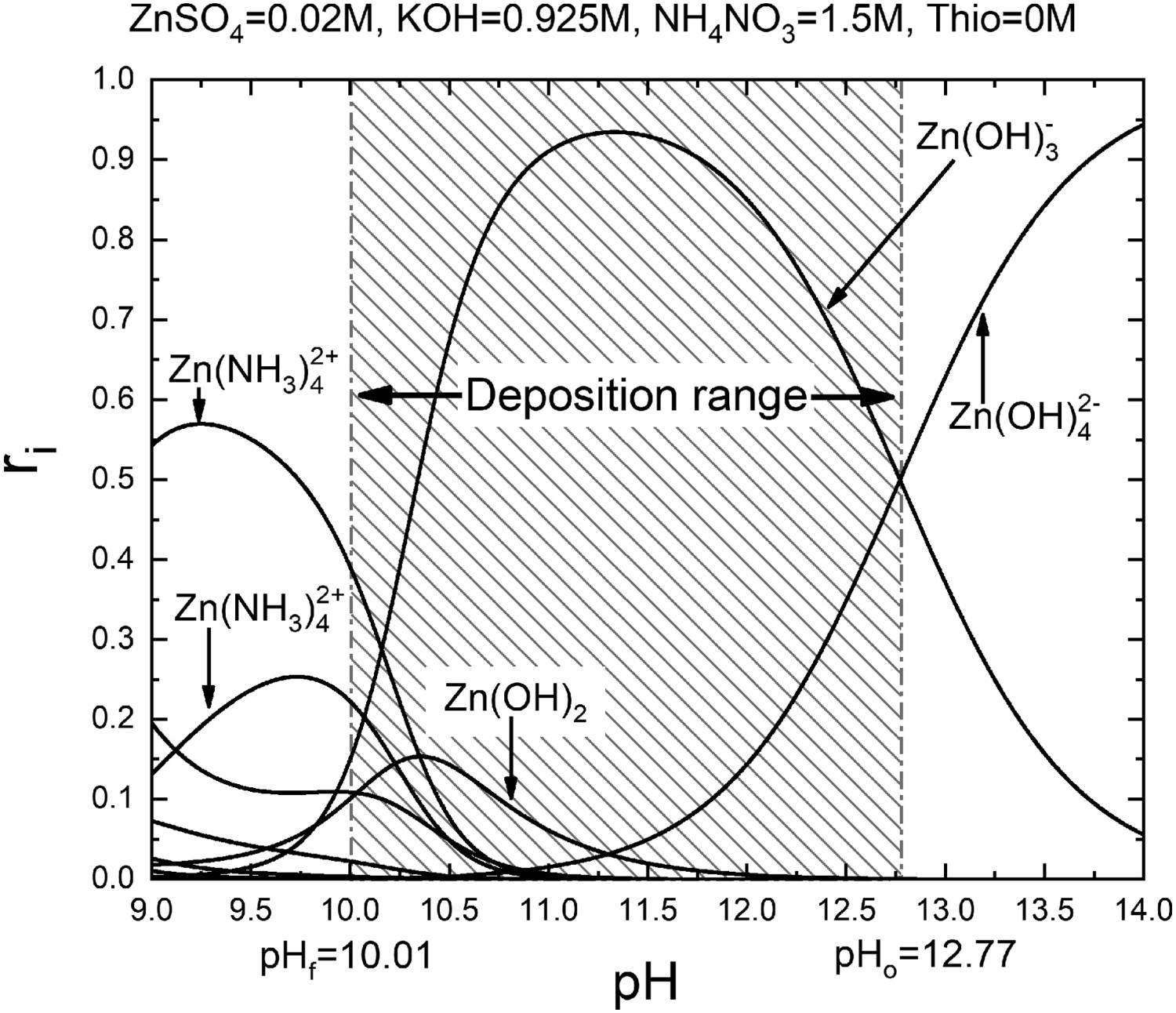
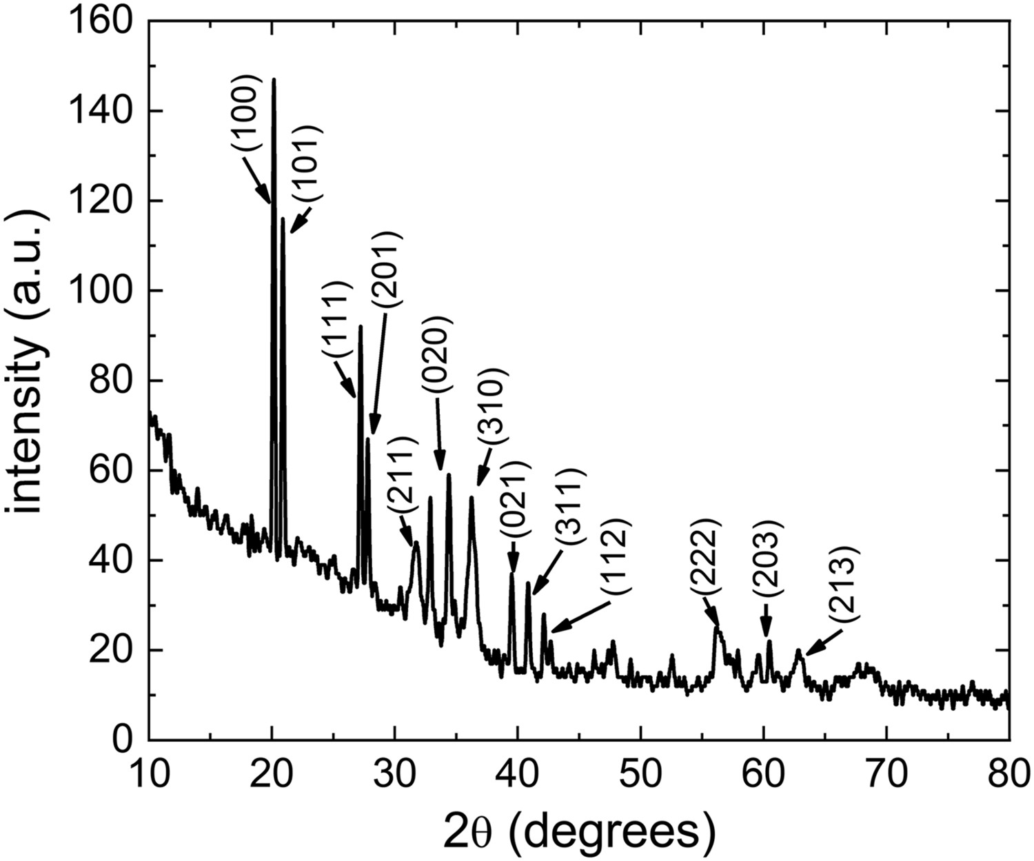
Figure 17 shows the SEM images of the formed Zn(OH)2 crystals at these conditions [35, 209]. Well defined planes with good crystalline structure of the compound were observed, according to the X-ray diffraction peaks observed in Figure 18 [JCPDS 38-0385]. In addition, from the elemental concentration analysis by punctual EDS on the formed crystals only Zn (19 at.%) and O (81 at.%) were detected.
Crystals of Zn(OH)2 deposited at chemical conditions in Fig. 31 (reprinted from Ref. [155], with permission from Elsevier). Scale bar: left 10 μm and right 1 μm. XRD obtained from the Zn(OH)2 chemically deposited.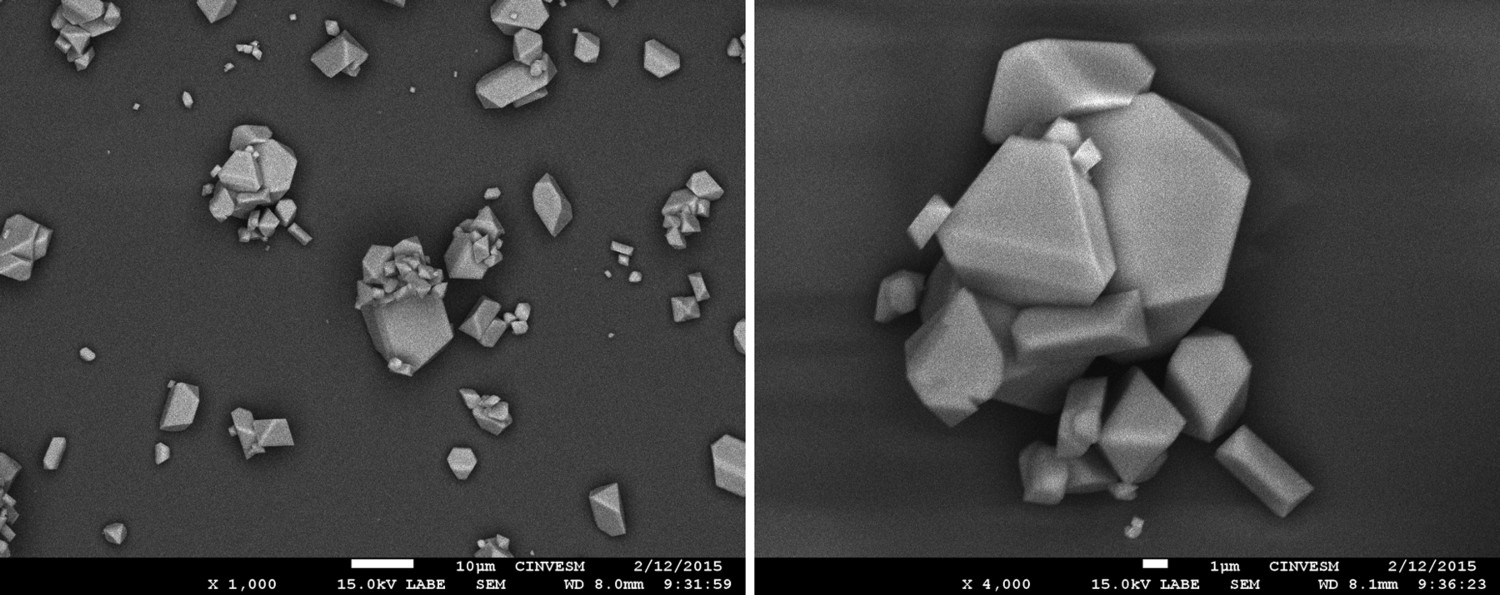
Metallic oxides are normally grown at high temperatures by following the favourable oxidation process [210,211]. When a metallic oxide is prepared by the CBD technique, a post-annealing treatment with high temperatures after deposition is normally realized [212,213]. Thus, a challenge in the CBD technique is to deposit in a controllable way the oxide films at RT. This is possible if the chemical conditions are selected from the SDDs and SCs and the adequate concentrations of the chemical reagents and the temperature.
As an example, ZnO films were deposited on glass substrates at RT. The SDDs obtained with the ZnCl2-KOH-NH4NO3 system were used according to Figure 19.
SDDs for CBD-ZnO deposition, during 250 min. Shadowed area gives the pH condition for ZnO deposition.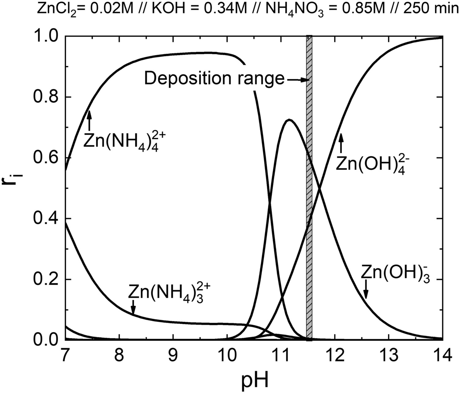
The shadowed area is the pH of the solution used for ZnO formation. Observe that the used pH value is lower than the value of the crossing point of the Zn(OH)3
– and the Zn(OH)4
2– used for Zn(OH)2 formation. At these conditions, the ZnO grows as well-defined nanowires on the substrate surface (Figure 20) [214]. Thinner and more intense XRD peaks were obtained from the ZnO nanowires.
Nanowires of ZnO deposited by the CBD technique at room temperature. Scale bar is 1 μm.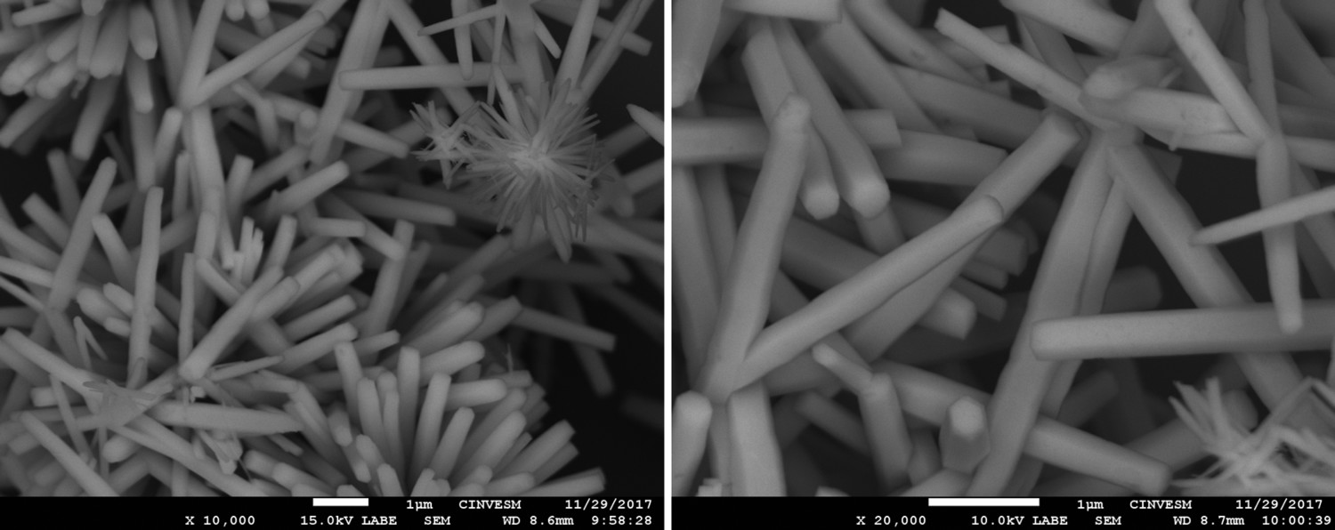
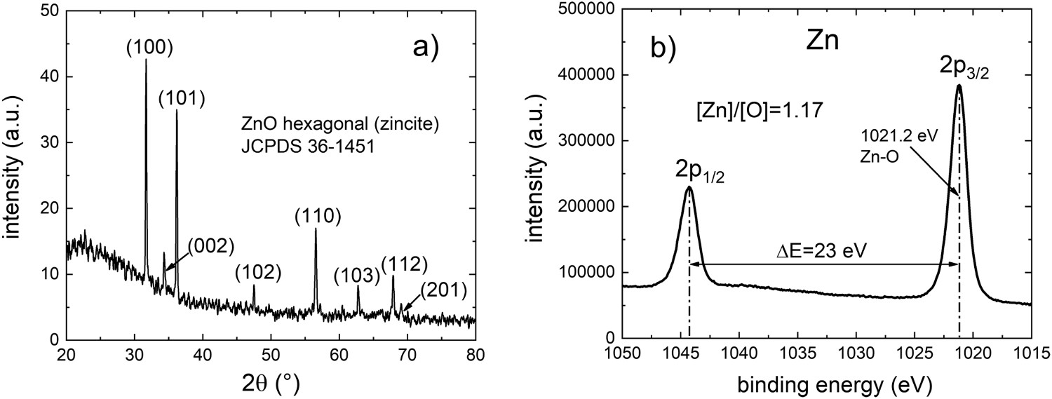
The hexagonal crystalline structure corresponding to the zincite dominate on the nanowires, with (111) as preferential orientation (Figure 21(a)). The crystallite size D measured with the Debye–Scherrer equation,
(a) Diffraction patterns of the CBD-ZnO nanowires deposited at RT, (b) window of Zn from the XPS results measured on these nanowires.
Conclusions
The preparation of nanomaterials films by aqueous deposition is a low cost and easy methodology for applications in nanotechnology. This deposition technique is now widely used for different researchers given the better understanding for controlling the growing mechanisms. The species distribution diagrams and the solubility curves of the materials to be deposited have attracted more attention due to their assessment to find the optimized growing conditions, and for avoiding contaminants or undesirable compounds. This important contribution requires to be adapted for each compound to be prepared. The methodology requires to know all the possible chemical reactions involved depending on the chemical reagents used for forming the growing solution. New challenges and open opportunities are waiting for the use of this technique. Fortunately, the physicochemical characterization techniques help to clarify the properties of the deposited materials at the predicted conditions, confirming the utility of this aqueous technique. A developed algorithm based on the chemical parameters permits to select the optimal chemical conditions before deposition. This represents a relevant contribution for reducing research time, materials, and faults during materials deposition. Some results for preparing films of CdS, ZnS, ZnO, and Zn(OH)2 in a controllable way were discussed in this review, making emphasis on the obtained morphology, crystalline structure, stoichiometry, and optical parameters of the prepared material. A new field in the materials science has been opened for preparing compounds by aqueous solution and a lot of work is still required for preparing specific materials with determined properties, but a novel and useful methodology to carry out such a task has been here presented and reviewed.
Footnotes
Acknowledgements
Authors want to acknowledge Dra. Patricia Quintana for the access to LANNBIO facilities, Dr. Víctor Rejón for the SEM measurements, M.Sc. Daniel Aguilar Treviño for the XRD analysis and Wilian Cauich for the XPS analysis.