
Abstract
The WC–12Co coatings were deposited on SS 410 substrates using a high-velocity oxygen fuel (HVOF) process and the coatings were heat-treated at 750°C for 1 h in argon environment. Further, the coatings were subjected to cryogenic treatment for 1, 2, 8 and 24 h, and its influence on the reciprocating sliding wear and corrosion characteristics was studied. The structural changes in the coatings after post-treatment were assessed by X-ray diffraction analysis and Raman spectroscopy. Microhardness was improved for cryogenically treated coatings due to the α-Co transformation into ϵ-Co. Cryogenic treatment duration was not having a significant effect on the microhardness values. However, the specific wear rate was influenced by the cryogenic treatment duration. Also, corrosion resistance was increased with the increased cryogenic treatment duration. The protective layers consisting of WO3 and Co3O4 phases formed during the cryogenic treatment are attributed to the improved corrosion resistance of the coatings.
Keywords
Introduction
Carbide-based thermal spray coatings are mostly used in wear and corrosion resistance applications in the area of automotive, aerospace, power plant, oil, and gas, petrochemical plants, drilling, mining operation, etc. [1,2]. Carbide coatings can be deposited through the plasma spray process but as it possesses higher flame temperature and low particle velocity, the chances of loss of carbon are more, which results in the formation of undesirable new phases and the presence of porosity is also on the higher side [3]. However, the recent thermal spraying processes such as high-velocity oxygen fuel (HVOF) and air fuel (HVAF) have successfully overcome the limitations of the plasma spray process by minimizing the porosity and the decarburization of the coatings as they work at lower flame temperatures and higher particle velocity [3–5]. In the automotive and aerospace industries, WC–Co coatings have been extensively employed to develop wear-resisting surfaces as a substitute for chromium-based hard coatings [6–8]. The WC–Co coatings are mostly utilized where wear resistance is essential, but still, can be considered for severe corrosion resistance applications [9]. The decarburization of the WC reduces the wear resistance [10]. Therefore, post-coating treatments such as laser remelting or heat treatments are required to promote the quality of the coatings which leads to densification and change of the existing phases in the coatings.
Post-heat treatment has a significant impact on the residual stresses present in the as-sprayed coatings and improves the coatings’ hardness and adhesive strength due to the interdiffusion phenomenon at the coating and the substrate interface [11,12]. The wear resistance and hardness of the coatings are reported as increased along with the increase in the heat treatment temperature in air and nitrogen gas environments. However, heat treatment carried out in the air results in the development of brittle oxide phases that leads to micro-cracking within the coating, which causes the brittle fracture of the coatings during the wear tests. The presence of nitrogen helps to reduce the influence of oxygen, as a result, the formation of the oxide phases hinders which leads to improvement in the wear resistance of the heat-treated coatings [13]. Hou et al. reported that up to 700°C heat treatment temperature, the microhardness and wear resistance of the WC-based coatings increase. Beyond that, the properties deteriorate with an increase in temperature [14]. The formation of some brittle η-carbide phases takes place at higher temperatures, which leads to an increase in hardness and decreased toughness of the coatings. Asl et al. found that after heat treatment, the wear resistance of the coatings decreased as the heat treatment temperature increased from 650°C to 1100°C and concluded that fracture toughness of the coatings has a significant effect on the wear resistance of the coatings [15]. Gallego et al. reported that heat-treatment of WC-based coatings at a lower temperature 350°C, provides better wear resistance than at a higher heat treatment temperature due to the microstructural defects related to the oxidation during heat treatment [16]. So, heat treatment should be performed in an inert environment or vacuum to reduce the chances of oxidation that leads to deterioration of the wear resistance of the coatings [2,5,13,16].
Cryogenic treatment is a well-known process where the treatment temperature is kept below −120°C. Cryogenic treatment has a significant effect on the mechanical characteristics of the WC–Co coatings. Gonzalez et al. evaluated the effect of cryogenic treatment on the erosion behaviour of the WC-based coatings and observed that cryogenically treated coatings have better erosion wear resistance at lower impingement angles [17]. Wang et al. investigated the wear resistance of WC–Co coatings subjected to cryogenic treatment and observed that η-carbide formation and transformation of α-Co to ϵ-Co phase enhanced the wear resistance [18]. According to Govande et al., cryogenic treatment reduces the friction coefficient of the coatings and also increases the microhardness [19]. Formation of η-carbide phases after cryogenic treatment is responsible for the improvement in microhardness of the coatings that leads to the increased wear resistance of the coatings [20].
Thermally sprayed WC–Co coatings possess different corrosion mechanisms due to different oxide phases, cracks and porosity and also due to partially dissolved carbide particles in the matrix [21]. Picas et al. evaluated the effect of the oxygen-to-fuel ratio on the corrosion resistance of WC-based coatings and discovered that the porosity of the coatings decreases with the increased oxygen-to-fuel ratio, thereby decreasing the corrosion rate [22]. Increasing the coating thickness helps to reduce the porosity and to enhance the corrosion resistance [23]. The reported literature shows, in thermal spray coatings, porosity plays a major role in improving corrosion performance. Azizpour et al. examined the role of particle temperature on the corrosion behavior of the WC–Co coatings. The coatings with highest porosity exhibit higher corrosion resistance than the other tested coatings because of the presence of higher amount of amorphous-nano-crystalline phases. Hence, the corrosion resistance was affected by the quantity of the amorphous-nano-crystalline phases present in the coatings [2]. Arunnellaiappan et al. studied the corrosion behaviour of WC–Co coatings and enhanced corrosion resistance was reported. Further, it is concluded that the dissolution of the Co binder in the coating composition is responsible for the increased corrosion current density [24]. Pishva et al. studied the effect of grinding on the corrosion resistance of the HVOF-sprayed WC-based coatings and found that an increase in the depth of cut increases the current density of the coatings which may be due to the increase in pores and microcracks on the grounded surface [25].
Some of the previous studies reported the effect of post-treatment such as heat treatment and cryogenic treatment on the corrosion behaviour of the coatings. Asl et al. heat-treated WC–17Co coatings at 1100°C and studied the corrosion characteristics of the coatings. The formation of more η-carbides (Co3W3C, Co6W4C Co6W6C, etc.) was seen in the heat-treated coatings with the reduction in WC peak intensity. The corrosion resistance of the coatings after heat treatment was decreased due to different types of crystallographic defects that occurred in some of the η-carbides which are prone to corrosion. Whereas the as-produced coatings have an amorphous structure and lower defects which enhanced the corrosion performance of the coatings [21]. According to Reddy et al., the formation of the micro-cracks in the heat-treated coating is due to the thermal coefficient of expansion mismatch between the substrate and the coatings and the second is the formation of the carbide phases during vacuum heat treatment. These two factors were found to be significant to influence the corrosion resistance of the heat-treated coatings [26]. The enhanced corrosion resistance due to the formation of more η-carbides at higher heat treatment temperatures as reported by Reddy et al. [26] is contrary to the finding of Asl et al. [21]. Bricín et al. studied the effect of cryogenic treatment on the corrosion behaviour of the WC–Co inserts and reported that for fine grain cemented carbides, the increased amount in ϵ-Co phase and change in micro-stresses after deep cryogenic treatment leads to an increase in the corrosion resistance [27].
Cryogenic treatment increases wear resistance and also reduces the residual stresses present in the cemented carbides. Densification of the cobalt matrix by changing the FCC structure to the HCP structure has been observed after cryogenic treatment. The formation of fine η-carbide phases after cryogenic treatment leads to increased hardness, mechanical strength, better wear resistance and corrosion performance. However, still there are limited studies reported on investigating the effect of cryogenic treatment on the wear characteristics of the thermally coated WC–Co coatings. To the authors’ knowledge, no information is available on using cryogenic treatment to enhance the corrosion performance of the thermally sprayed WC–Co coatings. Hence, in the current research work, the influence of deep cryogenic treatment (CT) on the wear and corrosion performance of WC–12Co coatings produced by thermal spraying has been investigated. The combined effect of heat treatment followed by deep cryogenic treatment (duplex treatment) on the wear and corrosion performance of the coatings was also investigated.
Materials and methods
HVOLF process parameters.
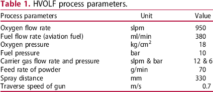
The coatings were prepared on the samples of size 20 mm ×20 mm for the wear and corrosion studies. The ball-on-plate configuration was utilized to investigate the wear characteristics of coatings against the alumina ball of 6 mm diameter. Tests were conducted with 10 mm stroke length and by applying a constant load of 30 N at a frequency of 5 Hz for a distance of 500 m. The wear tests were carried out on the as-deposited coatings and the measured surface roughness (Ra) value is 3.35 μm. The corrosion behavior of AD, HT, CT and duplex-treated coatings was evaluated by using a three-electrode electrochemical setup (CH Instruments, Model 604E). Graphite was used as the counter electrode, saturated calomel electrode was used as the reference electrode, and coated sample as the working electrode for the corrosion test. A 3.5-wt-% NaCl solution was used as the electrolyte for conducting the corrosion tests. The potentiodynamic polarization technique was used to measure the corrosion potential (Ecorr) and current density (Icorr) of the coatings. Coatings potential was scanned from –1 V to –0.2 V with a scanning rate of 1 mV/s. The flat corrosion cell has 1 cm diameter opening through which the sample was exposed to the electrolyte (sealed with leakage-proof rubber O-ring). The specific surface area of the workpiece exposed to the electrolyte was 0.785 cm2. The samples were allowed to establish OCP (open circuit potential) for 1800 s before the polarization testing to acquire the steady potential. The Raman spectroscopy analysis was carried out on the corroded samples with a 532 nm laser wavelength. To ensure consistency in the results, all electrochemical tests were performed at ambient temperature.
Results and discussion
Microstructure characterization
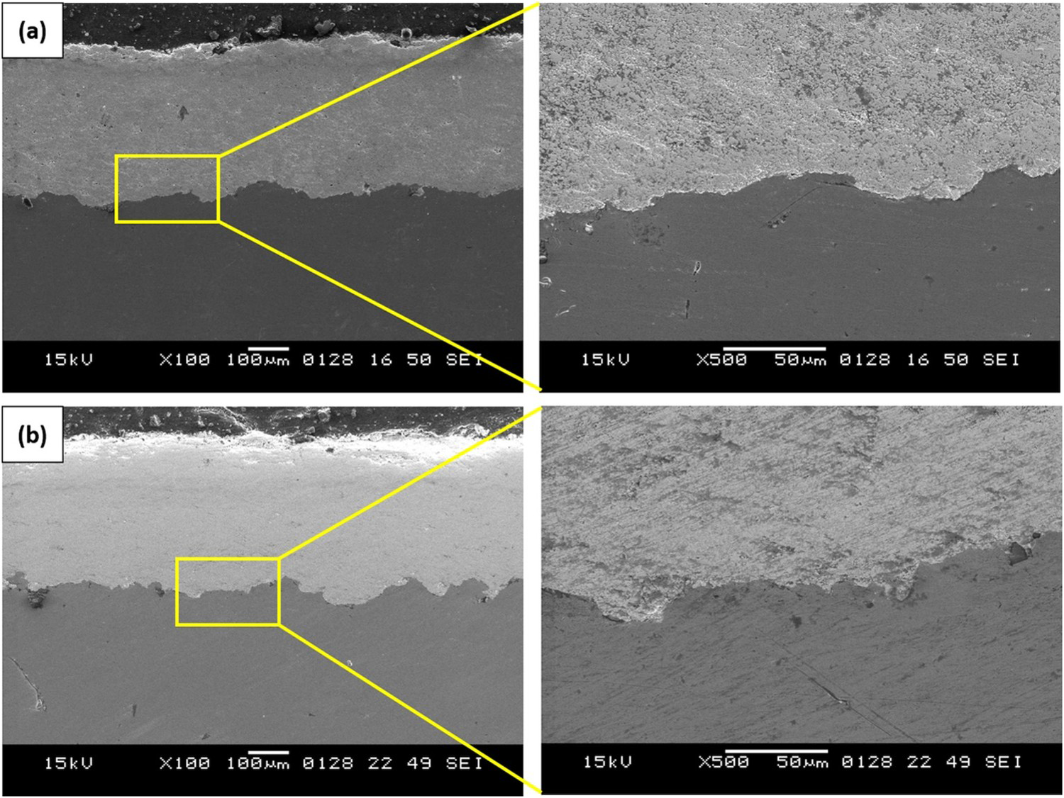
Figures 1(a) and (b) present the SEM image of the coating powder. The particles are majorly observed with spherical morphology having a near size of 15–45 μm. Figures 1(c) and (d) show the cross-sectional views of the coatings which display a dense structure mechanically bonded with the substrate. However, some pores have existed in the coatings which can be observed from the cross-section image. The porosity for as-deposited coating was found to be 1.48% which is lower and is in the typical range of the HVOF sprayed coatings. Nearly 370 μm thick coating was measured for the as-deposited coatings. It was observed that the WC particles are evenly dispersed throughout the metallic matrix, which is nearly blocky and angular in shape. Figures 2(a) and (b) show the cross-sectional images of the coatings obtained after cryogenic treatment and duplex treatment. It was evident from these images that the coating-substrate interface was intact and free from cracks.
SEM image of (a) WC–12Co powder, (b) magnified view of WC–12Co powder, (c) cross-sectional view of the as-deposited coating and (d) magnified view of the coating. Cross-sectional SEM images of the coatings after (a) 24 h cryogenic treatment and (b) 24 h duplex treatment (heat treatment followed by 24 h cryogenic treatment).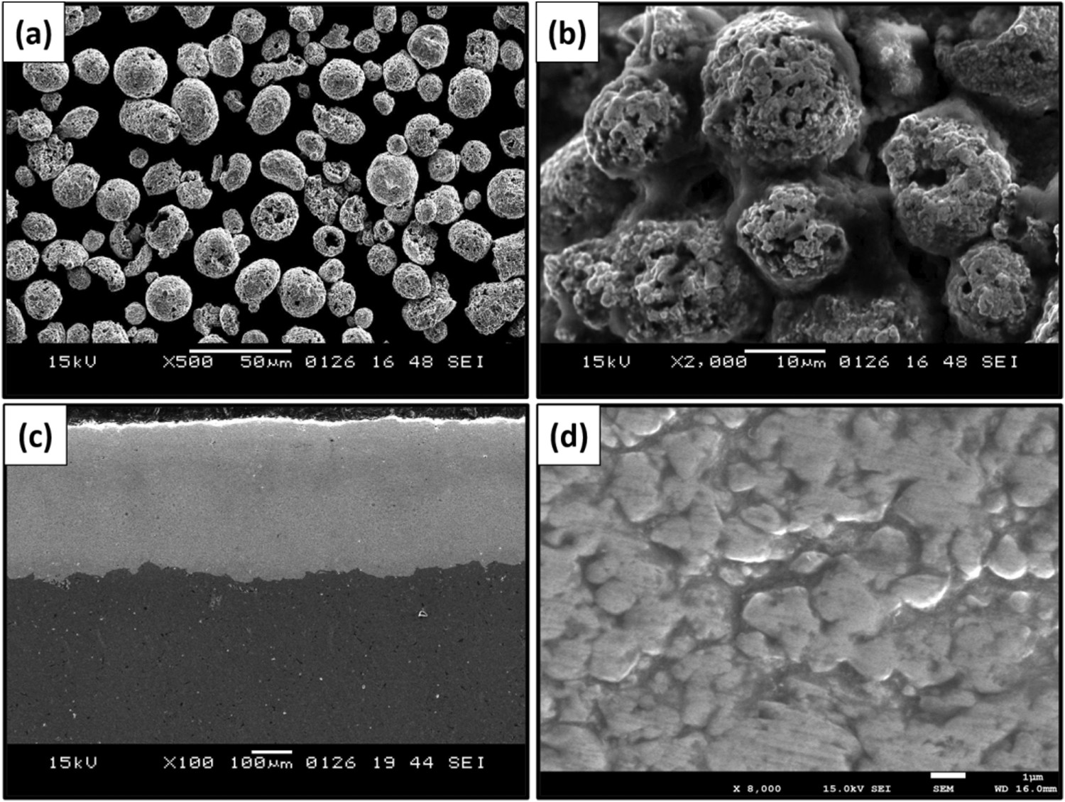
Structural characterization and microhardness
Figure 3 depicts the XRD pattern of the WC–12Co powder, as-deposited, heat-treated and cryogenically treated coatings. The WC–12Co powder primarily contains the WC phase along with the α-Co peaks. In the as-deposited coating, WC and W2C are the two phases majorly identified. Additionally, Co3W3C phase was also found for the as-deposited coatings. These two phases W2C and Co3W3C suggest the occurrence of decarburization during the coating deposition. The cemented carbide contains two different crystal structures of the Co phase, i.e. ϵ-Co with HCP structure and α-Co phase with FCC structure. It is known that below 417°C temperature, the cobalt presents in the ϵ-Co phase whereas, above 417°C temperature, the Co presents in the α-Co phase. The ϵ-Co phase has fewer slip systems than the α-Co phase and hence, the ϵ-Co phase is hard to deform and also exhibits higher strength and hardness [18]. The α-Co to ϵ-Co transformation happens after the cryogenic treatment [28,29]. From the XRD analysis, it can be observed that after cryogenic treatment, the amount of ϵ-Co increased as the cryogenic treatment duration increased. It is known that cryogenic treatment helps in the densification of the matrix because when the temperature is decreased, the metallic matrix experiences contraction behaviour. This contraction is enough for producing internal compressive stresses in the metallic matrix of the alloys such as WC–Co [17,29,30]. However, there is almost no change in the WC and W2C phases observed with the cryogenic soaking duration. Furthermore, cryogenic treatment leads to the development of fine η-carbides that also contributes to the enhancement of the hardness of the coatings [18]. The W2C phase intensity was decreased for the heat-treated coatings due to the formation of more η-carbide phases. In all the cryogenic treated samples, WC, W2C and η-carbides (Co3W3C, Co6W6C, Co2W4C) phases were noticed along with α-Co and ϵ-Co.
XRD patterns of the (a) WC–12Co powder, (b) as-deposited coating, (c–f) cryogenically treated coatings for the duration of 1, 2, 8, 24 h, (g) heat-treated coating and (h–k) duplex-treated coatings for the duration of 1, 2, 8, 24 h.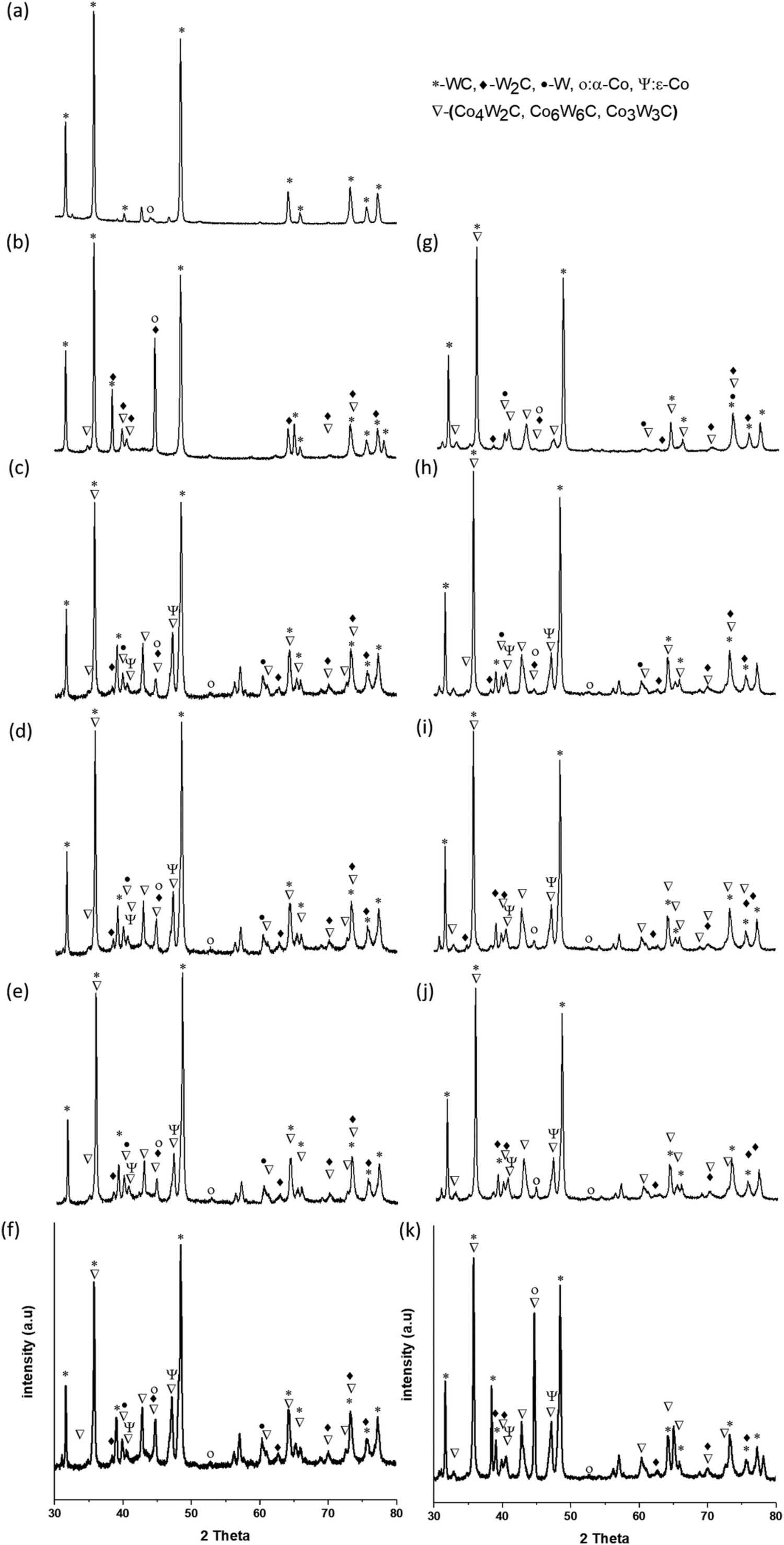
Figure 4 depicts the microhardness of the AD and HT samples along with CT and duplex-treated samples at different cryogenic treatment duration. The as-deposited coatings microhardness was measured as 1046 ± 34 HV0.3. The microhardness was increased to 1411 ± 92 HV0.3, 1434 ± 73 HV0.3, 1379 ± 90 HV0.3 and 1372 ± 75 HV0.3 after cryogenic treatment for 1, 2, 8 and 24 h respectively. This increment in the hardness of the coating was due to the development of η-carbides and densification of the cobalt matrix with the presence of more amount of the ϵ-Co phase. For CT coatings, the cryogenic treatment duration does not show any significant effect on the hardness. After heat treatment, the hardness was increased to 1501 ± 41 HV0.3. The formation of the secondary carbides is responsible to enhance the microhardness of the as-deposited coatings after the heat treatment [4,5]. Whereas duplex-treated coatings do not show any significant impact on the microhardness of the coatings due to the stabilization of the phases after heat treatment. Previous research suggests that soaking duration does not significantly affect the hardness, as also observed in the current results [28,29].
Microhardness of the as-deposited, heat-treated coating, cryogenically treated and duplex-treated coatings with different cryogenic treatment duration.
Wear characteristics
Figure 5 presents the comparison of COF values for the tested coatings. The AD and CT coatings initially show a rise in the COF curve as seen in Figure 5(a), due to the initial high asperities in contact with the counter ball. As the wear test proceeds, the COF curve seems to be decreasing for all the coatings because of the increased real contact area between the counter ball and the coatings due to a reduction in the asperities [31]. As compared to the cryogenically treated coatings, the as-deposited coating has lower COF. When comparing the COF of the samples with different cryogenic treatment duration, the sample with a higher cryogenic treatment duration (24 h) provides a lower COF. The formation of more η-carbides helps to reduce the COF of the coatings [18,28]. The 8 CT and 24 CT coatings have some fluctuations in the COF curve, and these fluctuations can be attributed to the removal of the splat or removal of oxide layers which exposed the beneath surface to the counter ball. Figure 5(b) shows the COF for HT and the duplex-treated coatings for different cryogenic treatment duration. For HT coating, the COF curve was found to be decreasing after reaching a value of 0.4, and after 1500 s, the COF curve tends to be stabilized to a value of around 0.3. For all the cryogenically treated coatings, a similar rise and fall of the curve were observed as that of the heat-treated coatings, but the COF value was observed as higher than HT coating. After the wear test was completed for 1000 s, the COF for all the cryogenically treated coatings was observed to be stable around a value of 0.4. The increase in cryogenic soaking duration leads to cobalt transformation that results in enhanced COF of the coatings and this enhancement is related to the binder matrix phase crystal structure. No significant variation in the COF curve of the duplex-treated coating was observed for different cryogenic treatment duration.
The coefficient of friction curves for (a) AD and CT coatings, (b) HT and duplex-treated (heat treatment followed by cryogenic treatment) coatings.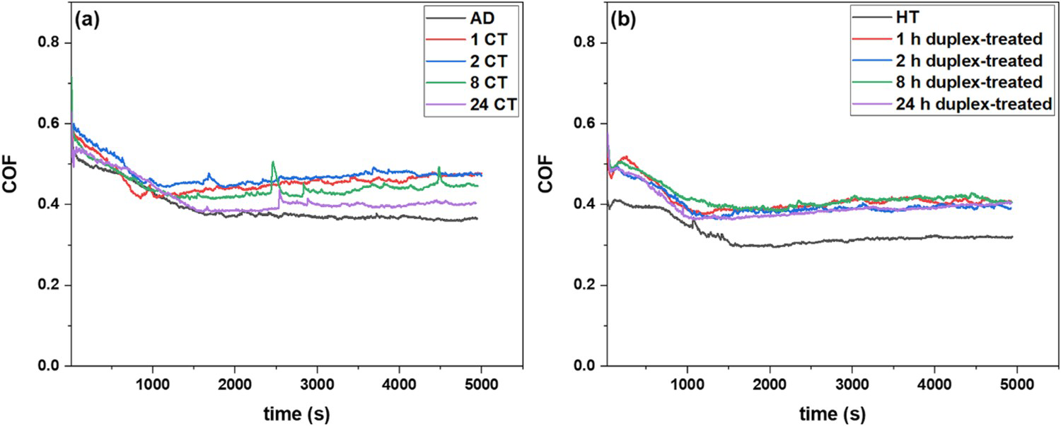
Usually, the COF depends on the mating materials, operating conditions such as dry or lubricated, and also surface conditions. The lower COF values were seen for the AD and HT coatings because of the formation of an oxide layer on the surface, and the formation of more η-carbide phases. The formed oxide layers can separate the two-mating surfaces. The lower real contact area between the mating surfaces also results in a lower COF value in the presence of the oxide layers. However, the cryogenically treated coatings show nearly similar contact areas and have nearly the same trend in the COF curve. Among cryogenically treated coatings, the cryogenically treated coatings with more treatment duration showed lower COF value due to the increase in the intensity of the η-carbide formation with time [28].
Figure 6 depicts the specific wear rate of the tested coatings. The CT coatings show significant enhancement in the wear resistance of coatings. With the cryogenic treatment duration, the wear rate was decreased which indicates that the cryogenic treatment duration affects mostly the wear rate. After heat treatment, the wear rate also decreased compared with that of the as-deposited coatings. For duplex-treated coatings, the specific wear rate was also decreased compared with that of the HT coating. Initially, for 1 and 2 h duplex-treated coatings, the wear rate decreased and after that, the wear rate started to increase for 8 and 24 h duplex-treated coatings. As-deposited coating underwent a higher rate of material loss and exhibited more wear rate as compared to all other coatings. Whereas 24 CT coatings showed better wear resistance and 2 h duplex-treated coatings also showed better wear resistance among all coatings.
Specific wear rate of the as-deposited, heat-treated coating, cryogenically treated coatings and duplex-treated (heat treatment followed by cryogenic treatment) coatings.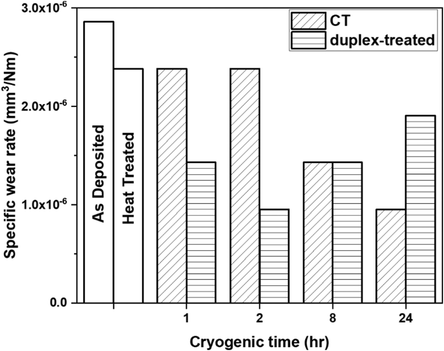
The wear behaviour of the coatings can be understood by examining the worn-out morphology. Figure 7 shows the worn-out surface of the AD and CT coatings for 1 and 24 h soaking duration and the corresponding EDS analysis. AD coatings’ worn-out morphology shows a very rough surface and cracks in the wear track. The removal of the binder matrix along with the removal of WC hard particles can be attributed to the abrasive action of the hard asperities which was dominant in AD coating. Coating spallation and delamination were also observed as severe in the case of the AD coating. W, Al, Co and O are the main elements present in the worn-out coating surface which indicates the formation of oxides during the wear test and the material from the alumina counter ball that was transferred to the coating. The 1 CT samples show a rough surface with spallation and pull-out of carbide particles due to the removal of the binder matrix. Formation of the oxide layers and again removal of the oxide layers also contributed to the wear loss of the coatings (Figure 7b). The wear debris was uniformly distributed over the worn-out surface and some of the debris has been trapped between the two mating surfaces and removed material either from one surface or both mating surfaces by acting as third-body abrasive particles. The delamination and oxidative wear were also observed as more tribo-layers were formed and removed from the surface. The alumina percentage from EDS data shows the transfer of material from alumina to the coating surface (Figure 7c). The worn-out surface of 24 CT coating was observed smooth as compared to the 1 CT sample. The cobalt matrix along with the hard particles was removed by the continuous sliding action of the counter ball due to plastic deformation. These loose hard particles act as third-body abrasive particles and remove the material by abrasion mechanism. The debris in the form of a plate-like shape uniformly spread around the surface indicates the delamination of the coatings. For AD coating, spallation and delamination resulting from the abrasive wear were observed as the main wear mechanisms. Abrasion, spallation, and tribo-layer formation and removal are the primary wear mechanisms observed for the CT coatings.
Worn-out morphology of the (a) AD coating and CT coatings for soaking duration of (b) 1 h, (c) 24 h, and the corresponding EDS analysis.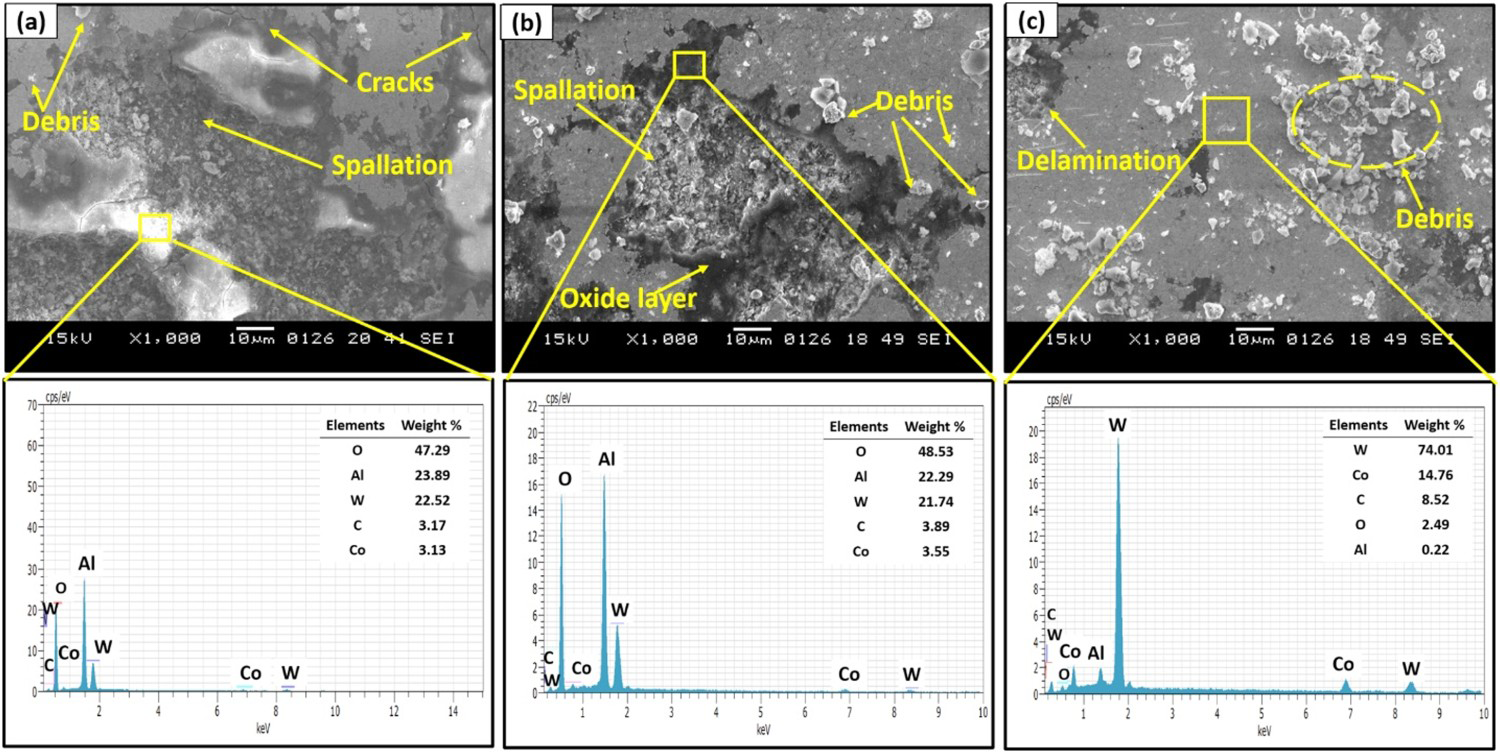
Figure 8 shows SEM images of the worn-out morphology of HT and duplex-treated coatings. The heat-treated coatings show some cracks on the surface. The coating is subjected to plastic deformation by the continuous counter ball sliding which contributes to the nucleation of the surface and subsurface cracks. Due to the continuous sliding action, these cracks and exiting porosity propagate and joins the near cracks that shear the surface and delaminate (Figure 8a). As a result, delamination was observed as more in addition to higher wear loss. Material transfer from the counter ball and the formation of oxide layers during the sliding wear is evident by EDS data. The 1 h duplex-treated worn-out morphology is smooth and the binder matrix is found to be extruded from the surface which resulted to remove the support to the WC hard particles as the binder was also pulled-out due to continuous sliding action (Figure 8b). From EDS data, it can be observed that the dark grey region has W, O and Co elements which indicate the formation of the oxide layer during the sliding wear. This oxide layer protects the surface from material loss from subsequent wear. The 24 h duplex-treated coating has a rough surface and more debris which were scattered over the worn-out surface (Figure 8c). This debris may act as third-body abrasive particles and increases the wear of the coatings. Also, some cracks can be seen from the worn-out surface attributed to the brittle cracking of η-carbides that are having more intensity at higher cryogenic treatment duration. The spalling was also observed which occurred due to the higher fatigue stress. Subsurface microcracks caused by shear stress and continual material elimination throughout wear test by hard counter balls particles trapped at the contact area are the two important causes of spalling. The formation of the oxide layers and white layers existing on the worn-out coatings due to the adhesion of alumina ball material was also confirmed by the EDS data analysis as it shows Al, O and W are the major elements in the selected region.
Worn-out morphology of the (a) heat-treated coating and duplex-treated coatings (heat treatment followed by cryogenic treatment) for soaking duration of (b) 1 h, (c) 24 h, and the corresponding EDS analysis.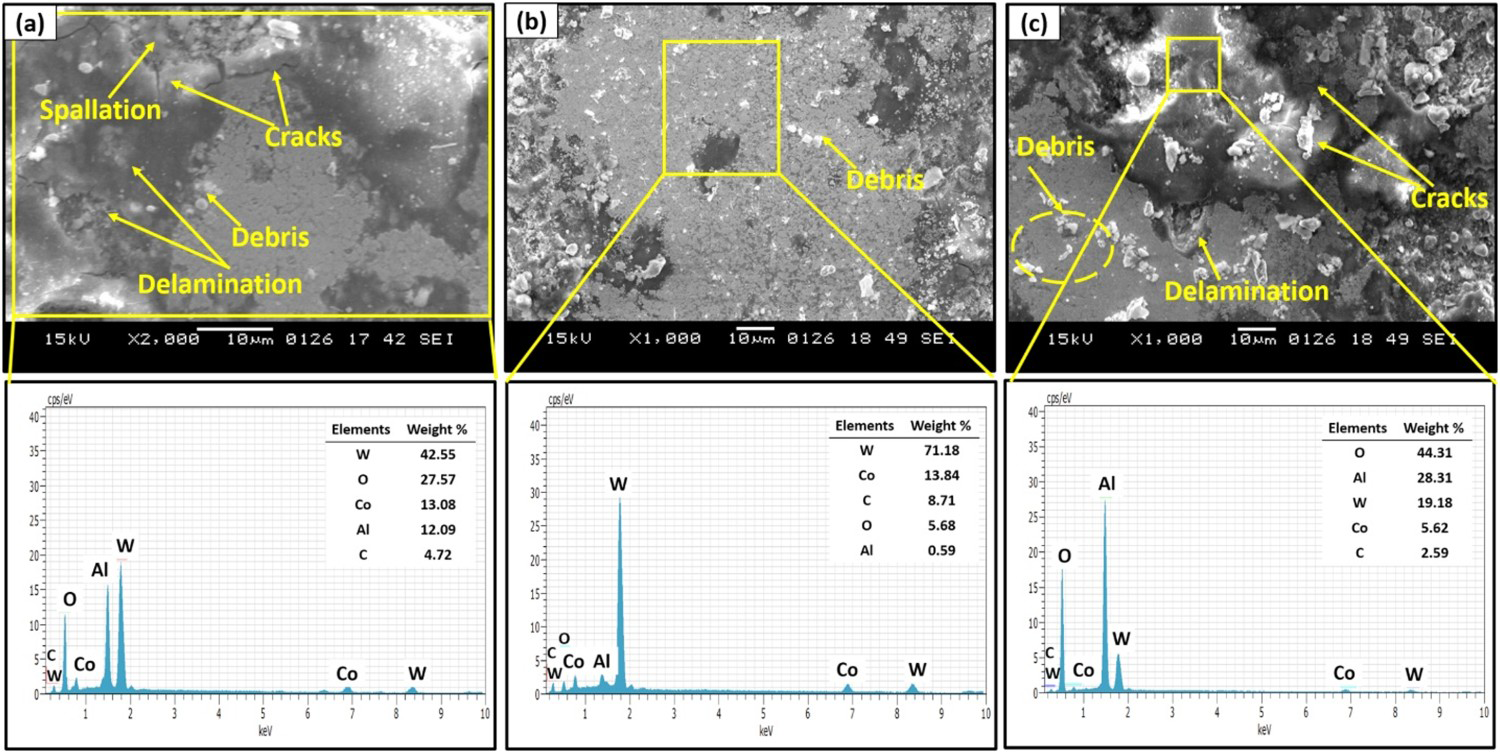
Corrosion behaviour
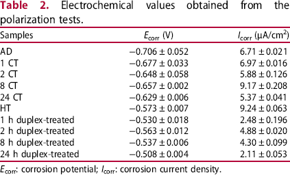
Figure 9(a) represents the polarization curves for the AD and CT coatings for different cryogenic treatment duration. It is observed that all the tested coatings exhibit similar polarization curve shapes in the NaCl solution. In the anodic corrosion, with an increase in the potential, the corrosion current density was exponentially increased for all the tested coatings as seen in Figure 9, which was due to the oxidation of Co and W [32]. The Tafel extrapolation technique is utilized to measure the Icorr and Ecorr values which are listed in Table 2. From Table 2, it can be seen that the cryogenically treated coatings when exposed to the solution, the corrosion potential is moving towards a positive value as compared to the AD coatings. With the increment in cryogenic treatment duration, the corrosion potential was also increased. The 24 CT coating has the highest corrosion potential (−0.629 V) and least corrosion current density (5.37 μA/cm2) that showed enhanced corrosion resistance of the coatings after higher cryogenic treatment duration. Figure 9(b) shows the polarization curves for HT and duplex-treated coatings. For HT and duplex-treated coatings, similar polarization curve shapes were observed. The 24 h duplex-treated coatings have the highest corrosion potential (−0.508 V) and the least corrosion current density (2.11 μA/cm2) among all the tested coatings.
Polarization curves for (a) AD coatings and CT coating, (b) HT and duplex-treated (heat treatment followed by cryogenic treatment) coatings in 3.5% NaCl. Electrochemical values obtained from the polarization tests. Ecorr: corrosion potential; Icorr: corrosion current density.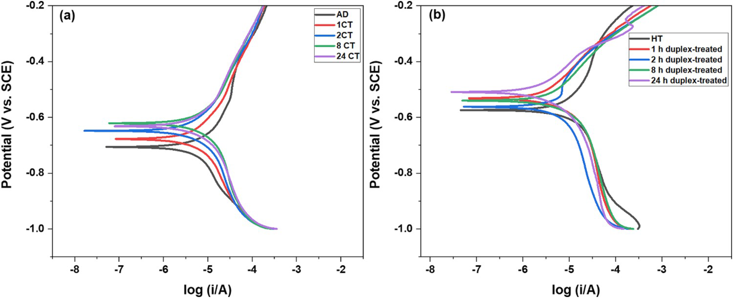
The corrosion of the metallic matrix followed by the removal of the hard phase is assumed to be the primary corrosion mechanism in WC-based materials [23,33]. Some of the reported works also found that corrosion occurred simultaneously for both the matrix as well as WC hard phase that resulted in the removal of the WC-hard particles [34]. The as-deposited coating exhibited a porous structure which acts as infiltration to the corrosion medium. When the corrosion medium infiltrates through the pores or the micro-cracks present in the coatings, galvanic corrosion is likely to occur at the interface [32]. Also, the WC material percentage is more, and the Co binder percentage is less in the deposited coatings, in such cases, considering the area ratio effect between the large WC which acts as the cathode, and the small area of Co which acts as the anode, micro-galvanic corrosion is the major corrosion mechanism for the deposited coatings [35]. Hence, the corrosion was more for the as-deposited coating. After cryogenic treatment, most of the Co matrix phases are crystalline as indicated from the XRD analysis (Figure 3), which forms the passive film in the form of an oxide layer on the cryogenically treated coatings that leads to improvement in the corrosion resistance of the coatings. The other oxide layers such as CoO and WO3 were also formed and attached to the coating surface. As a result, these corrosion products protected the corrosion surface from intense corrosion attacks [33,34]. The reduction in the porosity after heat treatment and cryogenic treatment due to the microstructure densification and cobalt distribution, the corrosion resistance of the post-treated coating was enhanced compared with that of as-deposited coatings [17,26]. It is observed that the phase composition, the binders’ chemical composition, and control over the porosity and micro-cracks are the predominant factors that control the corrosion resistance of the WC–Co coatings [32,33].
Figure 10(a) shows the Raman spectroscopy analysis of the corroded coatings. For 1 CT, the surface mainly exhibits WO3 and Co3O4 as the main constituents. The main bands of the WO3 are observed at 807–813 cm−1 which is due to the stretching vibrations of W–O and 324–332 cm−1 due to the deformation motion or bending of the O–W–O bonds [36]. Co3O4 was also observed due to the Co–O stretching vibrations at 687–691 cm−1 and 480–484 cm−1. The corroded surface also exhibited, the free WO66- octahedral elements which were observed at 879–890 cm−1 due to the stretching [37]. For 2 CT, Co3O4 was the main constituent at 480–485 cm−1 and 687–691 cm−1. The main reason for the decrease in the current density is due to the formation of Co3O4 which can be seen in Figure 9(a) that act as a barrier-type oxide. The formation of CoO was observed at 673–678 cm−1 and 467–471 cm−1 [38]. For 24 CT, the formation of Co3O4 protects the surface from corrosion as a result the corrosion current density was decreased. The broad hump was also observed at 670–710 cm−1 suggesting the occurrence of the hydrated WO3. The bands related to the bending of O–W–O and the deformation mode of O–W–O were located at 275 and 329 cm−1 respectively [39]. The formation of the WO3.
X
H2O has a layered structure due to the corner-sharing WO6 octahedral which crystallizes into different phases depending on the process parameters [40]. Figure 10(b) shows the Raman spectroscopy for the duplex-treated coating for different soaking duration. For all the coatings, a similar Raman spectrum was observed. The peak at 258 cm−1 is allotted to the WO3 [41] and also peaks at 338 cm−1 correspond to the free WO66- attributed to the stretching and bending of W–O [36,42]. The cluster of this WO66– octahedral is capable of being displayed similarly to crystalline WO3 [37]. Co3O4 was also present at 687 cm−1 which is a protective oxide layer. The main peak for the coating was found at 880 cm−1 which links to the W–O–W octahedral corner sharing bonds’ stretching vibration mode which becomes most noticeable for 24 h duplex-treated coatings [41,42].
Raman spectrums of the cryogenically treated coatings at a different soaking duration after polarization test, (a) CT coatings and (b) duplex-treated (heat treatment followed by cryogenic treatment) coatings.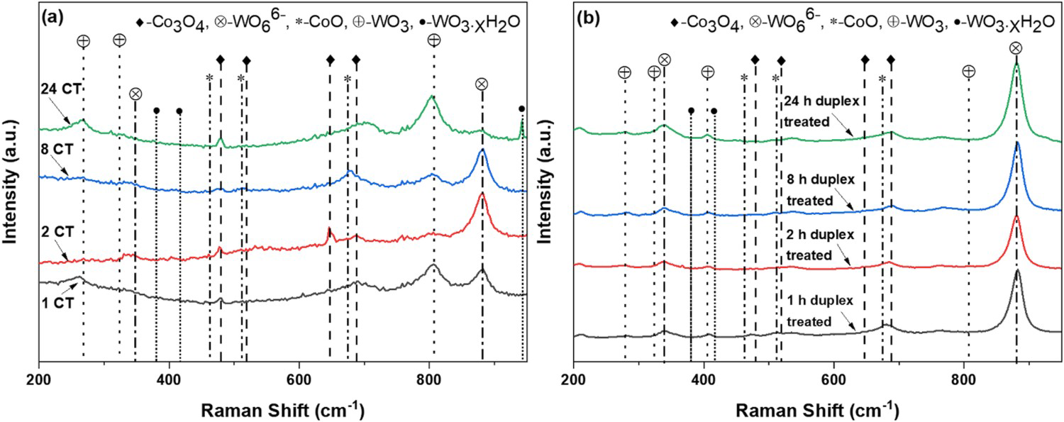
Conclusion
The WC–12Co coatings were successfully deposited on SS 410 substrates by the HVOF process. The heat treatment at 750°C for 1 h in an argon environment was carried out and further, these coatings were subjected to deep cryogenic treatment for different soaking duration. The wear resistance of the coating was increased due to the cryogenic treatment. The 24 CT coating has more wear resistance due to the densification of the cobalt matrix. The duplex-treated coatings also showed improvement after cryogenic treatment and 2 h duplex-treated coatings showed more wear resistance. The main wear mechanisms for the coatings include the pull-out of the carbide particles and spallation of the coatings due to abrasive wear, oxidative wear, and the formation and removal of the tribo-layers. The cryogenically treated coatings provided better corrosion resistance than the as-deposited coating because of the densification of the cobalt matrix leading to a decrease in the porosity of coatings and formation of the more η-carbide phases. The combination of these factors initiated the formation of the protective films, which hinder the corrosion of the binder phase. The formation of the corrosion protective film that contains WO3 and Co3O4 was observed on the corroded surface which is attributed to the decreased corrosion current density. The results demonstrate the potential of higher cryogenic treatment duration to improve the corrosion resistance of the WC–12Co coatings.
Footnotes
Disclosure statement
No potential conflict of interest was reported by the author(s).