
Abstract
The influence of silane pretreatment with five different volume ratios (100/0, 75/25, 50/50, 25/75, and 0/100) of 3-aminopropyltriethoxysilane (APTES)/tetraethylorthosilicate (TEOS) on microstructure and corrosion resistance of the hydrothermal synthesized zeolite coatings on the H13 steel substrates was investigated. The surface of the zeolite coatings on the 100/0, 75/25, and 50/50 mixture of the APTES/TEOS pretreated substrates was composed of intergrown rectangular particles. Additionally, pores were observed. A 25/75 mixture of APTES/TEOS pretreatment smoothed the edges and angles of zeolite particles with gel-like materials filled in the pores. In pure TEOS pretreatment, microcracks, and much gel-like materials were observed on the zeolite coating. The electrochemical test revealed that the zeolite coating on a 50/50 mixture of the APTES/TEOS pretreated substrate exhibited the highest corrosion resistance in 3.5 wt-% NaCl solution. This was because a 50/50 mixture of APTES/TEOS pretreatment advantageously promoted development of a dense and thick gel layer, which enhanced the intergrowth of zeolite particles.
Keywords
Introduction
H13 steel die parts can easily fail due to surface wear and corrosion from Cl−, O2-, molten aluminium, and other compounds during casting, forging, and hot extrusion. This leads to a decrease in durability and service lifetime [1–4]. To date, the most effective method to protect H13 steel is surface engineering such as thermochemical treatment [5–8], laser cladding [9,10], physical/chemical vapour deposition (PVD/CVD) [11], and thermal spraying [12], of which thermochemical treatment can form a compound or diffusion layer with high hardness to improve wear resistance [5,6]. However, the corrosion resistance could not be improved significantly [7,8]. Additionally, the high temperatures involved in its processes can cause size changes and shape distortion in the parts. For a die/mold with high precision requirement, the high-temperature process should be avoided. Whereas other surface treatments, their limitations also are apparent, for example, the unavoidable pores formed during laser cladding can negatively impact corrosion resistance [9,10]; the operation cost of physical/chemical vapour deposition (PVD/CVD) is high [11]. Consequently, the demand for alternative treatment is increasing.
A zeolite coating can potentially protect die/mold steel owing to its good crystallinity, corrosion, and wear resistance [13–18]. Chow et al. [17] reported that a ZSM-5 zeolite coating on aircraft-grade 4130 steel exhibited higher wear resistance than that imparted by electroplated chromium and cadmium coatings via nano-scratch test. This is attributed to the low modulus and high hardness of zeolite particles. Mitra et al. [19] reported that MTW (ZSM (Zeolite Socony Mobil)−12, BEA (zeolite beta), and MFI (Mobil Five)) zeolite coatings prepared by one-step hydrothermal synthesis on 304 stainless steel plates were continuous and dense; therefore, they could impart higher corrosion resistance. A zeolite coating can be prepared on metal substrate by methods such as dry-gel conversion [20] and hydrothermal synthesis [21,22]. Among them, hydrothermal synthesis is tremendously suitable for die/mold steel because of its low-temperature process (≤200°C), which can advantageously reduce the deformation and distortion of die/mold parts [23].
Because of the high Cr content in H13 steel, it is challenging to hydroxylate its surface. This leads to a weak interaction between the precursor and H13 steel substrate during hydrothermal synthesis [24,25], and thus hinders the growth of zeolite coating on the H13 steel surface. Surface functionalization using different silane coupling groups (e.g. –Cl, –NH2, –OH) significantly eliminates the problem of reactivity heterogeneity from region to region on metal substrate, and facilitates the deposition of a gel layer and promotes the nucleation of zeolite particles on the substrate, while also improving the compatibility between the substrate surface and zeolite coating [26–30]. In view of this, silane pretreatment is typically utilized to increase the gas separation performance of zeolite coatings on steel substrates. Chau et al. [26] reported that the pretreatment of a 3-mercaptopropyltrimethoxysilane surfactant enhanced the zeolite coating quality. Huang et al. [27] reported that a 3-chloropropyltrimethoxysilane (CPTES) pretreatment improved the microstructure and gas separation performance of a zeolite coating on porous stainless steel. Martinez et al. [28] prepared a NaA zeolite coating on pre-calcined and then 3-aminopropyltriethoxysilane (APTES)-treated 316 L stainless steel, and the zeolite coating presented an improved crystal intergrowth and separation performance. Single silane pretreatment has been commonly conducted to enhance the separation performance of a zeolite coating on metal substrate; however, the influence of mixed silane pretreatment with higher flexibility on the microstructure and corrosion resistance remains unknown.
In this work, with the aim to improve the corrosion resistance of the zeolite coating and expand the application on the die processing industries, the mixture solution of 3-aminopropyltriethoxysilane (APTES)/tetraethylorthosilicate (TEOS) with different volume ratios was used to pretreat H13 steel, and study its influence on the microstructure and corrosion resistance of the zeolite coating prepared by one-step hydrothermal synthesis.
Materials and methods
Substrate preparation
H13 steel was selected as the substrate, and its chemical composition was as follows (wt-%): C 0.32-0.45, Si 0.80-1.20, Cr 4.75-5.50, Mn 0.20-0.50, Mo 1.10-1.75, Fe in balance. The substrate had a size of 20 × 15 × 2 mm3, and a 2 mm diameter hole was drilled on the edge. Prior to pretreatment, the substrates underwent a polishing process using 80, 320, and 800 # sandpaper, followed by ultrasonic cleaning in an alcohol bath.
The chemical reagents used in the experiment were as follows: APTES (C9H23NO3Si, ≥98%) and TEOS (C8H20O4Si, ≥98%) were obtained from Macklin Chemical Reagent; tetrapropyl ammonium hydroxide (TPAOH, C12H28NOH, ≥99%) was purchased from Jiuding Chemical Reagent; ethyl alcohol (C2H5OH, ≥99.7%) was purchased from Hunan Hui Hong Reagent Co., Ltd.; sodium hydroxide (NaOH, analytically pure) and sodium chloride (NaCl, analytically pure) were obtained from Xilong Chemical Co., Ltd.; distilled water was prepared in the laboratory.
Silane pretreatment
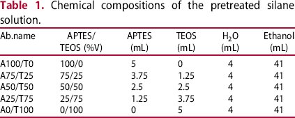
Chemical compositions of the pretreated silane solution.
Zeolite coating preparation
The zeolite coating was synthesized on the various volume ratios of APTES/TEOS pretreated H13 steel substrates by hydrothermal synthesis. The solution was prepared using the following molar ratio: TPAOH:NaOH:TEOS:H2O = 0.16:0.64:1:92, and stirred at ambient temperature (10–15°C) for 5–6 h. In this study, the chemical formula of the zeolite was (SiO2)6 H2O, i.e. silicate-1 zeolite coating. The pretreated substrates were placed vertically on the Teflon-lined stainless steel autoclave using an iron wire, and then placed at 180°C for 20 h. The obtained samples were ultrasonically cleaned in an alcohol bath, followed by blow-drying. The zeolite coatings synthesized on the H13 steel substrates pretreated by 100/0, 75/25, 50/50, 25/75, and 0/100 (in volume ratio (%)) mixture of the APTES/TEOS were named as the ZC-0, ZC-25, ZC-50, ZC-75, and ZC-100 coatings, respectively.
Characterization
The functional group information of the substrate surface after various volume ratios of APTES/TEOS pretreatment was analysed by a Fourier-transform infrared (FTIR, Thermo Fisher Scientific Is-50) spectrometer, during which the spectra were recorded in the wavelength of 500–4000 cm−1 with 2 cm−1 resolution. The morphologies and elemental compositions of the zeolite-coated samples were investigated by scanning electron microscope (SEM, EVOMA10) equipped with an energy dispersive spectrometer (EDS), before which the cross-sectional samples were polished with 320, 800, and 1500 # sandpaper and diamond polishing paste. The phase compositions of the zeolite-coated samples were determined by X-ray diffraction (XRD, D/max 2550 VB, Cu Kα radiation), operated with a scanning 2 θ range of 5–50° and the scan speed of 4°/min.
Potentiodynamic polarization curves and electrochemical impedance spectroscopy (EIS) tests were used to analyse the corrosion resistance of H13 steel and the zeolite-coated samples, before which the surface of the samples were sealed by a mixture of rosin and paraffin except for a 1 cm2 exposed area. Both were carried out in 3.5 wt-% NaCl solution at ambient temperature (10∼15°C) using CHI660 electrochemical workstation, wherein the samples served as the working electrode, whereas the saturated calomel electrode (SCE) and platinum plate were used as the reference and counter electrode, respectively. The voltage range and scanning rate of polarization curves were from −1.6 to 0 V [25] and 0.002 V/s, respectively. The EIS tests were conducted at the open circuit potential (OCP), and the frequency was from 100 000–0.01 Hz. In order to decrease the error, the reference electrode should be close to the working electrode as possible. Additionally, the samples with zeolite coatings were immersed into 3.5 wt-% NaCl solution for 30 min to ensure the surface stability prior to test; following the open circuit potential curve (OCP) was tested until it was stable.
At ambient temperature (10∼15°C), the samples with a 1 cm2 exposed area were immersed into 3.5 wt-% NaCl solution for 1680 h, during which its surface variations were recorded via a digital camera. Prior to the immersion test, the H13 steel substrates were polished with 80, 320, and 800 # sandpaper and ultrasonically cleaned in an alcohol bath.
Results and discussion
Characteristics of zeolite-coated samples
Surface analysis
Figure 1 shows the surface morphologies of ZC-0, ZC-25, ZC-50, ZC-75, and ZC-100 coatings on the H13 steel substrate. As shown in Figure 1(a), the ZC-0 coating comprises intergrown and rectangular zeolite particles with different sizes and orientations. Several pores also appear on the surface, which are caused by incomplete intergrowth between adjacent zeolite particles. Although the particles of the ZC-25 coating in Figure 1(b) are smaller than that in Figure 1(a), the quantity of pores increases. As for ZC-50 coating in Figure 1(c), it shows a well-intergrown structure between adjacent zeolite particles. Consequently, few pores are presented on the surface. Further increasing the TEOS volume ratio (APTES/TEOS = 25/75), the edges and corners of zeolite particles on the ZC-75 coating become much smoother (Figure 1(d)). By the insert in Figure 1(d), gel-like materials can be observed. When applying pure TEOS pretreatment (APTES/TEOS = 0/100), as shown in Figure 1(e), several microcracks are presented, and the pores vanish. The primary reason for the surface cracks was due to thermal stress caused by a significant mismatch of thermal expansion coefficients between gel-like materials and zeolite particles.
Surface morphologies of (a) ZC-0, (b) ZC-25, (c) ZC-50, (d) ZC-75, and (e) ZC-100 coatings.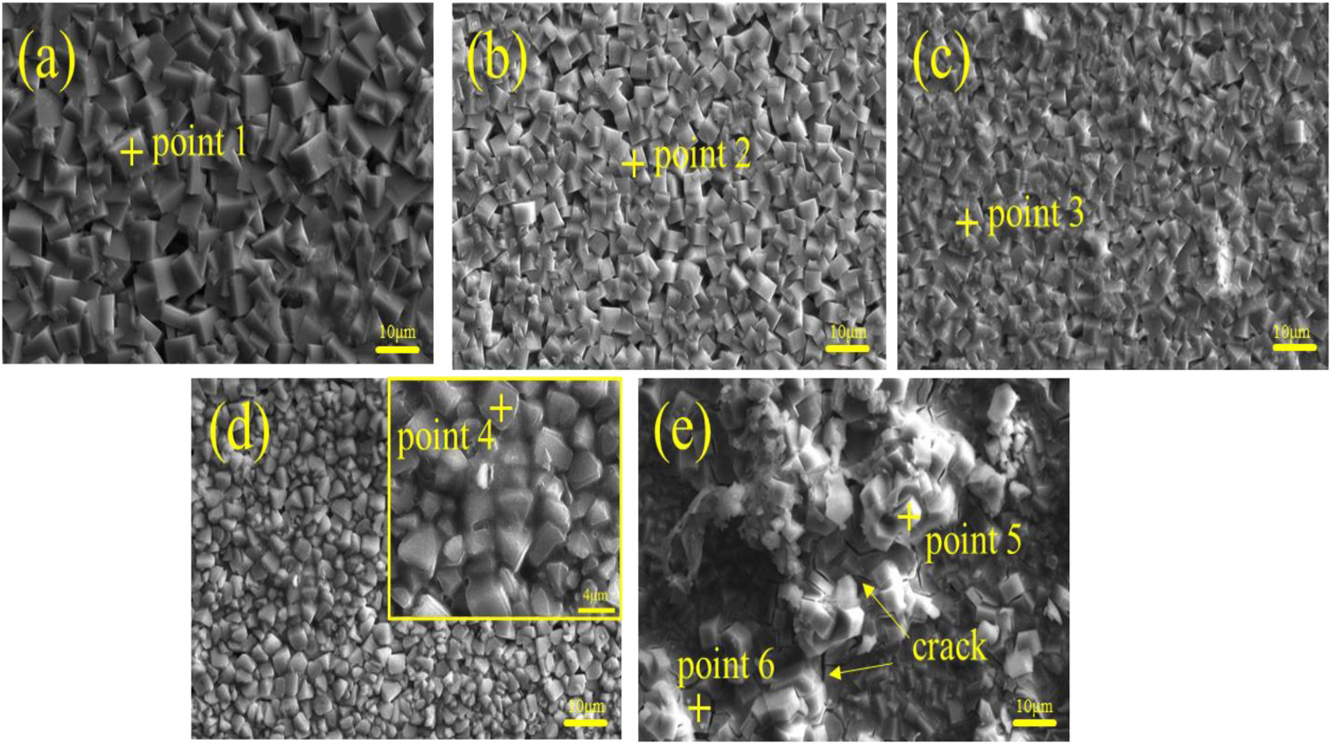
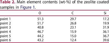
Table 2 shows the chemical element content of points 1–6 in Figure 1. The Si and O were the primary elements of zeolite framework. The presence of C components was ascribed to the structure-directing template (SDT) of TPAOH in the zeolite framework. As shown in Table 2, the C content of point 5 at zeolite particles is lower than that of point 6 at gel-like materials. This was because the gel-like materials were formed by the condensation of the silanol groups (≡Si-OH), obtained from TEOS hydrolysis [18].
Cross-sectional analysis
Figure 2 shows the cross-sectional morphologies and thickness variations of ZC-0, ZC-25, ZC-50, ZC-75, and ZC-100 coatings on the H13 steel substrates. As shown in Figure 2(a–e), micropores with different sizes were distributed within the zeolite coating, wherein the ZC-50 coating (Figure 2(c)) has the least micropores. At the same time, there are no apparent separation or microcracks at the interface between the H13 steel substrate and zeolite coatings. Notably, the ZC-25 coating (Figure 2(b)) shows a discontinuous characteristic, which is due to the weakly intergrown zeolite particles exfoliating during the mechanical polishing process. The thickness of ZC-0, ZC-25, ZC-50, ZC-75, and ZC-100 coatings is 15.35 ± 0.68, 7.6 ± 0.95, 6.32 ± 0.41, 7.05 ± 0.58, and 9.68 ± 0.78 μm, respectively, displaying a tendency of first decreasing and then increasing with increased TEOS content (Figure 2(f)).
Cross-sectional morphologies of (a) ZC-0, (b) ZC-25, (c) ZC-50, (d) ZC-75, and (e) ZC-100 coatings; (f) the thickness variation of the five zeolite coatings.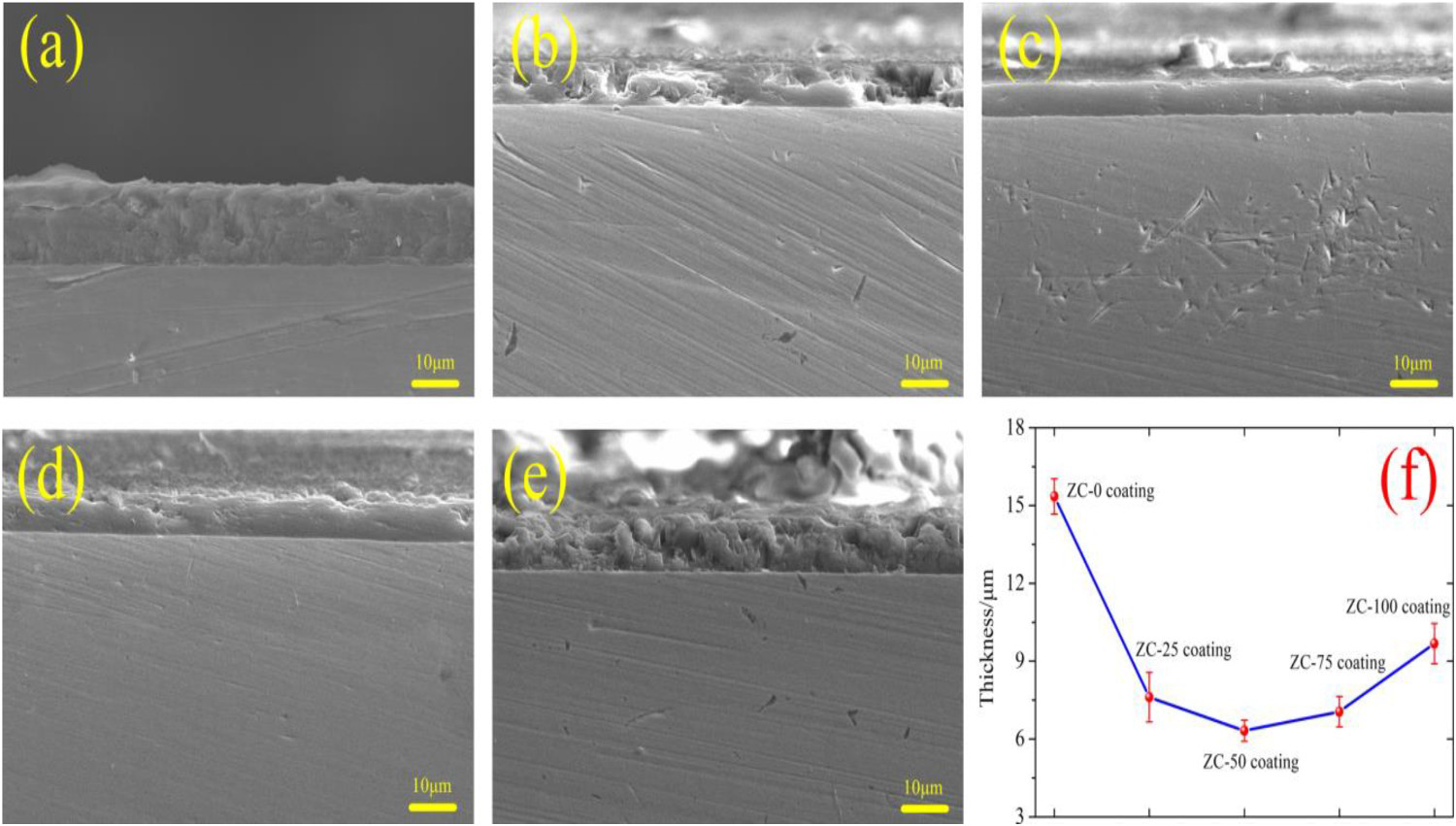
Phases analysis
Figure 3 shows the XRD patterns of the zeolite-coated samples. A strong martensite (α′-Fe) peak at 44.66° of 2 θ (PDF#65-4899) was observed on zeolite-coated samples due to the penetration of X-ray. At the same time, the peaks presentation of ZSM-5 zeolite (PDF#44-0009) indicated that the various volume ratios of APTES/TEOS pretreatment did not change the phase of the zeolite coating.
XRD diffraction patterns of the five zeolite-coated samples.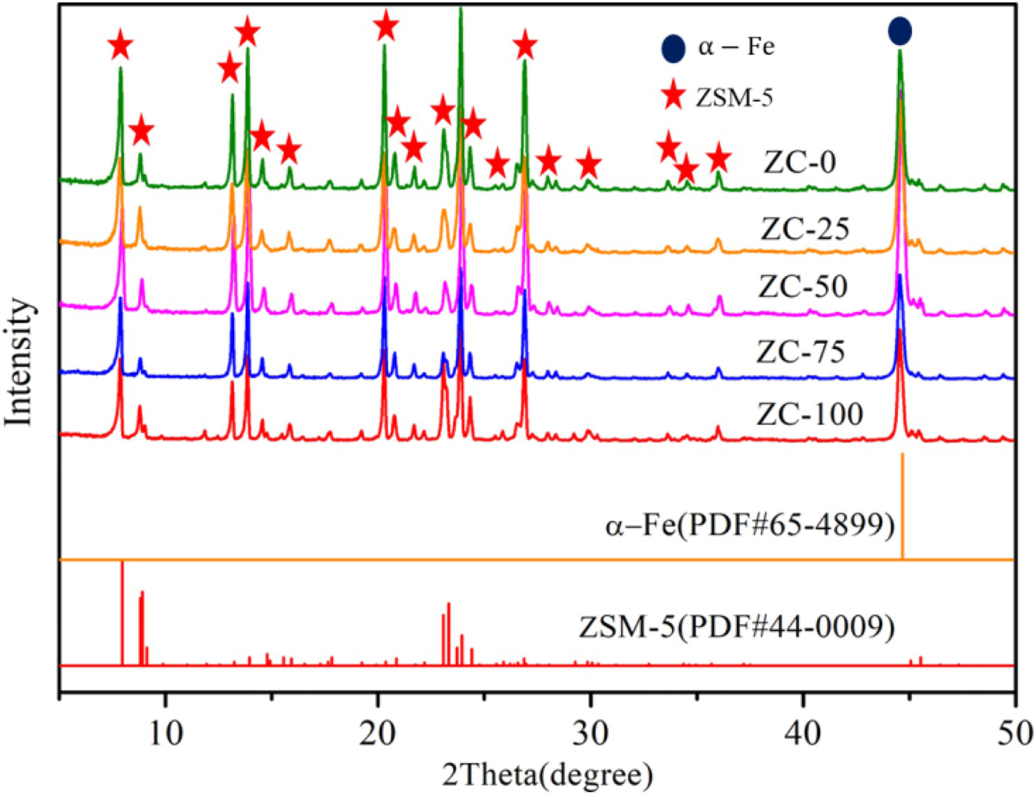
Influence of silane pretreatment on zeolite coatings
Figure 4 shows the FTIR spectra of the various volume ratios of APTES/TEOS pretreated H13 steel substrates. The weak peaks around 2850 and 2927 cm−1 can be ascribed to -CH of the ≡Si-(CH2)3-NH2 in APTES, or incompletely hydrolysed ≡SiOC2H5 in TEOS [31]. For APTES-pretreated specimen, the significant peak around 1020 cm−1 corresponds to the stretching of Si-O-Si in the silane film [30,32,33]. The strong peaks at 1472 and 1556 cm−1 are assigned to the vibration of –NH2 groups [31,34], whereas that at 1630 cm−1 is related to the silanol groups (≡Si-OH). For the mixed APTES- and TEOS- pretreated specimens, the Si-O-Si peak around 1020 cm−1 gradually decreases with the increased volume ratio of TEOS. At the same time, the Si-O-Si peak of the 50/50 mixture of APTES/TEOS pretreated substrate is much wider, suggesting better cross-linking in the formed film. For pure-TEOS-pretreated specimen, a strong peak corresponding to hydrogen bonded –OH groups at 3209 cm−1, and a strong peak corresponding to –CH at 1440 cm−1 can be observed.
FTIR spectra of the H13 steel substrates at various volume ratios after APTES and TEOS pretreatment: (a) 500–2000 cm−1 and, (b) 2500–4000 cm−1.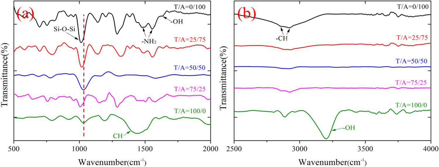
In summary, during the aging process under neutral condition, the alkoxy groups on APTES easily hydrolysed to silanol groups (≡Si-OH) via the reaction equation of (1). In contrast, TEOS exhibited weaker hydrolysis ability, resulting in only partial conversion of alkoxy groups to silanol groups (≡Si-OH). Subsequently, when the H13 steel substrate underwent the silane pretreatment and curing process, a thin silane film was formed by intermolecular condensation among the silanol groups (≡Si-OH), and between the silanol groups (≡Si-OH) and the hydroxyl groups related to element Fe on the substrate via the reaction equations of (2)–(3) [29,31, 35–37]. As for element Cr, there may be a specific interaction between the amino –NH2 groups on the hydrolysed APTES and oxide of Cr on the substrate [37]. Based on above analysis, the schematic structures of the films formed on the substrates by solutions of APTES, a 50/50 mixture of APTES/TEOS, and TEOS pretreated substrate are shown in Figure 5.
Bonding methods of the silane layer with the H13 steel substrate.


where the ≡Si-OC2H5 represents the APTES or TEOS.
Formation mechanism of zeolite coatings
Main element contents (wt-%) of the zeolite coated samples in Figure 1.
Corrosion resistance of zeolite-coated samples
Potential polarization curve
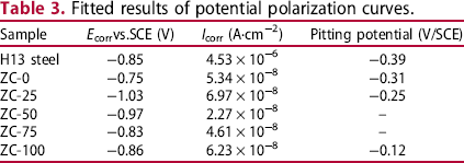
Figure 6 shows the potential polarization curves of the H13 steel substrate and zeolite-coated samples. The corresponding fitted results are listed in Table 3. As shown in Figure 6 and Table 3, the Icorr of six samples are arranged as follows: H13 steel substrate (4.53 × 10⁻⁶ A·cm−2) > ZC-25 coating (6.97 × 10⁻⁸ A·cm−2) > ZC-100 coating (6.23 × 10⁻⁸ A·cm−2) > ZC-0 coating (5.34 × 10⁻⁸ A·cm−2) > ZC-75 coating (4.61 × 10⁻⁸ A·cm−2) > ZC-50 coating (2.27 × 10⁻⁸ A·cm−2), from which it is discovered that the Icorr values of the zeolite-coated samples are about two orders of magnitude lower than that of the H13 steel substrate. This indicates that the zeolite coating has excellent corrosion resistance. Additionally, a pitting potential was present on the H13 steel substrate, ZC-0, ZC-25, and ZC-100 coatings. This can be ascribed to the defects on the zeolite particles layer, like pores and microcracks (as shown in Figures 1(a, c, and d)), allowed the electrolyte solution to penetrate and reach the gel layer, leading the gel layer beneath this portion first degraded to form defects [31].
Potential polarization curves of the H13 steel substrate and the zeolite-coated samples in 3.5 wt-% NaCl solution. Fitted results of potential polarization curves.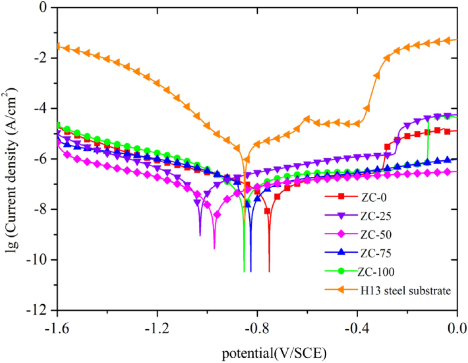
Electrochemical impedance spectroscopy tests
Figure 7 shows the Bode curves of the H13 steel substrate and zeolite-coated samples. As shown in Figure 7(a), the low-frequency impedance modulus of the H13 steel substrate is 1.05 × 10³ Ω·cm2, indicating its poor corrosion resistance. For the zeolite-coated samples, the Bode curves in Figure 7(b–f) show two-time constants, separately at high (∼104.5 Hz) and low frequency (∼100 Hz). The time constant at high frequency was attributed to the outside barrier effect of the zeolite particles layer, while that at low frequency was related to the interfacial gel layer. The impedance modulus at 0.01 Hz (│Z│0.01) reduces with the increased immersion time, indicating the gradual failure to the coating. The values of │Z│0.01 in Figure 7(b–f) are 2.41 × 10⁵, 5.34 × 10⁵, 1.01 × 10⁶, 1.18 × 10⁶, and 5.06 × 10⁵ Ω·cm2 at 1 h, and decrease to 2.36 × 10⁴, 1.01 × 10⁴, 2.95 × 10⁵, 1.03 × 10⁵, and 3.40 × 10⁴ Ω·cm2 after 600 h of immersion, respectively.
Bode curves of (a) H13 steel substrate, (b) ZC-0, (c) ZC-25, (d) ZC-50, (e) ZC-75, and (f) ZC-100 coatings in 3.5 wt-% NaCl solution.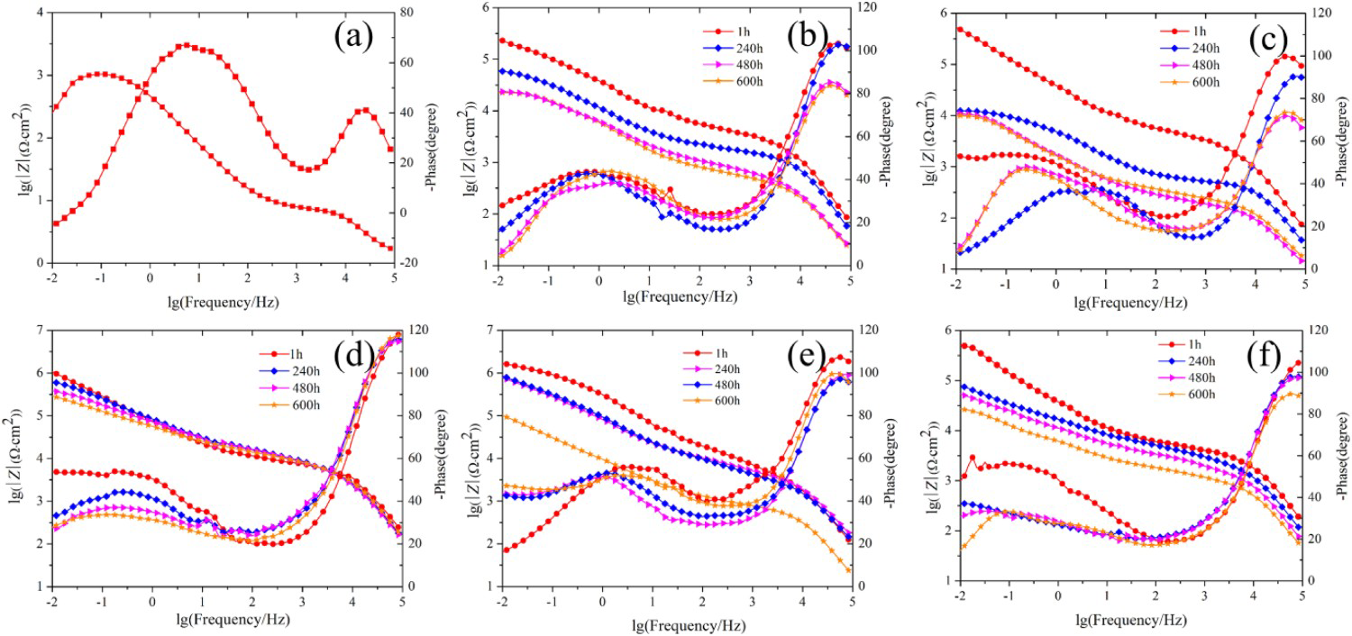
The equivalent circuit model [25] in Figure 8 was used to fit the electrochemical impedance data, where the Rs represented the solution resistance; QPEz and Rz represented the constant phase element and resistance caused by the zeolite particles layer; Ws represented the impedance caused by the diffusion behaviour; and QPEg and Rg represented the constant phase element and resistance caused by the gel layer, respectively.
Equivalent circuit model used to fit the EIS data of the five zeolite coatings.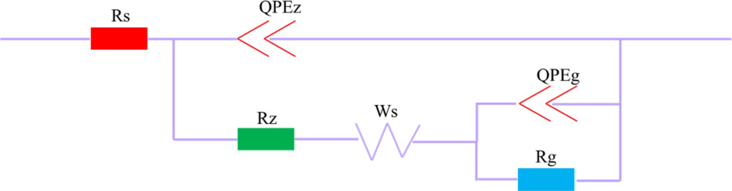
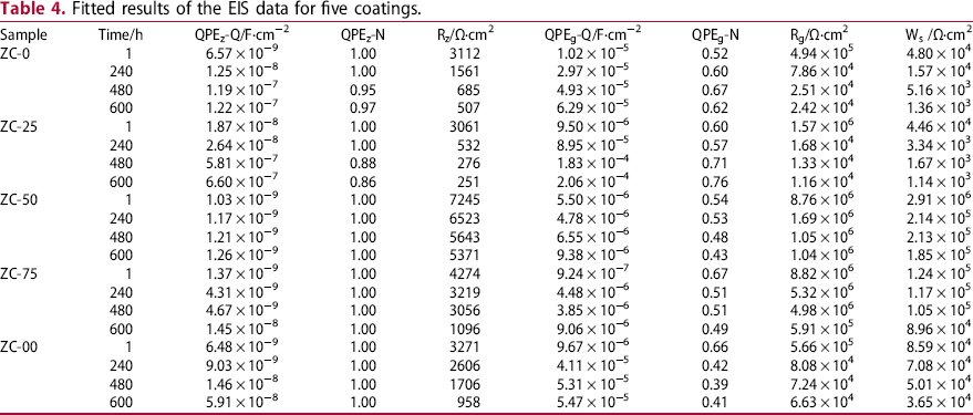
Fitted results of the EIS data for five coatings.
Immersion test
Figure 9 shows the surface variations of the H13 steel substrate and zeolite-coated samples in 3.5 wt-% NaCl solution at ambient temperature (10∼15°C). For the H13 steel substrate, its surface was severely corroded and covered by rust at 600 h. While for the zeolite-coated samples, the surface of the samples with the ZC-0, ZC-25, ZC-75, and ZC-100 coatings got yellow, and several corrosion pits were also observed at 1680 h. However, the surface of the ZC-50 coating maintained its original lustre, and few corrosion pits were observed at 1680 h.
Digital photos of the H13 steel substrate and zeolite-coated samples after immersing in 3.5 wt-% NaCl solution.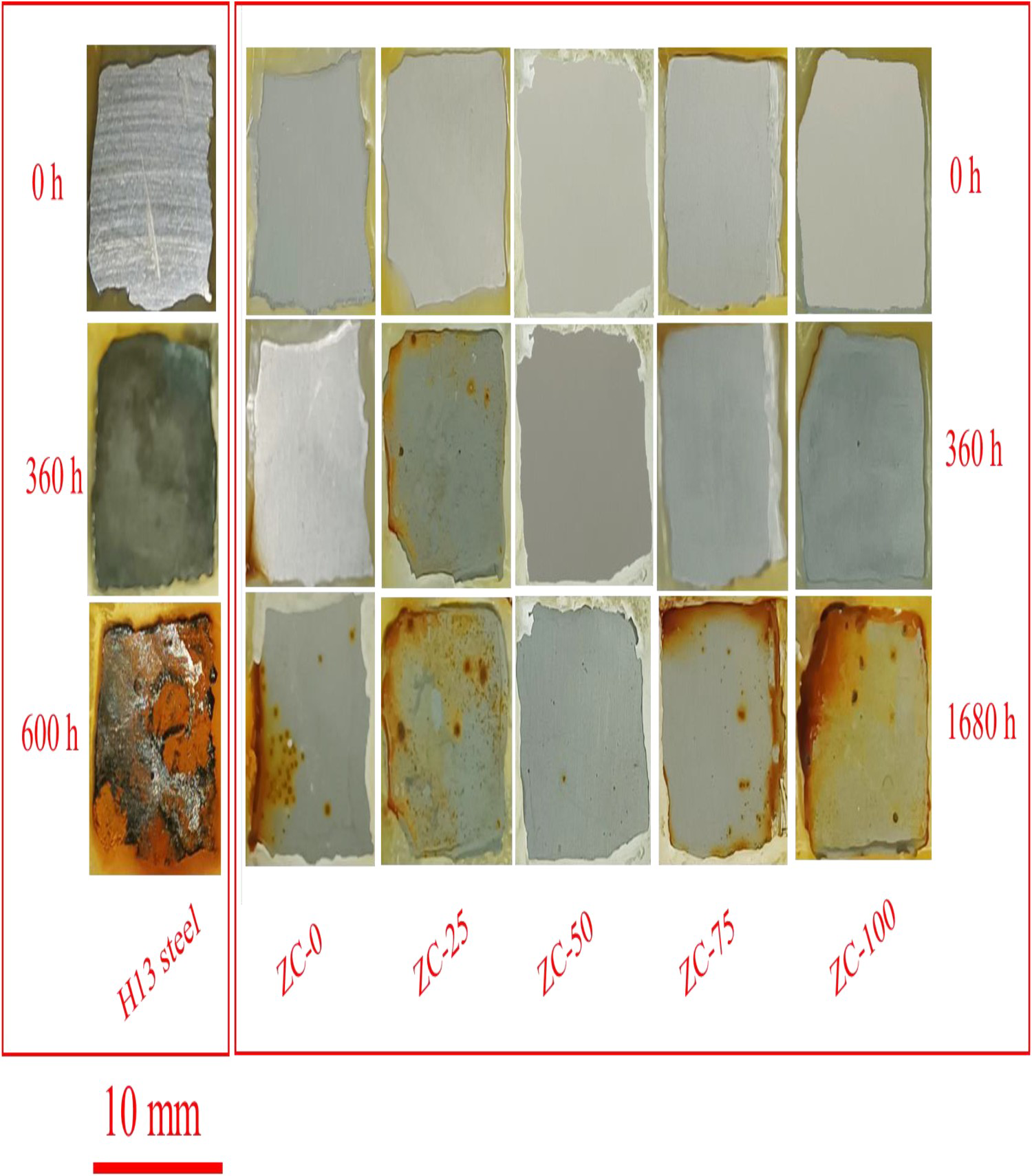
The electrochemical and saline immersion tests demonstrated that the zeolite coating greatly enhanced the corrosion resistance of the H13 steel substrate. The reason for this is, on one hand, the zeolite particle is composed of [SiO4]- unit, which has stable chemical property and thus presents high resistance to corrosion media [18,25]. On the other hand, the gel layer between the zeolite particles and the H13 steel substrate can further prevent the corrosion media from penetrating into the substrate, reducing the corrosion rate [18, 25]. Also, it was concluded that the ZC-50 coating had the best corrosion resistance for long time. This was possibly attributed to that the 50/50 mixture of APTES/TEOS pretreatment enabled the formation of a dense and thick interfacial gel layer, which significantly helped to increase the intergrowth degree between adjacent zeolite particles. Consequently, the corrosion media was much more difficult to penetrate through the zeolite coating to corrode the H13 steel substrate.
Conclusions
A zeolite coating was synthesized on the H13 steel substrate pretreated by 100/0, 75/25, 50/50, 25/75, and 0/100 (in volume ratio (%)) mixture of the APTES/TEOS. SEM images showed the zeolite coating on the 100/0, 75/25, and 50/50 mixture of the APTES/TEOS- pretreated substrate was composed of incompletely intergrown particles. Additionally, the 50/50 mixture of APTES/TEOS pretreatment led to the formation of zeolite coating with least porosity. On application of the 25/75 mixture of APTES/TEOS pretreatment, the adjacent particles of the zeolite coating lacked sufficient intergrowth, and their edge and angle became smoother. Additionally, the pores between adjacent particles were filled with gel-like materials. Several cracks caused by the thermal stress between the zeolite particles and gel-like materials were observed on the pure-TEOS-pretreated substrate. The electrochemical and immersion tests showed the zeolite coating, synthesized on the 50/50 mixture of the APTES/TEOS-pretreated substrate, had the best corrosion resistance in 3.5 wt-% NaCl solution. It had the lowest value of Icorr and the highest value of │Z│0.01 for a long time.
Footnotes
Acknowledgement
This work was supported by the National Key Research and Development Program of China (grant 2017YFB0306301).
Disclosure statement
No potential conflict of interest was reported by the author(s).