
Abstract
It has a strict demand for the transverse thickness difference of silicon steel. To reduce the transverse thickness difference of the cold rolled strip, it must reduce the crown and the wedge of the hot rolled strip. 7-Stands continuously variable crown (CVC) hot rolling mills are conventionally applied to roll silicon steel. However, the CVC rolling mills have many defects to roll silicon steel as a result of the strict demands for the crown and the wedge and the characteristics of the CVC rolling mill. The large concave roll (LCR) technology was puts forward to solve that problem. The LCR technology includes the design of the roll contour and the roll free shifting strategies. The results of simulations and experiments show that the LCR technology can not only ensure the crown target of silicon steel, but also enlarge the coil quantity in a rolling schedule and improve the hot rolled strip edge-drop in the late of rolling schedule. This technology provides guidance for the crown control of the hot rolled silicon steel.
Introduction
Non-oriented silicon steel is widely used in the manufacturing of the motor that strips are mainly stacked in layers to produce motor rotors and stators. Reducing the gap between stacks as small as possible is advantageous for improving the efficiency of motors and reducing energy loss. Therefore, the ideal shape of the silicon steel strip is rectangular, keeping the minimum transverse thickness difference of strips. The downstream users of silicon steel have increasingly strict demands for the transverse thickness difference with the continuous improvement of industry technology. It continuously impels iron and steel enterprises to carry out technical research for reducing the transverse thickness difference of the cold rolled silicon steel. Many new technologies of controlling the cross-section shape are emerging continuously. They included the continuously variable crown (CVC) rolling mill technology, 1,2 the pair crossed 3,4 rolling mill technology, the work roll shifting (K-WRS) technology, 5 the taper work roll shifting (T-WRS) 6 technology, the taper work roll shifting and crossing (T-WRS&C) 7,8 technology and the edge variable crown 9 work roll technology. The main technologies for improving the strip cross-section shape during the cold rolling process is to reduce the strip edge-drop, but the control ability of the cold rolling is limited. Moreover, the control of both the strip transverse thickness difference and the strip flatness have coupling natures. The technology of controlling the strip edge-drop usually induces flatness defects, edge cracks, strip broken and other unstable factors for cold rolling.
The cross-section shape of the hot rolled strip has a significant effect on the control of the transverse thickness difference during cold rolling. If the incoming strip of cold rolling has a wedge, the reductions of both sides of strip are kept the same by adjusting levelling during the cold rolling so that the actual flatness can approach the target of the closed loop control system. It is almost impossible to eliminate the wedge of the hot rolled strip during cold rolling. Li et al. 10 pointed out that, the greater the crown and the wedge of the hot rolled silicon steel strip, the more serious the edge-drop of the cold rolled strip. Zhang and Liu 11 found that the crown reduction of the hot rolled strip can effectively decrease the transverse thickness difference of the silicon steel in cold rolling. The central crown of the cold rolling strip is mainly affected by the crown of the incoming strip. In addition, the crown and the edge-drop of the hot rolled strip also affect the flatness control in cold rolling, which weakens the ability of controlling the edge-drop during cold rolling process. It reaches broad consensus on that the cross-section shape of the hot rolled strip must be controlled to decrease the transverse thickness difference of the silicon steel during cold rolling. Ou et al. 12 measured the work roll (WR) wear and contrasted the strip cross-section shape in the whole rolling process. It pointed out that the key to reduce the transverse thickness difference of cold rolled non-oriented silicon steel is hot rolling. The main reason of the large crown in hot rolling is that the serious wear of the WR will increase the strip edge-drop.
Owing to the increasing demands for the cross-section shape of the hot rolled strip, many new technologies for the cross-section shape control in hot rolling are emerging continuously. For the purpose to control the continuously increasing wear of the WR, Kitahama et al. 13 developed the working roll shifting (K-WRS) mill and applied in hot rolling. Zhang et al. 14 proposed asymmetric self-compensation work roll (ASR) technology to achieve the free rolling. Wang et al. 15 proposed rectangular section control technology for silicon steel. High performance variable crown work roll contour and variable crown back-up roll contour were applied in hot rolling to improve the strip crown. And limited shifting technology for schedule-free rolling was applied to the downstream stands of hot rolling. Aiming at solving the effects of the serious wear of the WR in the downstream stands in the hot rolling of silicon steel, Cao et al. 16,17 applied ASR technology and the WR shifting and bending strategy to achieve the control of the silicon steel crown of 1700 hot rolling mill in the Wuhan Iron and Steel Company Limited. In order to enhance the ability of controlling the crown and the edge-drop for silicon steel, container plate and high strength steel, He et al. 18 developed the asymmetrical Ansteel strip product work roll and applied it in Ansteel 1700 mill downstream stands. It well realised both the WR uniform wear and the strip shape control.
The optimal crown and wedge of the hot rolled strip are required for the sake of reducing the transverse thickness difference of the cold rolled silicon steel. However, the crown control and the wedge control are in the contradiction relationship. The small target crown lead to poor rolling stability, which prone to make the strip wedge more serious. Silicon steel is mostly rolled by the CVC mills in hot rolling. The crown control field of the CVC roll is large, which can satisfy the controlling demands of the strip crown of different specifications. It is especially suitable for applying in the upstream mills of hot rolling. Downstream stands of the hot rolling mill mainly control strip flatness, and do not need the strong control ability for the strip crown. Actually, the shifting stroke of the CVC WR in the downstream is always small. It does not give full play to the strong adjustment ability for the strip crown. On the contrary, the small shifting stroke of the CVC WR results in that the ‘U’ shape wear become serious in the downstream, which will aggravate the strip edge-drop gradually with the rolling schedule increasing. The schedule-free technology of hot rolling is gradually becoming more and more popular. The serious ‘U’ shape groove wear of the WR in the downstream mill is the most important factor to limit the schedule-free hot rolling.
19
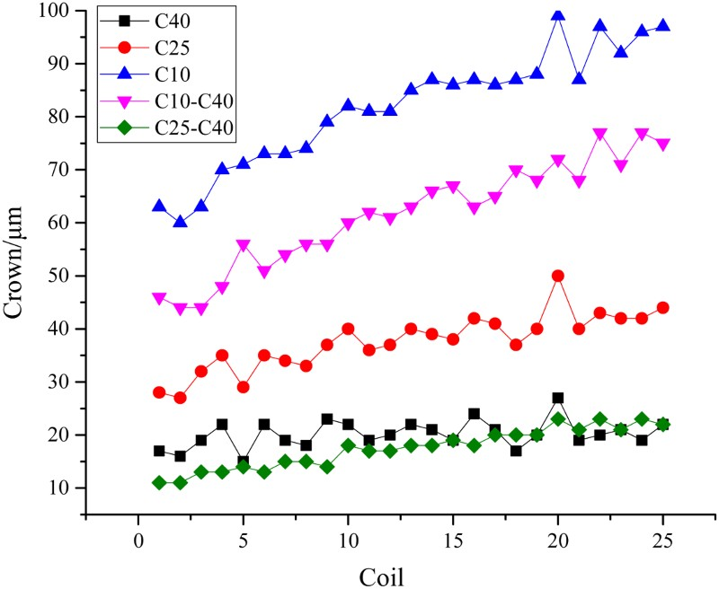
The rolling force of silicon steel is much greater than conventional steels, and specification range vary little, and the ‘U’ shape wear of the WR becomes serious in the late of rolling schedule. Figure 1 is the WR wear distribution of the 7th finishing stand (F7) of the CVC rolling mill after rolling silicon steel. Figure 2 is the change of the strip crown in the hot rolling schedule. The rolling length of F7 CVC WR in Fig. 1 is 37 km, the gross weight reaching to 900 metric tons. The WR wear profiles are typical ‘U’ shape. The opening degree of wear profiles is so small that it is extremely unfavourable to control edge-drop. The crown of the position of 40 mm from the strip edge (C40) is the control objective of silicon steel in Fig. 2. The target crown, C40, is relatively stable in the whole rolling schedule, but the crown of the position of 25 mm from the strip edge (C25) and the crown of the position of 10 mm from the strip edge (C10) in the late of the rolling schedule present the increasing trend, so do the difference values of C25–C40 and C10–C40. CVC WR wear distribution of F7 stand Change of crown indexes of silicon steel strip in rolling schedule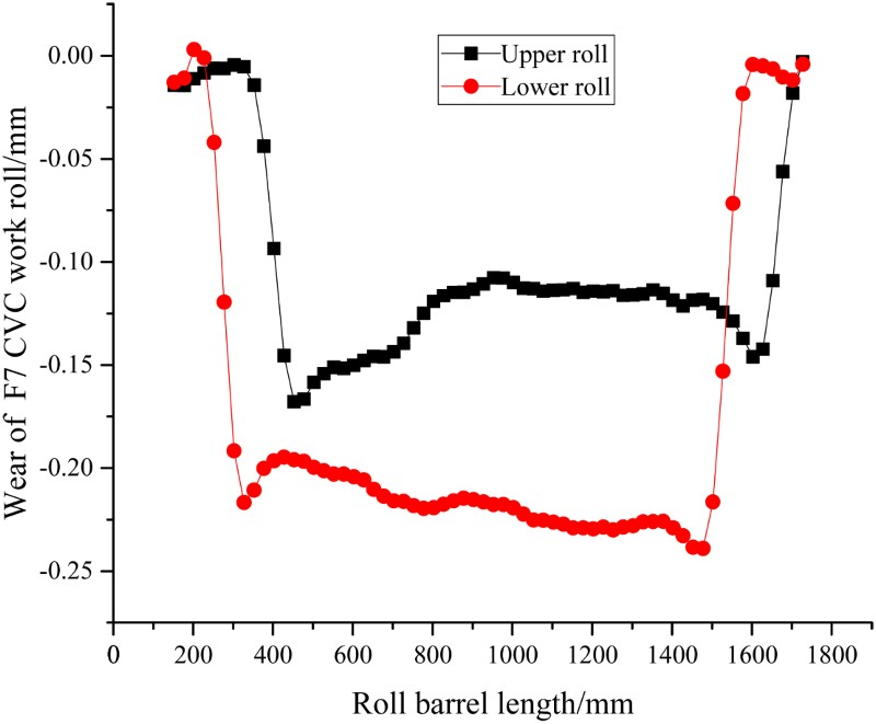
However, silicon steel has higher demands for the cross-section shape in hot rolling, which not only need to ensure the stability of the target crown but also need to reduce edge-drop in the whole hot rolling schedule. The problem of correcting both crown control and edge-drop in a CVC mill is that edge-drop compensation requires the positioning of local features of the roll close to the strip edge, whereas the CVC principle causes the effective roll camber to vary as a function of the shift position. The CVC mill is well suited to controlling one or the other parameter, but not both together. For the purpose of controlling edge-drop, the new technique for controlling the cross-section shape of the silicon steel strip must achieve roll free shifting and large stroke to improve strip edge-drop, and keep silicon steel crown and wedge stability in the whole rolling schedule at the same time.
Design of large concave roll
The novel roll technology should guarantee the silicon steel crown stable before and after roll shifting. Meanwhile, the novel roll needs to compensate the initial roll gap crown formed by the CVC rolls so that it can ensure the stability of rolling process. Based on the above demands, the large concave roll (LCR) was designed for rolling silicon steel. The form of the LCR is quadratic curve.
The upper roll curve


Formula (1) minus (2), obtaining the corresponding formation of roll gap under no load condition:


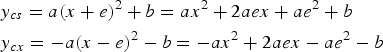


The back-up roll (BUR) is also the CVC profile paired with the WR in a steel rolling plant. Its rolling cycle is long. So the BUR curve cannot be modified arbitrarily. However, the LCR and the CVC BUR are not well paired with each other, which is easy to cause corner contact, effecting the roll body safety. So it is needed to modify the LCR edge to the taper curve. The middle position of the WR adopts quadratic curve and the edge position of the WR adopt double taper curve. Finally, the WR profile is fitted to a sextic curve. The sextic curve need to keep the centre of the roll as quadratic curve, and the WR edge corresponding to the strip edge position keep the curve sextic components as small as possible. The final formation of the sextic and quadratic WR curve is shown as the curves 1 and 2 in Fig. 3. Furthermore, the roll curve corresponding to the edge of strip can be modified to the curve 3. Large concave roll shape. Curve 1 – LCR of quadratic curve, curve 2 – LCR with centre quadratic curve and edge taper curve, curve 3 – LCR with centre quadratic curve and edge large taper curve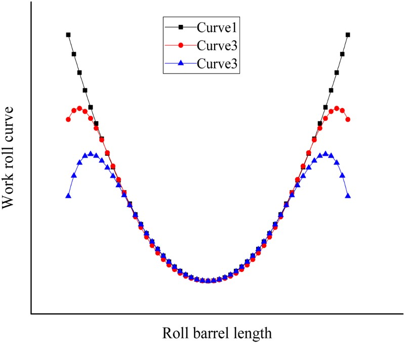
The roll gape crowns formed by the curves 1, 2 and 3 under no load condition are shown in Fig. 4. The positions of those crowns are corresponding to the strip edge. The crown of roll gape formed by curve 1 is constant, while those crowns of the roll gapes formed by the curves 2 and 3 change with the roll shifting position. Although the roll gape at the strip edge will vary with the roll shifting position, the strip crown under load condition can be compensated by adjusting roll bending force. The curve 3 is benefit for reducing the edge-drop of the hot rolled strip. Crown of roll gape at edge of strip. Curve 1 – LCR of quadratic curve, curve 2 – LCR with centre quadratic curve and edge taper curve, curve 3 – LCR with centre quadratic curve and edge large taper curve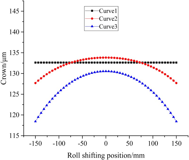
Roll shifting strategy of large concave roll
The free shifting strategy is very helpful to keep the uniform wear of the WR, which is benefit for controlling the strip cross-section shape and expanding the number of rolling kilometres. The crown regulating range in the hot continuous rolling is large because of the various grades and specifications. However, the crown of the LCR is fixed, and it can merely compensate the insufficient control ability for the strip crown by the WR bending force. Therefore, it is not available for the upstream stands. At present, the WR shifting strategy is mainly based on empirical setting, lack of theoretical basis. Shao et al. 20 established the quantitative relations between the WR wear characteristic parameters and roll shifting strategy parameters. It analyses the effect of roll shifting strategy on the WR wear feature parameters. The optimisation of roll shifting strategy is a complicated math problem. The wear evaluation function has many parameters and it is difficult to guarantee the accuracy of the results. In this paper, the different roll shifting strategies are simulated by the hot rolling calculation software developed by our research group. Besides, the conclusion of the Shao et al. 20 is also consulted. Finally, the optimum roll shifting strategy was determined.
Figure 5 shows the F7 WR shifting schemes. The upper and lower WRs symmetrically and periodically shift. According to the characteristic of the CVC roll shifting stroke ±150 mm, the initial step lengths were set to 25, 37.5, 50, 75 mm, respectively. The step attenuation factor of the initial step length 25 mm is 0.8, and the stroke attenuation factor is 0.8. The other step attenuation factors and the stroke attenuation factors of the WR shifting scheme are 0.8 and 0.9, respectively. F7 WR free shifting strategies. (1) Initial step length – 25 mm, (2) initial step length – 37.5 mm, (3) initial step length – 50 mm, (4) Initial step length – 75 mm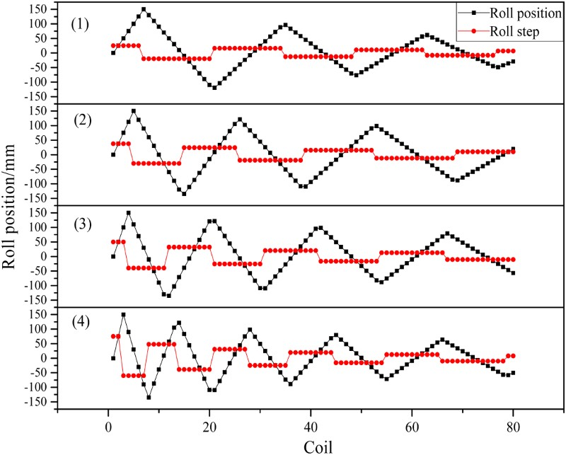
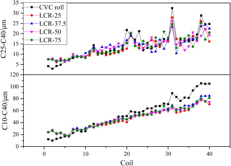
The simulation input parameters are the conventional rolling process parameters applying the original CVC profile. The LCR adopts periodically shifting strategies showed in Fig. 5. The calculated wear distribution of the F7 WR is shown in Fig. 6. The corresponding values of C25–C40 and C10–C40 of each strip in the rolling schedule are shown in Fig. 7. The legend ‘CVC roll’ in Figs. 6 and 7 indicates the F7 WRs adopt CVC profile, and the shifting strategy is the actual CVC roll shifting position in the actual rolling performance. ‘LCR-25’ represents that the F7 WRs adopt the large concave roll, and ‘25’ indicates the initial step length of roll shifting is 25 mm which is the same with the strategy in Fig. 5. The meanings of other legends are similar. As is shown in the simulation results, after the 40th strip has been rolled with the original CVC profile and the corresponding roll shifting strategy applied, the WR wear distribution of the simulation result is consistent with the measured ‘U’ shape wear of the CVC WRs shown in Fig. 1. The wear distributions of the CVC WR from 10th to 40th strip always present ‘U’ shape, and the depth of the ‘U’ shape wear increases linearly with the increase of the rolling length. The wear distributions of the LCRs adopting the shifting strategies of ‘LCR-25’ and ‘LCR-37.5’ are more uneven than the LCR adopted the shifting strategies of ‘LCR-50’ and ‘LCR-75’ when the 10th coil strip has been rolled, but the wears of the LCR adopted the different shifting strategies has little difference after the 20th coil of strip has been rolled. Compared with the CVC WR, the free shifting strategies are very beneficial to improve the wear of the WR. It makes the opening degree of the ‘U’ shape more wide and the edge of the wear profile becomes more smooth. Simulation results of F7 WR wear distribution with different roll shifting strategies-(a). (1) 10th strip is rolled, (2) 20th strip is rolled, (3) 30th strip is rolled, (4) 40th strip is rolled Simulation results of C25–C40 and C10–C40 vary with different roll shifting strategies in rolling schedule-(a)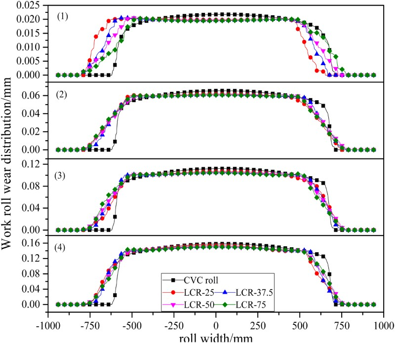
The values of C25–C40 and C10–C40 reflect the control ability of the WR profile for the strip edge-drop in the whole rolling schedule. In Fig. 7, the changes of C25–C40 and C10–C40 in a rolling schedule applying the LCR is less than those applying the CVC WR. It shows that the control ability of the LCR for edge-drop is stronger than the CVC WR, especially the control ability of C10. Owing to the simulation input parameters derived from the original CVC rolling process data, it cannot comprehensively reflect the strip crown control ability of the LCR. In the real practical rolling process, although the crown of the LCR is fixed under no load condition, it can ensure the strip target crown by adjusting the WR bending force to compensate for the control ability of the WR under load condition.
When the LCR of the F7 adopts the shifting strategy of the equal step length of 25 mm, the calculation results of C25–C40 and C10–C40 and the WR wear in the whole rolling schedule are shown in Figs. 8 and 9, respectively. In the two figures, the ‘LCR attenuation’ indicates that the shifting strategy of the F7 LCR is the periodic attenuation of the initial step length of 25 mm in Fig. 5. The ‘LCR – no attenuation’ indicates that the F7 LCR adopts the roll shifting strategy of the equal step length of 25 mm. In Fig. 8, when the 10th strip has been rolled, the wear profile of the LCR adopting the shifting strategy of the equal step length of 25 mm is more smooth than the wear profile of the LCR adopting the periodic attenuation shifting strategy of the initial step length of 25 mm. The shifting strategy of the equal step length of 25 mm makes the opening degree of the ‘U’ wear shape wide and symmetric. However, the wear profiles with different shifting strategies are similar after the 20th strip has been rolled. Simulation results of F7 WR wear distribution with different roll shifting strategies-(b). (1) 10th strip is rolled, (2) 20th strip is rolled, (3) 30th strip is rolled, (4) 40th strip is rolled Simulation results of C25–C40 and C10–C40 vary with different roll shifting strategies in rolling schedule-(b)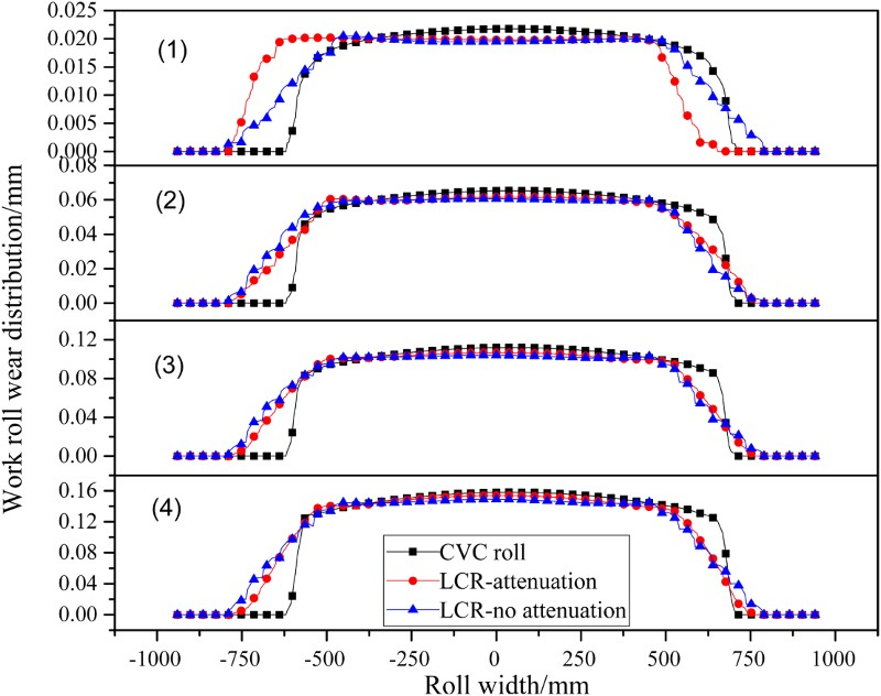
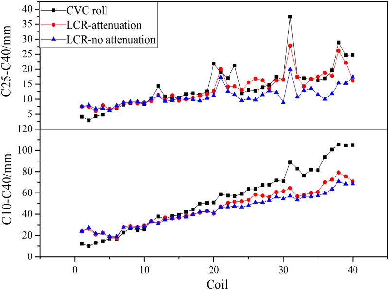
Figure 9 shows that the strip crown difference C25–C40 and C10–C40, adopting the shifting strategy of the equal step length of 25 mm, are less than those adopting the periodic attenuation shifting strategy of the initial step length of 25 mm. In addition, the effects of different step lengths (37.5, 50 and 75 mm) on the control ability of the edge-drop in the whole rolling schedule were also analysed. The results show that too small (25 mm) or too large (75 mm) step length of roll shifting is not good for controlling the strip edge-drop. Because the coil quantity of the silicon steel schedule is relatively small and the strip specifications in a schedule is from wide to narrow, the simulation results show that the effect of the roll shifting strategy of the equal step length on the strip crown and edge-drop is little. However, it had better consider the effects of attenuation factors of both the step length and stroke for the large schedule and schedule-free rolling based on the wear effect mechanism.
Hot rolling experiments of large concave roll
Based on the above analyses and conclusions, five times rolling experiments adopted the LCR with edge taper curve were carried out. The roll shifting strategy is periodic shifting of the equal step length of 25 mm. The previous three experiments were carried out on the carbon steel, and the following two experiments were carried out on the silicon steel. The third experiment totally rolled 70 coils of strip. The grades include MRTRG00101, MRTRG00301, SPHC-YH, MRTP121001, MRTHY26001, MRTLA42002, MRTLA30001. The whole rolling process was very stable. The strip crowns varying with the specifications changing in the whole rolling schedule are shown in Fig. 10. The changes of the strip crown difference and wedge in the whole schedule are shown in Figs. 11 and 12, respectively. Strip crown indexes vary with specification changing in the third experiment C25–C40 and C10–C40 vary with specification changing in the third experiment Strip wedge indexes vary with specification changing in the third experiment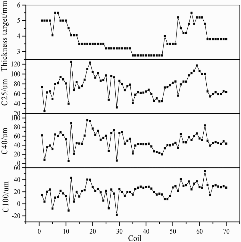
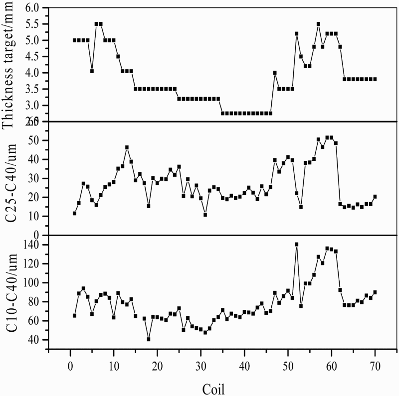
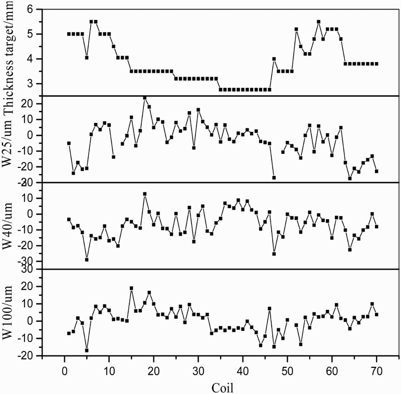
Figure 10 shows the crown of first coil of strip changes dramatically at the time of specification changing. This is due to the lack of self-learning coefficients in the control system, but the strip crown would hit the crown target as long as two or three coils of strip of the same specifications have been rolled. And the hit rate of the crown target could reach more than 95%. It indicated that the self-learning coefficients could quickly become very accurate after two coils of strip have been rolled. Owing to the reasonable concave of the WR, the roll bending force in the experiment was relatively small, basically less than 500 kN. The experiment result shows that the new strategy could increase the shape control capability to utmost extent. In Fig. 11, the values of C25–C40 and C10–C40 did not increase with the rolling schedule, they can still maintain relatively stable even in the late phase of rolling schedule. We could also conclude that the wedges of all the strips in the schedule were very small in Fig. 12. All the results showed that the LCR would not have an adverse impact on the strip wedge.
Based on three times experiment on the carbon steel, we can conclude that the LCR had no effect on the rolling stability, and the experiment was finally carried out in the silicon steel schedule. The number of the strip in the schedule was 58 coils. The strips of silicon steel, the grade W470, were rolled from the 11th coil to 42th coil, a total of 32 coils. All the strips from the coil of the 1th to the 10th and the 43th to the 58th were the carbon steel (MRTRG00101, SPHC-YH), a total of 26 coils. Roll shifting strategy was the periodic and equal step length of 25 mm. The results of the strip crown and wedge compared with those rolled by the original CVC roll are shown in Figs. 13 and 14, respectively. Figure 13 shows that the C40 and the C25 of strips were all stable in the rolling process adopting the LCR. They were smaller than those strip rolled by the original CVC roll. The hit rate of the C40 was more than 99%. The strip crowns were stable in the late of the whole rolling schedule. And the cross-section of the strips at the late stage was consistent with those in the middle segment. Comparison of C25 and C40 distribution in hot rolled silicon steel schedule Comparison of W25, W40 and W100 distribution in hot rolled silicon steel schedule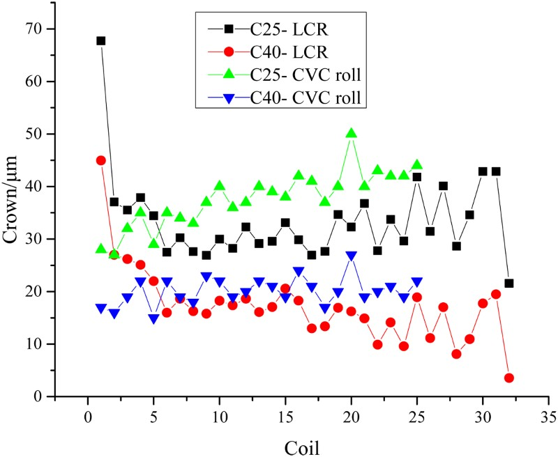
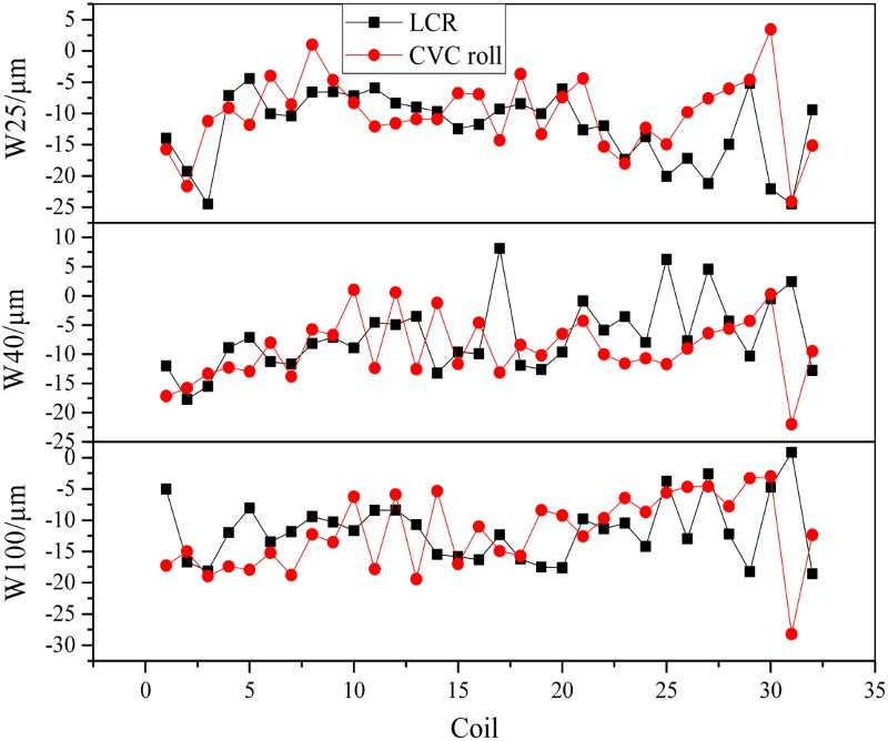
In Fig. 14, the wedge of the position of 25 mm from the strip edge (W25), the wedge of the position of 40 mm from the strip edge (W40), and the wedge of the position of 100 mm from the strip edge (W100) were mainly concentrated at the −10 µm, which were the similar with those rolled by the original CVC roll.
After the first experiment on silicon steel, another experiment of the LCR on two rolling schedule of silicon steel was carried out. The strip quantity of one rolling schedule was 81, and the other was 73. The wear profiles of the upper and lower LCRs in the three rolling schedules were compared with the wear profiles of the original CVC WRs applied to roll silicon steel in Fig. 15. The graph (1) in Fig. 15 is the profiles of the CVC WR by which more than 40 coils of strip had been rolled. The total rolling weight was 900 metric tons, and rolling length was 37 km. The graph (2) in Fig. 15 is the profiles of the LCR by which 58 coils of strip had been rolled in the first experiment. The profiles in the graphs (3) and (4) are also the LCR after rolling in the second experiment, in which 81 and 73 coils of strip had been rolled, respectively. The results show that the opening degree of the wear profiles of the LCR becomes smooth, which is consistent with the simulation results. The step length of the roll shifting in the second experiment was about 5–10 mm which was different from the equal step length of 20 mm in the first experiment. Meanwhile, the strip quantity in the second experiment was 23 and 15 more than that in the first experiment, respectively. The wear losses in the graphs (3) and (4) were less than or nearly equal to that of the CVC roll in the graph (1). However, the opening degree of the WR wear profiles was improved compared with the ‘U’ shape wear profiles of the conventional CVC rolls. The results prove that the periodic roll shifting strategy is favourable for improving the WR wear profiles, and it also indirectly indicates that the LCR is benefit to the edge-drop control in the late of rolling schedule. If the roll shifting strategy of the second experiment on silicon steel keep consistent with the strategy of the first experiment, or is further optimised, the strip quantity in a rolling schedule can be further increased on the basis of the current 45 coils when the LCR is adopted. Wear profiles of CVC roll and LCR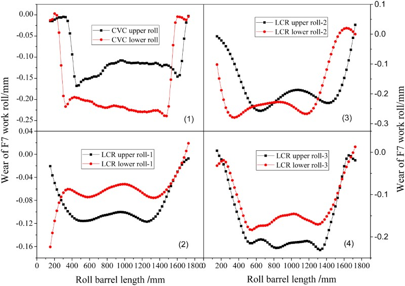
The experiments on both carbon steel and silicon steel showed that the LCR can be widely applied to the downstream stands. As a result of a wide and general product mix in the hot rolling line, the LCR with a suitable crown can be applied to different steel grades whose crown targets are similar to each other. Therefore, two or three kinds of the LCRs with different crowns are needed, which is mainly determined by the range of the strip crown target. It may increase the difficulty of the preparation of the WR. If the LCR is applied to all kinds of grades, the BUR curve is needed to modify to accommodate the LCR profile. A quadratic BUR curve is designed to accommodate the LCR. Simulation is done to analyse the influence of the quadratic BUR curve paired with the LCR on the pressure between rolls and the strip edge-drop. Figure 16 is the profiles of the novel quadratic BUR and the original CVC BUR. Profiles of CVC BUR and quadratic BUR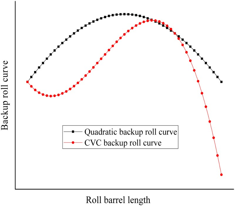
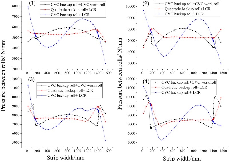
Figure 17 is the comparison of strip profiles. If the LCR is paired with the quadratic BUR, the strip rolled by them can improve the strip edge-drop compared with the strip rolled by the original CVC WR and the CVC BUR. The strips rolled by the LCR paired with the quadratic BUR are similar with those rolled by the LCR paired with original CVC BUR. It shows that the profile of BUR has little influence on the strip edge-drop, but a little influence on the central profile. However, the profile of the BUR paired with the WR has a significant impact on the pressure distribution. Figure 18 shows that the pressure between the original CVC WR and the CVC BUR is symmetrical, but becomes uneven with the increase of rolling length. The novel quadratic BUR paired with the LCR improves the pressure distribution compared with the CVC BUR paired with the LCR. The results indicate that it had better to modify the original CVC BUR to accommodate the LCR profile. Optimisation of the BUR can not only increase the stiffness of the roll gap to improve the strip profile but also make the pressure distribution between rolls uniform. Profiles of strip rolled by CVC BUR and quadratic BUR Pressure comparison of CVC BUR and quadratic BUR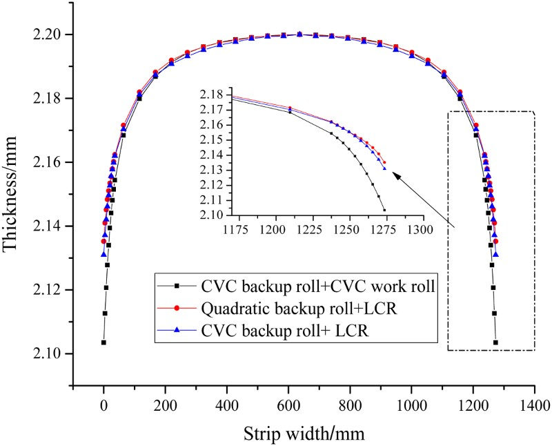
Mean value of crowns of hot rolled strip in the same specification
Transverse thickness difference of cold rolled strip of in the same specification
The crown target of the hot rolled strip, C40, is 20 µm. So the actual C40 of the strips rolled by both the LCR and the original CVC roll is approximately equal. Owing to the increase of thermal crown of the LCR, the mean value of the C40 is less than that rolled by the original CVC WR. In addition, the C25 of the strips rolled by the LCR is less than that rolled by the original CVC roll. In Table 2, the corresponding transverse thickness differences of the strips rolled by the LCR decrease 0.2–1 µm than the previous months after cold rolling. The percentage of the transverse thickness difference less than 8 µm increases by 13–28%, and about 92.6% of the transverse thickness differences were less than 10 µm. The results show that it can decrease the transverse thickness difference of the cold rolled strip by reducing the edge-drop of the hot rolled strip. The roll edge of the LCR modified to the taper curve can further reduce the hot rolled strip edge-drop.
Conclusions
Based on the above experimental data, we can draw the following conclusion: Both the upper and lower WRs are designed to the LCR with the quadratic curve, and the symmetric shifting of both the upper and lower WRs can ensure roll gap constant under no load condition. The shifting strategies, that both the step and the stroke are equal without any attenuation or not equal with attenuation, can improve the WR wear uniform. The shifting strategy of the equal step and stroke is conductive to improving the strip edge-drop in the late of the rolling schedule in case that the quantity of silicon steel in a rolling schedule does not exceed 70 coils. The LCR with the quadratic curve can be applied to roll silicon steel. Compared with the original CVC roll, the LCR can significantly reduce the C25 and C10. It can realise the free shifting under the condition of achieving the stable control of the crown target. The LCR can improve silicon steel edge-drop in the late of rolling schedule and extend rolling schedule with roll free shifting. It is benefit for the reduction of the transverse thickness difference of the silicon steel strips in the subsequent cold rolling to decrease the edge-drop of the hot rolled strip. However, there are shortcomings of the LCR. First, it is not conducive to the frequent change of strip specifications. The strip crown is not stable before and after specifications changing. The control system needs to learn a lot of new self-learning coefficients of models. Besides, the free roll shifting strategy and the original CVC shifting strategy are different, and the control system needs to be modified.
Footnotes
Acknowledgements
This research is sponsored by the Hebei Provincial Natural Science Foundation of China (Grant No. E2016203482), Hebei Provincial Science and Technology Research Foundation of China (Grant No. ZD2014034) and Youth Independent Research Program of Yanshan University (Grant No. 14LGA003).