
Abstract
COREX is the first industrialized non-blast furnace ironmaking process in the world. The melter gasifier, where final reduction of iron ore and melting of direct reduction iron take place, plays an important role in the process. In this paper, a three-dimensional mathematical model is used to simulate the combustion process of dust in the dome of a COREX gasifier. The model geometry covers oxygen spray gun, dust spray gun, top wall surface and raw gas outlet of the melter gasifier. The typical phenomena of in-gasifier aerodynamics and physicochemical behaviours relevant to the injection of dust with different granularity are simulated, in terms of flow, temperature, gas composition and coal combustion characteristics. The results show the dust particle size has a certain impact on the dust combustion. With the increase in the dust particle size, the dust burning rate and the dome temperature decreases, while the reducing gas concentration increases.
Introduction
In response to environmental protection and resource shortage issues, smelting reduction ironmaking technology has been continuously improved and developed [1]. The COREX method, as the only smelting reduction process for industrial production, has many advantages over the traditional blast furnace ironmaking process: First, low requirements on the quality of raw materials and fuels in the COREX process frees itself from the dependence of the coke that is necessary for blast furnaces, and reduces the pollution caused by coking. Then, compared with the blast furnace ironmaking process, the COREX process is flexible in operation due to its simpler device [2]. However, the COREX process still has many problems [3] that need further study.
As shown in Figure 1(a) [4], the COREX process combines the two mature processes of shaft furnace and coal gasification, and it is mainly composed of melting gasifiers, prereduction furnaces, feeding equipment and tail gas treatment. The upper part of the COREX process is the reduction shaft furnace, which bears the reduction reaction of ore. The lower part of the COREX process is the melter gasifier, which is equivalent to the bosh and hearth of the blast furnace [5]. Further reduction and slagging of sponge iron added by the shaft furnace occur in the melting gasifier, as shown in Figure 1(b); so the gasifier is the key and also a restrictive link to COREX process. Providing pre-reduced gas and heat for the upper reduction shaft furnace are the main functions of the melting gasifier, which mainly relies on the combustion of coal and dust. Schematic diagram of COREX process and smelter gasifier.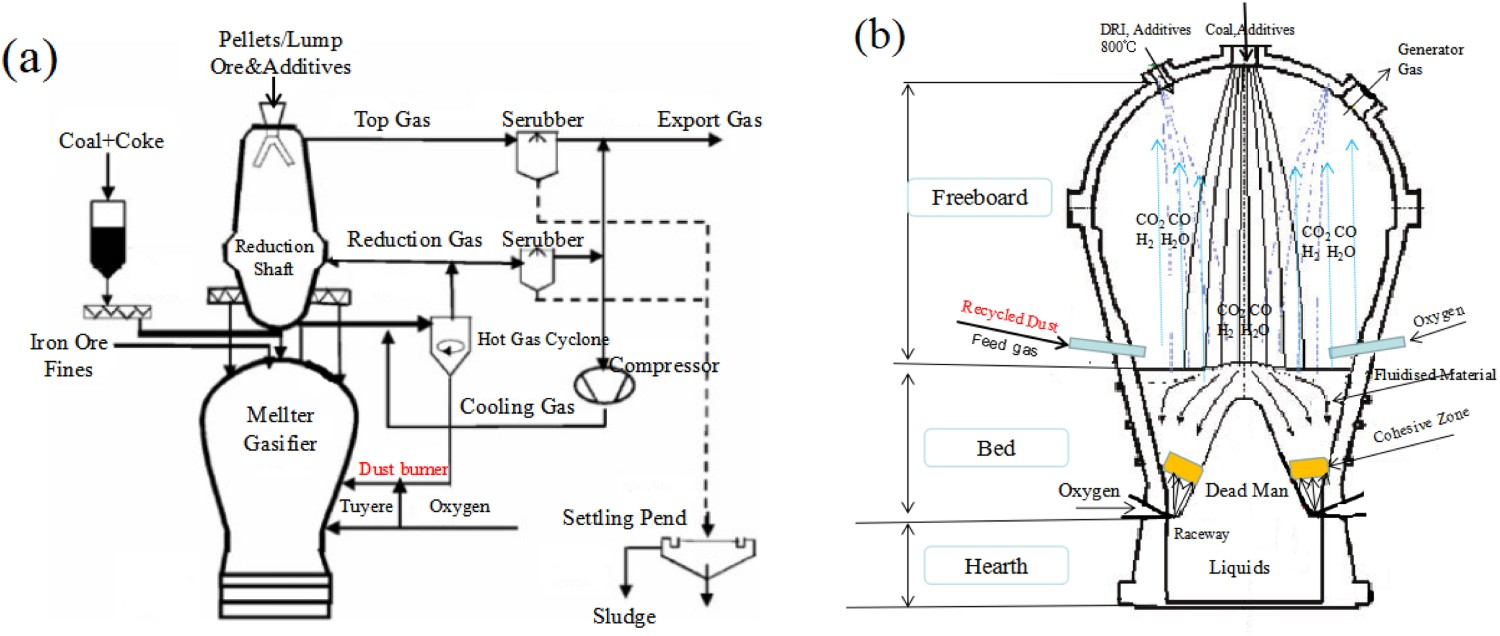
Combustion of carbon dust [6] in the oxygen burners, located in the gasifier's dome, is an important measure to balance the dust load in the dome atmosphere. The dust is separated from coal gas by dust removal equipment and re-injected into the gasifier dome through carrier gas nitrogen. Furnace temperature and gas composition will be affected due to the combustion of dust; so it is important to study the dust combustion in the gasifier's dome. The particle size of dust is complex and it contains coke and nut coke, which may have an influence on the dust combustion. The combustion process of dust in the gasifier dome cannot be detected by actual monitoring, and the combustion process of dust is very complex, including a mixture of dust and pure oxygen; the exchange of momentum, heat and mass; and the combustion of dust. Using experimental methods to understand the influence of particle size on the dust injection process not only requires a lot of manpower, material resources and financial resources, but also there are some gaps between the experimental results and the actual situation. Actually, it can use the simulation method to calculate the process of the dust combustion. However, the current numerical simulation of the COREX gasifier mainly focuses on the char combustion in the pipeline [7] and ignores the combustion of dust on the gasifier dome.
In this paper, a three-dimensional mathematical model is used to focus on the conversion of the dust and the effects of carbon dust burning on the dome gas composition. Comparisons of the combustion performance between three dust types with different particle sizes are studied under COREX conditions, in terms of flow, temperature, gas composition and coal burnout. Such a comparison will help to investigate the technical feasibility of blowback dust.
Model description
Basic equations
The commercial software Fluent 17.0 is used to predict the combustion process of dust in the melter gasifier. The turbulent flow, particle motion, dust combustion, homogeneous chemical reaction, gas radiation models and reduction model are briefly described as follows: The realizable 

Lagrange method was used to model the dust. Dust particles follow the discrete particle trajectories regardless of the interaction between the coal particles due to the weak force interactions between the coal particles. Particle movements were calculated by Newton second law, where turbulent diffusion and gas resistance are considered. The change in particle temperature is determined by three heat transfer modes: convective heat transfer, latent heat transfer related to mass transfer and radiative heat transfer. The mass, momentum and energy of particles and gas phase are completely coupled. The control equations for the gas and particle phases in the dome of the COREX gasifier have been described in detail in [9].
Combustion process
Similar to pulverized coal combustion, dust combustion is considered to be a four-stage chemical reaction: (i) preheating; (ii) Devolatilization of dust: A two-stage process is considered to describe devolatilization of dust, where volatiles (CαHβOγNδ) are released in the first stage and heavy hydrocarbons are decomposed during the second stage to form additional gases and hydrocarbons. The two-stage process is simulated using a two-competing-reactions model rather than a one-step global model used in the past [10]. (iii) Gaseous combustion: the volatile contents are released during the devolatilization process as a combination of gaseous elements of C, H, O, N, as the pseudo-volatile substance. After the combustion of pseudo-volatile substance, H2 and CO are further oxidized described by two-step homogeneous reactions that are represented by the finite rate/eddy dissipation model [11]. (iv) Char combustion: The solid char particles are formed after complete decomposition of volatile contents from the dust particles. The microporous solid char particles react with the surrounding co-flow gases following heterogeneous chemical reactions such as carbon combustion, Boudouard reaction and water gas reaction. The heterogeneous reactions proceed according to a multiple surface reaction model [12]. In this model, the rate of the particle surface species reaction depends on the diffusion of the gas phase material to the particle surface and the kinetic rate of the reaction. In order to simplify the model, other possible reactions such as iron oxides and alkali metal oxides reactions are neglected in this paper due to the small heat release/absorption heat of these reactions compared to the carbon combustion reaction, which have almost no effect to the final simulation results about the dome temperature and concentration fields. The reactions of dust and their reaction rate expressions are summarized in [13].
Geometry and operating condition
The physical model of the gasifier dome is shown in Figure 2. In the lower part of the dome, there are 4 dust burners and 6 oxygen burner distributed at the furnace wall. The oxygen burner can be simplified as a hollow cylindrical tube. Pure oxygen is blown through the burner to the dome during production. The dust burner is a ring-mounted structure, oxygen is injected in an annular area and dust is blown in the inner tube with a carrier gas. It is assumed that the bottom of the geometry is used as the upper boundary of the fluidized bed where the gas into the dome and the inlet type is set as the velocity inlet. From Figure 2, it can be seen that the diameter of the oxygen burner is 0.242 m, the diameter of dust burner is 0.364 m, and the area of oxygen annular inlet in dust burner is 0.01 m2. Dust is injected into under the same operating conditions, as shown in Table 1. The wall is uniformly set as no-sliding surface and no energy is lost during a collision between the particles with the wall. In order to investigate the effect of particle size on dust combustion, three cases with different particle diameter dust will be used and compared in terms of flow, temperature and burnout, while other conditions are fixed. They are Case 1: Dust particle size is 1–3 mm; Case 2: Dust particle size is 0.1–0.3 mm; Case 3: Dust particle size is 0.01–0.03 mm. 3D model of gasifier dome.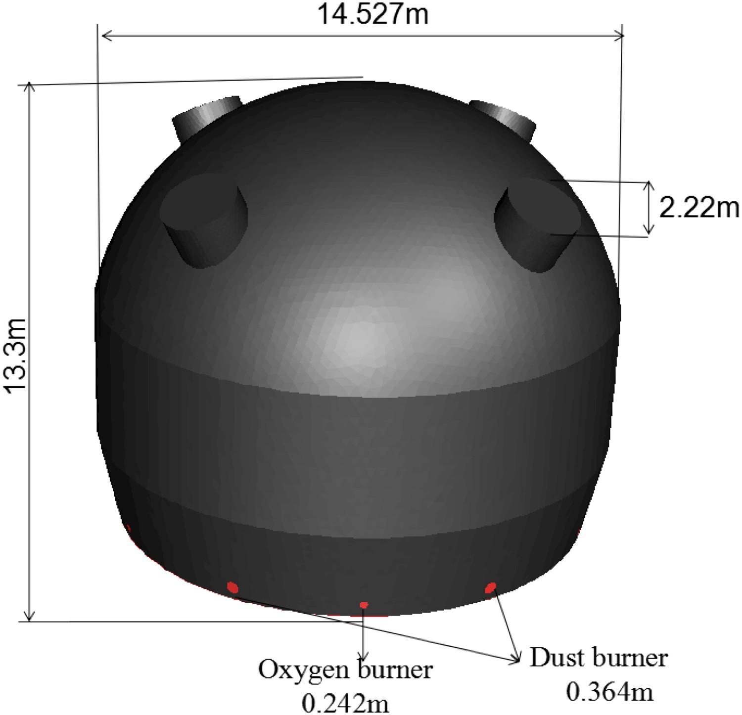
Operating conditions and boundary conditions.
Results and discussion
To probe the impact of particle size on the burning characteristics of dust with N2 as a carrier gas under COREX combustion conditions. Three ranges of particles size are considered, namely; 1–3 mm range, 0.1–0.3 mm range and 0.01–0.03 mm. Other operating conditions such as properties of the dust, input gas composition, and the dust mass flow rate are listed in Table 1.
Gas flows
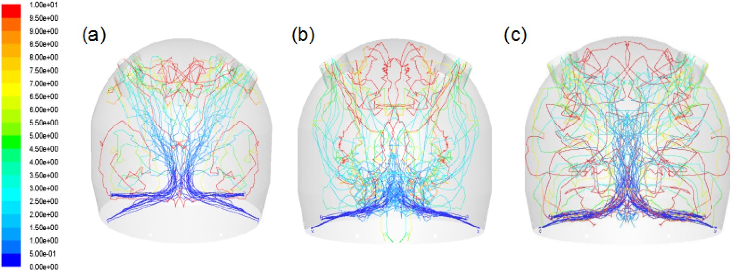
A high-velocity gas mixture of oxygen and nitrogen is injected into the gasifier through a dust burner. Figure 3 illustrates the vectors distributions within the gasifier dome for the three cases investigated in this paper. In three cases, the simulation results in an aspect of the distributions of gas vectors are very similar. Flow patterns can be separated into two parts: high-speed main gas jet and low-speed recirculation. Velocity of gas is accelerated through the burner followed by a very large gas recirculation located above the main gas jet. In the recirculation, gas velocity decreases to a low value, less than 15 m s−1 when reaching to the boundary of the gasifier. In the raceway area, relatively high-velocity jet makes more airflow move forward, not upward. In general, recirculation plays an important role in the establishment of mild combustion, and it also seems to help to establish mild combustion in the dome. The data show that there is no substantial difference in the distribution of flow paths and locations between the three recirculating vortices. It is worth noting that because of the constant jet Reynolds number, Rejet = 20000, the carrier gas flow rate is the same for the three cases. This indicates that the flow pattern in the gasifier dome is mainly determined by the rate of carrier gas injection rather than the size of dust particles. Figure 4 shows the trajectory trace of a single set of dust particles for three cases. As can be seen from Figure 4, the residence time of dust is basically similar with each other at all case operating condition, and the average time for the dust particles from entering the dome to escaping the raw gas outlets is about 4 s. This can be explained as: The flow pattern in the gasifier dome is mainly determined by the rate of carrier gas injection rather than the size of dust particles. Therefore, the larger particles or the smaller particles will obtain a similar velocity under the same gas flow conditions. Saha M et al. [12] and Liao J [14] et al have also reported the similar conclusion. Predicted velocity for cases: (a) case 1, (b) case 2 and (c) case 3. Particle trajectories coloured by particle residence time: (a) case 1, (b) case 2 and (c) case 3.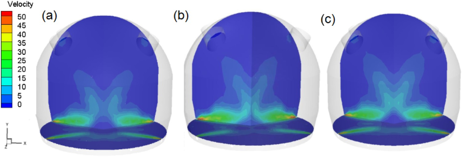
Thermochemical characteristics
Figure 5 reflects the gas composition distributions in the field of the gasifier dome, in terms of CO, CO2, H2O and H2. The distributions of CO2 and H2O profiles are largely similar but different quantitatively, CO2 and H2O as combustion products mainly in the centre of the dome, while CO and H2 are mainly concentrated on the edge of the gasifier. Approaching the gasifier centre, the concentrations of CO and H2 gradually decrease. This can be explained as follows. Oxygen content decreases dramatically after exiting the lance tip and reacts with the surrounding dust and is converted to CO2 and H2O. With the flow of gas, CO2 and H2O develop toward the centre. CO and H2 are mainly generated by the combustion and gasification of lump coal in the fluidized bed area detailed in Figure 1(b). When the gas enters the combustion interface of the dust, CO and H2 react with the oxygen in the centre zone due to the high temperature, while low temperature is not conducive to combustion behaviour, resulting in less consumption of CO and H2 in the off centre zone. Although a large amount of CO2 and H2O is generated and diffused outside the combustion zone, the concentration of CO and H2 at the dome exit is maintained at a relatively high level with the dilution of a large amount of reducing gas into the dome. Gas composition distribution within computational region for CO, CO2, H2O and H2 for three cases: (a) case 1; (b) case 2; (c) case 3.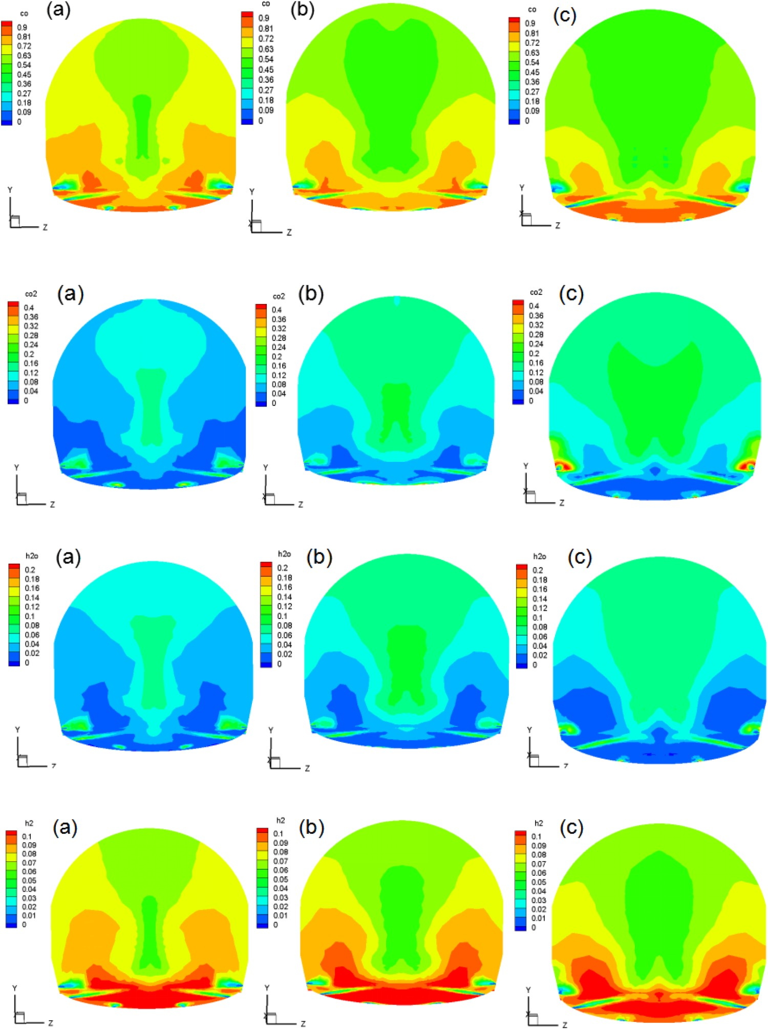
Many studies have shown that the combustion of pulverized coal or other carbonaceous materials is directly related to its particle sizes [15-17]. The smaller the particle size, the better the combustibility. As can be seen from Figure 5, the particle size has a certain influence on the gas composition of the dome. As the particle size of dust decreases, CO and H2 content decrease in the central area, and the concentrations of CO2 and H2O increase. It can be inferred that the changes in gas composition are related to the combustion of dust, the smaller particle sizes make the combustion become better due to the increasing specific surface area of the dust. Therefore, oxygen reacts with the surrounding dust whose particle size is small more violently than large particle size dust, and more CO2 and H2O are produced and diffused to the centre.
An important role of the gasifier is to provide reducing gas and heat to the shaft furnace, so the content and distribution of CO and CO2 in the gasifier are very important for the COREX process. Gases compositions of CO and CO2 along the height of the centre axis of three cases are quantified in Figure 6. From Figure 6, it can be seen that the CO2 content increases dramatically first and then decreases with increasing height of the gasifier dome. The CO content first decreases dramatically and then increases, and the two gas contents form a complementary relationship. This can be explained as: Taking case 1 as an example, within a range of 5 m of the central axis, the concentration of CO2 as a product gradually increases until reaching the maximum value 17%, while CO content decreases dramatically reacts with the surrounding oxygen and is converted to CO2. With the upward movement of gas, CO diffused from both sides to the centre, resulting in an increase in CO concentration and a decrease in CO2 concentration. Besides, the particle size has a certain influence on the gas composition in the dome. With the decrease in the particle size, the CO2 content in the gas increases and the CO content decreases, which is related to the better combustion of the dust. From Figure 6, the differences in the gases’ compositions between cases 2 and 3 are relatively small compared to the difference between cases 1 and 2, which is related to the burning of dust. It is generally accepted that the smaller the particle size of the dust, the easier it is to burn completely in the gasifier. Gas composition is affected by the combustion of dust particles: the more dust is burned, the more obvious the change in gas composition. When the dust is completely burned, the gas composition is difficult to change with the reduction of dust particles. From the above analyses, it can be inferred that the combustion of particles in calculation case 2 and case 3 is almost complete due to their smaller particles. Du K et al. [18] also reported that when the average particle size of the dust is 28.88 μm, the dust is almost completely burned at the gasifier dome. Gases compositions of three cases along the height of centre axis.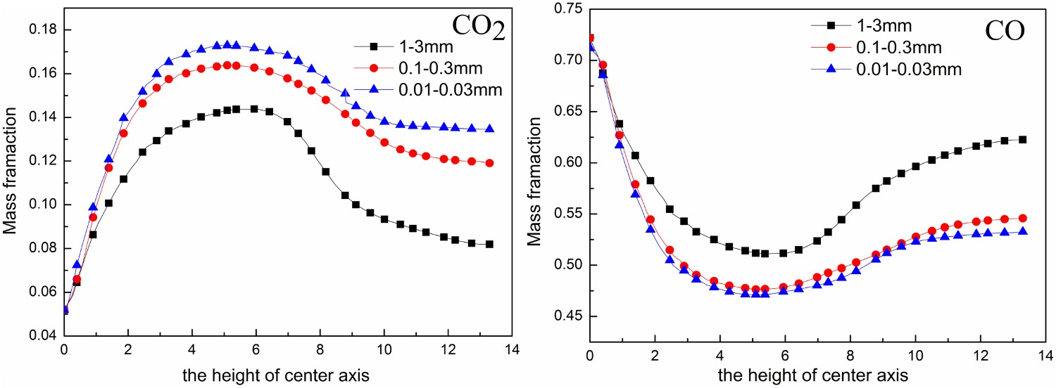
Figure 7 shows the measured temperature profile for the three cases. Their profiles are largely similar but different quantitatively. Along the main coal plume, three cases show a similar high temperature of up to 2900 K in the downstream of exiting the lance tip. The annular-like high-temperature zone termed flame front is observed and located at the surface of coal plume and in the front of the burner. On the other hand, the temperature field in this part of the smallest particle size dust case is higher than in the other two cases, by increasing the specific surface area of dust. As the temperature spreads toward the centre, the temperature in the centre of the gasifier can be ranked as case 3 > case 2 > case 1. No obvious temperature difference is found among these cases at the edge and surrounding area of the gasifier. Measured temperature distribution at the gasifier for three cases with different particles size: (a) case 1; (b) case 2; (c) case 3.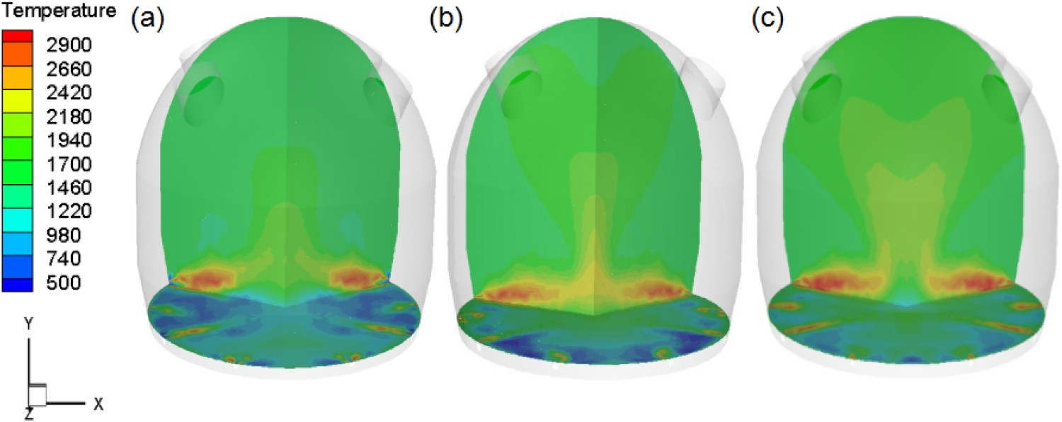
The composition of the dome gas obtained from the simulation and the production are shown in Figure 8. Case 0 represents the gas component of the raw gas exit measured in actual production. It can be seen from the Figure 8 that there is a small difference between the actual and analogue values, reflecting that the finite element volume model can simulate the actual situation of the dust combustion in the COREX gasifier dome. In addition, as the particle size of the dust decreases, the amount of CO and H2 in the raw gas decreases, while the CO2 content increases. It is obviously seen that the difference in Figure 6 of gas composition at centre height are substantial, while the difference in Figure 8 of gas composition at the gas outlets is much smaller under a different case. This can be explained as follows. Figure 6 shows the concentration of CO and CO2 at the centre height. Figure 8 shows the gas composition at the dome outlet. Compared to the edge region of the dome, more gas is produced in the centre due to the higher temperature in there. In addition, the generated gas is pushed to the centre by the air flow. Therefore, the gas composition in the central region varies greatly shown in Figure 6 under different case conditions. Although dust back blowing is an important means of adjusting the composition of the raw gas, the composition of the gas is mainly determined by the combustion and gasification of coal. The gas outlet is located at the edge of the dome and the gas composition is less affected by dust combustion; so the difference of gas composition at the gas outlets is much smaller under a different case. COREX is a complex ironmaking process that contains many physical and chemical reactions. To simplify the model, the gasification and combustion of coal and DRI are not considered during the process of their falling from the dome. Besides, the combustion of CH4 is also not considered in the calculation process. So calculated values of CO and H2 for all particle sizes are lower than measured. Gas composition of raw gas outlets.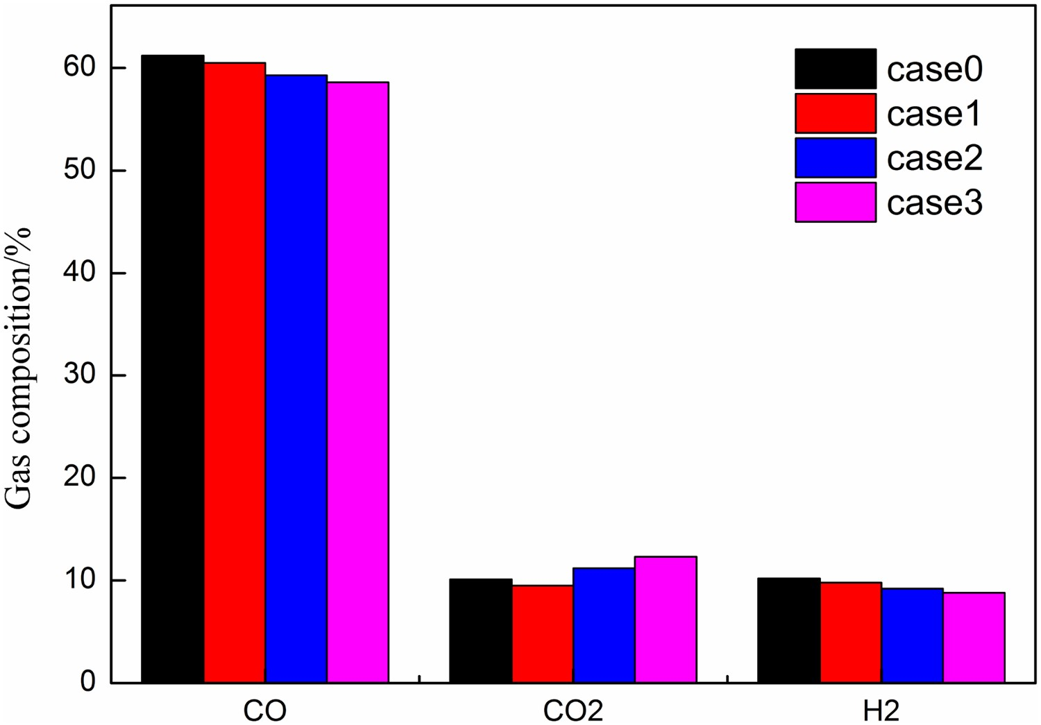
Conclusion
A three-dimensional mathematical model is used to simulate the flow and thermochemical behaviour of dust combustion in the roof of COREX gasifier. The model is then used to investigate the impact of particle size on dust combustion characteristics and illustrate other flow and thermochemical behaviours of dust in the dome. The major findings of this study are as follows: (1) The numerical models predict similar flow path-line in the furnace for both small and large particle cases. The flow pattern inside the furnace is concentrate mainly determined by the rate of carrier gas injection rather than the size of dust particles. (2) CO2 and H2O as combustion products mainly in the centre of the dome, while CO and H2 are mainly concentrated on the edge of the gasifier. With the decrease in the particle size, the CO2 content in the gas increases and the CO content decreases, which is related to the better combustion of the dust. (3) The small particle case produces higher furnace temperature than the large particle case. The high-temperature production is influenced by more specific surface area of the smaller particles case. In addition, the combustion of particles in calculation case 2 and case 3 is almost complete due to their smaller particles.
Footnotes
Disclosure statement
No potential conflict of interest was reported by the authors.